Thoughts on using old photos to scale your models:

Using old photographs to compute model size:
I was not really sure exactly where to post this topic:

This is by no means a definitive primer on how to utilize old photos when building a model. This is simply an outline of part of the process I went thru in determining measurement for a new Mack NO6 Artillery Tractor I wanted to build.

__________________

Ah, it is heavenly to find an almost prefect profile photo of the vehicle you happen to be interested in!

You then need to look for a known measurement in the photo such as the diameter of the tire rim. (not the tire but the rim - never trust the tire diameter!) You can then create a measuring scale based on that single known measurement.

Also books like Doyle’s “Standard Catalogue of US Military Vehicles” can give you basic overall vehicle dimensions. (Also available electronically.)

This is the photo I used to start my Mack NO project:

The Mack rode on 24 inch wheel rims but what you see here in the photo includes the lip around the circumference of the rim so in using this value you have to subtract approximately 3 inches from what you see here to get your scaling measurement of 24 inches. - If you forget to subtract that 3 inches your scale will end up being about 12% too large and your model will then come out 12% too small.*

3 Likes

Sample Page:

Taken from David Doyle’s “Standard Catalog of US Military Vehicles”
with basic size specifications highlighted in red.
(This catalog is also available in electronic form.)

3 Likes

Artists (and model builders) often work with proportions as much or more than with actual measurements.

Example: you might find that the hood (bonnet) of a vehicle and the cab are the exact same
length = 1 : 1 proportion, and that the loadbox is 3 times as long as the cab. So = 1 : 3 proportion relative to the hood length.

Once you discover a known measurement you will then use these proportions to calculate the actual measurement values of other items in the photo…

  • The sometimes silly image of an artist holding up his thumb at full arm’s length towards his subject is his way to actually measure his subject and determine proportions using the length of his thumbnail as a unit of measure.

  • Example: At a certain distance and angle, with his arm fully outstretched, the subject’s pupils are two thumb nails apart, her nose maybe three thumb nails long, and her temples (forehead) are five thumbnails wide. So he must then make these same proportions appear on his canvas when drawing a portrait of that particular subject.
    2 : 3 : 5.

2 Likes

Even perspective photos such as this can still be of help to you in calculating proportions and measurements:

MACKy

In this photo I have projected (in perspective) the 24 inch wheel rim measurement along the length of the vehicle - as shown by the blue lines.
Any VERTICAL measurement you wish to take along the length of the vehicle (represented by the red lines,) can use the bracketed length as being 24 inches, (along that one vertical red line ONLY.)

A low cost set of Draftsmen’s Dividers is a very good tool for measuring and transferring measurements from a photo. I will sometimes (very carefully) even use these Dividers on my computer screen to compare features.

(Even using this “system” - and I use that term loosely - it is sometimes only going to get you within one or two inches of the actual measurements. Which is why studying the visual proportions of the vehicle, just as an artist would study the face of his subject, will be more helpful to you than finding an exact number.)

2 Likes

I made the comment earlier to only trust the tire metal RIM size and to never trust the tire (rubber) diameter in a photo:

A good example I found of this was that the early Macks rode on the same rubber tire as that used by the Dragon Wagon Tractor. HOWEVER; the Mack used a narrower metal rim than the DW which pinched the tire bead and caused the same tire to stand TALLER on the Mack than on the DW - BIG DIFFERENCE!

1 Like

Since I was using the Mack NO6 above as my example, I show this model image only to represent the fruits of my “process”:

This photo also illustrates another point made elsewhere in this article:
In this image of the model I have already narrowed the rims on the front tires but as yet not narrowed the rims on the back. Can you see that even on the model those Tamiya DW tires stand taller on the front than they do on the back? * The entire vehicle is standing just slightly taller in the front than in the back and the chassis is actually slanting ever so slightly uphill towards the front axle.


Narrower wheel rims on the right but exact same tire.

  • Of course this difference would never happen on your model if you were using a solidly molded rubber tire. In this case the Tamiya tires just happen to be hollow and therefore react just as the real tire would.
2 Likes

I invite all others to add their thoughts and experiences to this topic thread.

Something that just came up in another thread. The fellow is building the newly available German PAK40 kit and said he thought the barrel was too short. (and it IS too short!)

Here is one way to use an old photo to possibly determine the answer:


Lowell, Indiana, Buckley Homestead - Mike Koenig Photo


Patton Museum, Ft. Knox 2009 - Mike Koenig Photo


I suggest taking the diameter of the wheel as a measuring unit. (The blue/green line) Then determine how many wheel diameters the barrel is long, in front of the shield, and see how that compares to your model.

By my calculations the barrel length in front of the shield is 272.6 percent longer than the diameter of the wheel. (give or take 3%)


p.s. Do make sure your model gun is fully forward “in battery” ready to fire before taking these measurements.

p.p.s. I spoke earlier of never trusting the diameter of a RUBBER air filled tire. These tires on the gun are solid hard rubber, vulcanized to the metal rim in a very standardized factory process. So these type solid tires you CAN trust for determining relative measurements.

FWIW, for years I’ve used the tabulated wheel-size data usually listed in the back appendices of books, like Spielberger’s series on German vehicles or Hunnicutt’s books on US AFVs, to scale the drawings. It seems that the drawings were usually sized to fit the available page space and are often inconsistently scaled even from one page or drawing to the next. However, these tomes almost always have tabulated data on the vehicles which almost always lists the wheel / tire diameters or vehicle overall lengths, widths or heights.

More contemporary references seem to be fairly consistent with their drawings and scale sizes (Kageroo, or MMP, etc.), but many of the older references don’t list any scales requiring the drawings to be scaled to use them.

The same tabulated data can be used to scale photos allowing for perspectives.

Here’s an example (from a build blog here on Armorama several years ago) of taking dimensional and geometry data from both photos and (scaled) drawings to solve the mystery of the late StuG IV “swinging schurtzen” scratch-built for a DML model:


Schurt-C-Radius-Diff-04b

2 Likes

I have yet to find a book with tabulated wheel sizes listed but I will take your word for it.

However in the case of your Stug I would work on the assumption that the road wheel diameter of the model is correct. I would then take one half of the road wheel diameter as seen in the drawing and use that as a basic unit of measure to determine the other measurements within the drawing.

Example: Overall vehicle length is X number of half road wheels long.

Now take the half diameter of your model road wheel and use that to measure the overall length of your model vehicle (or any other measurement you require.) Now if the measurement as seen in the drawing matches the measurement (in half road wheel diameters) of your model then you know that at least the dimensions of the drawing AND the dimensions of your model are a match.

OK then. Typically there’s one or more things/elements in a photo (better still a number of photos) of the subject that provide a reasonable gauge of size, which can then be used to estimate the measurement sought. I had that problem scratch-building the Anthropoid trailer-tram;

I couldn’t find any original plans or other tech information, so all I had was the drawing above which didn’t actually show the correct trailer OR driver-tram versions, but close enough. And a bunch of period & contemporary photos, none of which gave me a perfect side-on or end-on profile. But I did have the MiniArt driver-tram kit, so I simply compared/converted measurements from it to the trailer (using the drawing as the template) & used photos to test my eye/gut as to whether it looked “right” or not.

My philosophy about Accuracy goes like this: I’ve done the very best I can with information to hand. If there is an ultra-nerd out there who has all the original engineering plans, from the photos I publish they’re very unlikely to be able to detect with any certainty that I may be a scale-inch out here or there. But even if they think they can, frankly my dear I don’t give a flying etc.

Ideally I’d have preferred to ask my Czech correspondent to measure everything, but I was too lucky already that she was prepared to go to the Prague Transport museum to take detailed photos for me, gratis bless her…

Result:

:tumbler_glass:

2 Likes

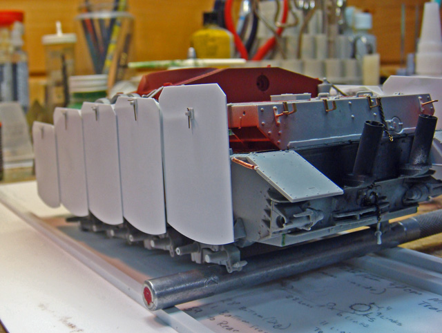
For the StuG, I assumed that the basic DML kit was either correct or at least proportionally accurate. I used used key points on the hull and suspension, taken from the photos, to identify the corresponding key points on the geometry of the swinging Schurtzen frame and parts. I then took measurements from those points on the kit to dimension the frame and parts for the build.

In this case, the kit, itself, provided the “scaled measurements” for the scratch built parts.

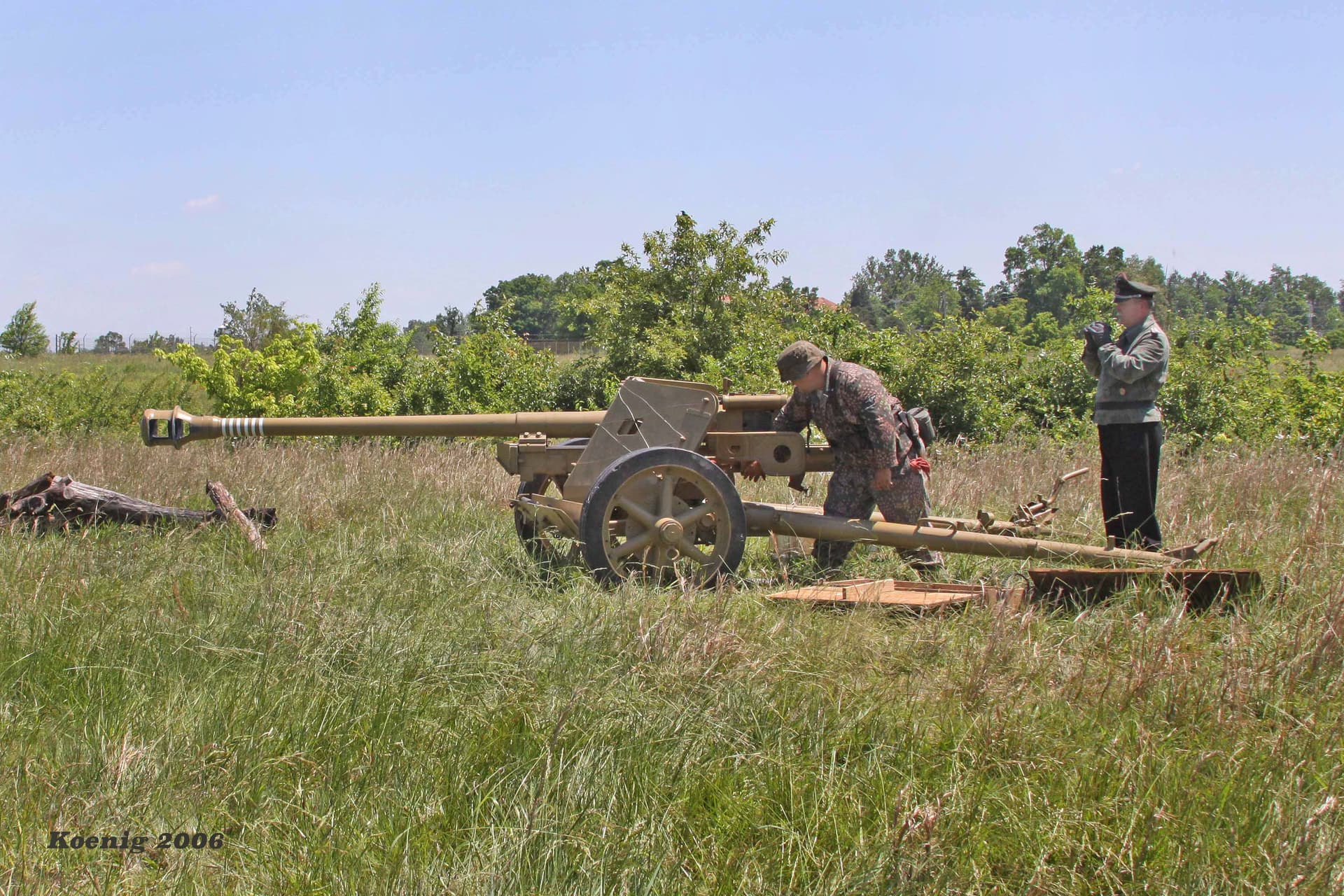
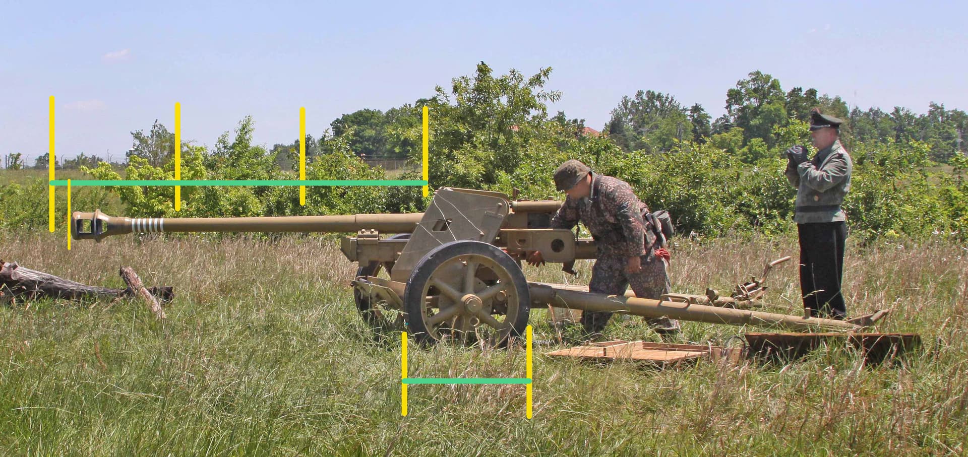
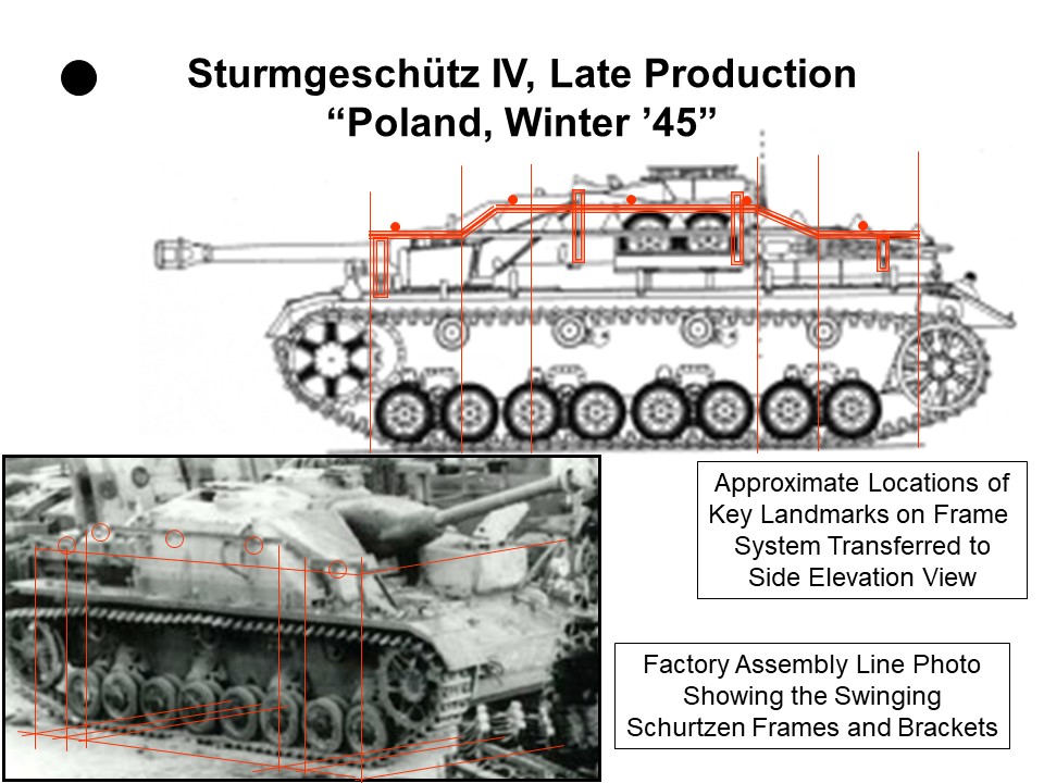
The factory photo of the StuG shows how on even an oblique shot, key points can be transferred from the photo and matched to points that can be identified on the kit. The actual measurements can then be taken from the kit to dimension the new parts.

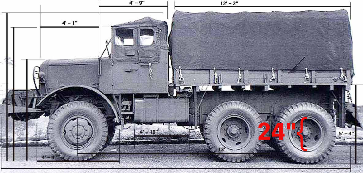
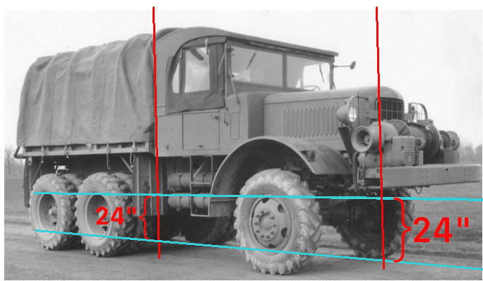
A point to note is that on the side, because the Schurtzen frame overhangs the fenders and suspension, the key points on the frame are taken from vertical lines that are drawn down to the ground level. These points are then taken back inboard along the ground to the corresponding key points on the suspension that the measurements will be taken from.

(Note that the lines on the ground that trace back to the suspension are drawn longer than needed in this example. The point at which they first touch the suspension components - either the track or the wheels - is really all that’s important. Since this was originally done just for my own use, I didn’t worry about having to explain this later.)

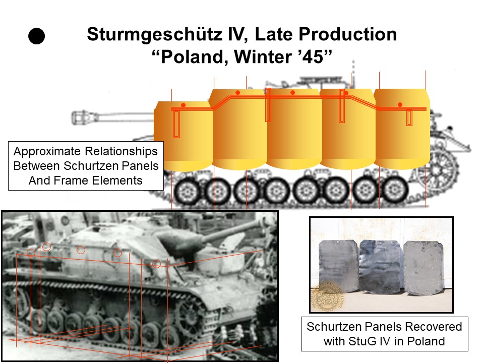
As long as the lines are kept parallel to the lines of perspective on the vehicle in the photo, their intersection points will match (at least precisely enough for the purpose) the corresponding points on the model. Taking the measurements from those points on the model is then a simple matter.

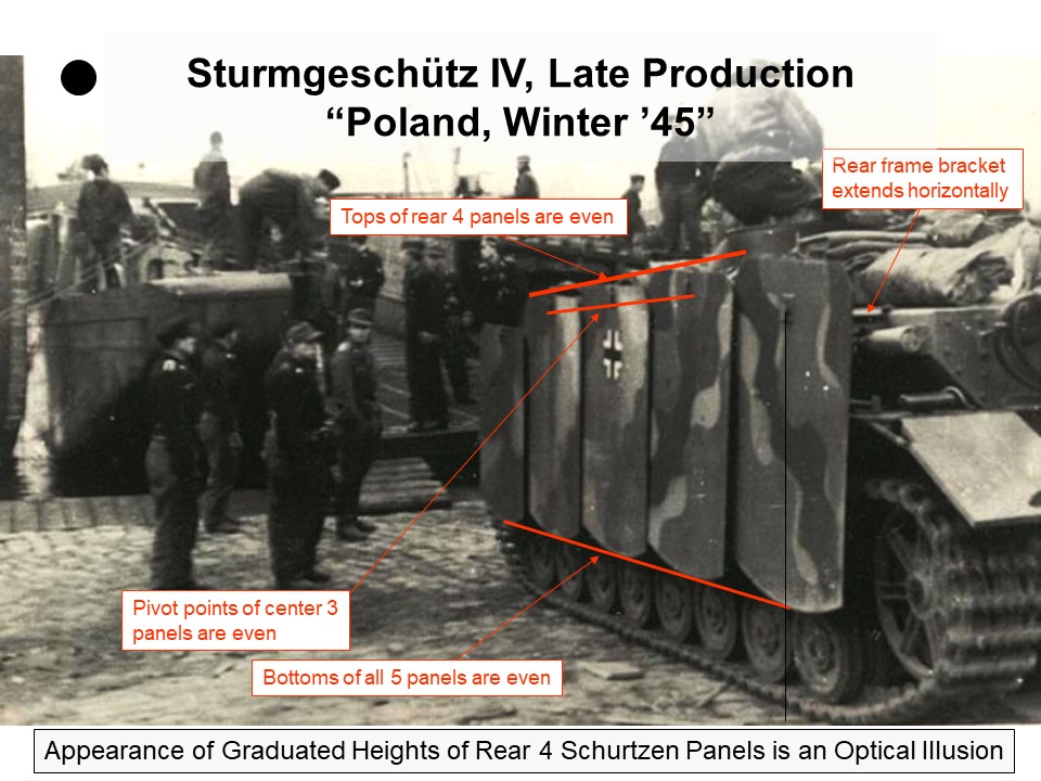
The challenge for this bit of scratch building (the swinging Schurtzen on the StuG IV) was that the only really useful references were wartime photos, all taken from various distances and perspectives. The dimensions of the actual vehicle were never in question. What was necessary here was to “reverse engineer” the design of the Schurtzen frame and parts and then dimension them accurately enough to build in 1/35 scale. There were several published sets of scaled drawings or renderings of the “swingers” which proved completely inaccurate. For many years, it was assumed that the Schurtzen plates were graduated in height - shorter in the front, taller in the rear. (Actually, only the front most panels are shorter to allow the driver to see over them with his head out of his hatch. All of the others are the same height.) This was based on a misunderstanding of the photo of the StuG being loaded on the barge. However, once you draw some lines on the photo and take into account the effects of perspective and the vanishing point, it becomes clear that all of these previously published drawings and renderings were very wrong.

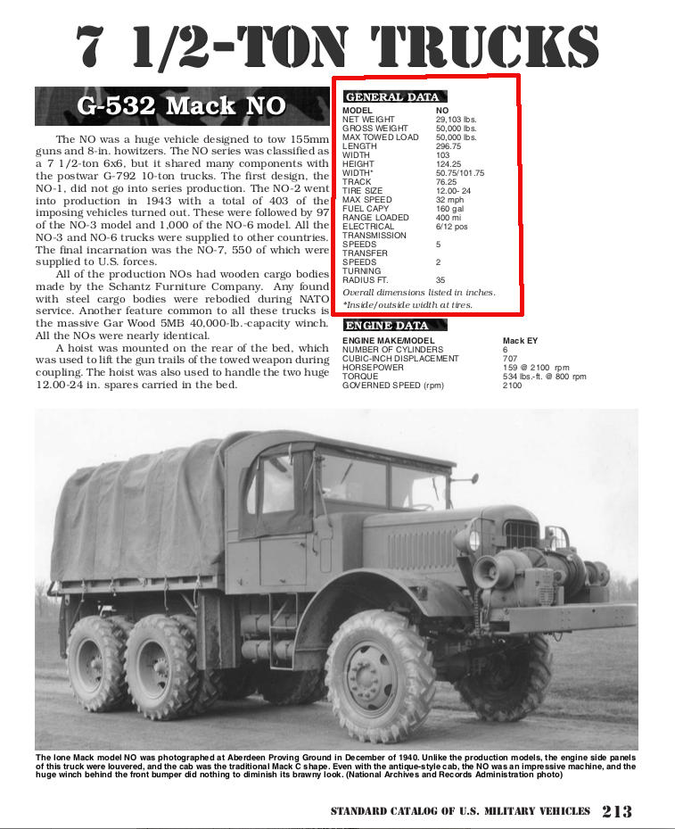
Regards to tabulated wheel sizes, all of the Spielberger books contain appendices for the vehicles covered in them in which the road wheel sizes are listed. The same is true for most of the US AFVs that are covered in the Hunnicutt books. The appendices list the road wheel sizes.

1 Like

I just used the idea of verifying the overall length of the vehicle by measuring it in multiples of the wheel diameter as an example of how one might determine other needed measurements. Much like I did with the PAK40 barrel measurements seen above.