Trumpeter 01535 M1A1/A2 5in1 "Crater Magnet"

Hey, hey. A few days ago, I started work on a Trumpeter M1A1/A2 Abrams 5in1 (Kit 01535). My builds usually stall but I decided to journal this one because input from members may help me avoid some mistakes. Please note that I am a mediocre model builder and this will be a mediocre effort. There are better builds of this specific model in these forums.

The model comes with 5 decal options. I have decided to build the M1A1HA with a Track Width Mine Plow (TWMP) and wading stacks installed called “Crater Magnet”. A quick internet search turned up one photo of a vehicle that may be “Crater Magnet”. Note that this specific tank has a round ring fitted to the drive sprocket.

This will be my first M1 in 1/35 scale and I know very little about the vehicle. The base model has many known issues. I am primarily relying on two sources to make corrections.

Comparison of M1A1/M1A2 Abrams kits

Missing Lynx Tweaks List for M1, M1A1, M1A2 Abrams Main Battle Tank

The base model has three major problems so I decided to deal with those first.

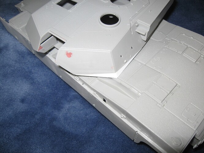
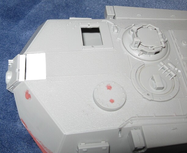
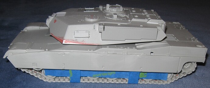
Major Problem 1 is the turret. The turret has many shape issues but the left front face is the worst. Fixing this problem results in a turret that cannot turn through 360 degrees because the hull topography is also borked. I will fix the turret face and leave the turret pointing forward. This is my progress so far…

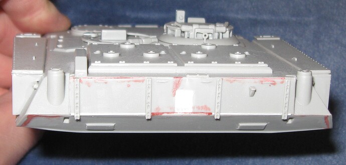
Fit of the storage boxes is also kinda wonky. Based on what I see in pictures, I tried to make the lids parallel to, but slightly higher than, the turret roof. The clips that attach the bins to the turret sides are kinda borked. I did not find a good picture of those.

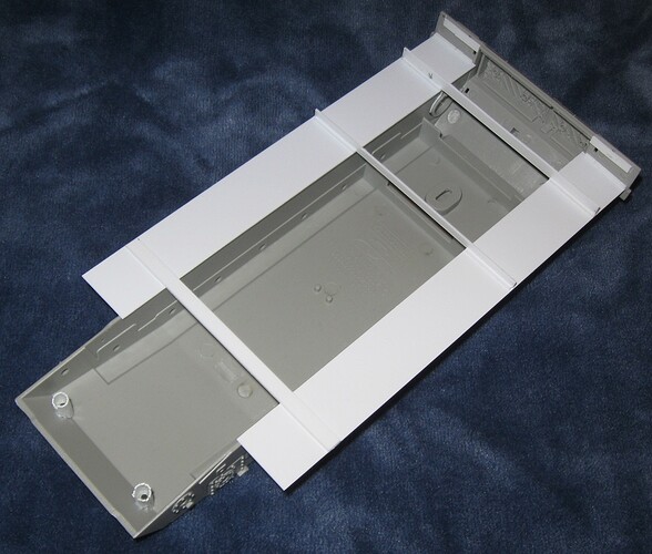
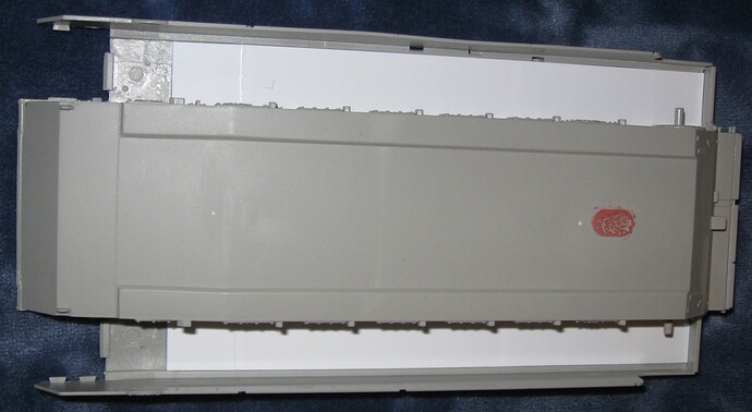
Major Problem 2 is the sponson floors–there are none. I have a plan.

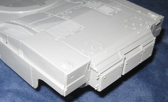
Related to Major Problem 2 is how the upper and lower hulls fit together. After a few hours of work, I have them lined up fairly well but the back rear corners need more work.

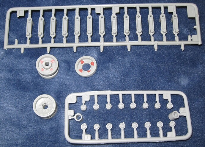
Major Problem 3 is how the road wheels attach to the swing arms. I also have a plan to fix this. The backs of the road wheels all have 4 horrible ejector pin holes that need filling. The backs of the swing arms are hollow and also need some work. This is complicated by pins on the hull that lock the swing arms to the correct angle.

That is my progress so far and represents many hours of work. Unless your time is worthless or you enjoy self flagellation, start with a better model.

As best I can tell, “Crater Magnet” is a M1A1HA used during Operation Iraqi Freedom by the United States Marines. If you know differently, please let me know.

If a correction is covered by the two sources listed above, I am already on it. If there is some glaring issues not listed in those documents, please let me know. I will probably not bother with itty bitty stuff.

12 Likes

Great job on the turret shape. The other must-fix issue is the too-short mantlet - see Part 3 of Vodnik’s article and how Trumpeter compares with Dragon and (newer) Tamiya which are correct. I can’t remember if it’s in the ML Tweaks List.

3 Likes

Thanks! I have a fix for the top of the mantlet all planned out using the Tamiya version as the template. If I can make straight cuts, it should be fairly easy.

I also found a nice walk around to help with some of the small stuff.

2 Likes

This is what I came up with for the sponson floors. Cross braces keep the new pieces perpendicular to the hull side walls.

The outer edge of each floor butts up against the inner edge of the corresponding skirt. Each floor starts at a natural rise located on the underside of the hull. These points meet one another, allowing for a strong connection. The best thing about this design is that it should make painting very easy.

There are a bunch of ejector pin holes in the back plate, forward of the sponson floors, and under the front track guards. The next step is to fill or plate over all these blemishes.

6 Likes

Looking good. I like the re-shaped turret front. In my opinion, the sponson floors aren’t really needed as you can’t see that area once the skirts and tracks are on. The only place you may see is the rear area above the sprockets if you leave the rear skirt part off. Likewise, I leave the whole top run of tracks off since they can’t be seen either.

4 Likes

Work is going slowly but things are moving along.

This is my solution to the gun mantlet problem. I cut back the opening, built one shelf high and one shelf low, then fit the mantlet to the shelves. A new top piece will drop into the hole.

I also smoothed out the new turret corner.

The back of the turret does not fit very well so I used a shim and some putty. I misunderstood Reference 1 and shaved off the mounting boss for the crosswind sensor. When I looked at pictures to see where it goes, I realized the mounting boss was in the correct place. Only the sensor mast needs to slide to the left. Oops.

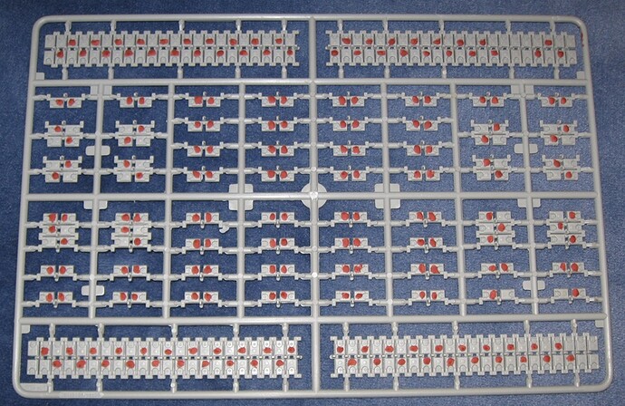
According to Reference 1, ejector pin marks on the tracks are high. Nope. Some are high and some are low. I took this picture because it shows just how many holes need filling. Some track pads on the reverse side also need filling. I know this may look like a lot of work but with a good putty, it goes quickly.

3 Likes

Link and length tracks are now mounted. Instructions for this step do NOT call out the correct pieces. However, the provided picture, while confusing, is correct. Following the picture, it is possible to assemble the tracks in the correct sequence and mount each run, in entirety, all at once.

The tracks do not appear to have a direction. However, when mounting the tracks as described above, it is necessary to wrap them around the suspension exactly as shown in the picture so direction does matter.

The provided picture shows the top track run sagging slightly at the idler and drive sprocket. I do not know if a real M1 tanks has this sag but it was added exactly as directed. This was accomplished using a long, folded pieces of paper towel. Without this slight sag, the track will be slightly too long and probably float over the return rollers. Only time will tell if my decision was the correct one.

Fit of all road wheel swing arms is way too tight at the hull and too loose at the road wheel. Enlarging the hole in the side of the hull for each swing arm is NOT the way to fix this. Instead, scrape away some plastic from the peg that slides into the hull, working all the way around the peg. Work slowly and test fit.

The backs of the road wheel swing arms are hollow. I added some card stock to strengthen them. I also added a round punch to the back of each arm, covering a hole.

The backs of the idler wheel arms are also hollow. I found it necessary to slightly shave down each mounting boss these arms attach to.

Once the idler wheel and road wheel swing arms are in place, everything is a little wonky. That is the way of this entire model. This is not a high precision tooling effort but it dates from 2002 and the finished product (with some corrections) looks decent.

With the upper hull mounted, the upper run of tracks disappears, exactly as noted by Gino a few posts up.

The upper hull and side skirts hide some additional issues. First, as per reference one, the face of each return roller is wrong. It does not matter because they are completely hidden behind the skirt armor.

The model includes one arm that extends from the lower hull face to the skirt, preventing the skirt from pinching inward and striking the running gear. A real M1 has three such arms, per side, so two are missing. A mud scraper is also missing from each side of the hull. The skirts hide these omissions.

I decided to repair the rear corners of the lower hull after hull assembly is complete. In my opinion, this is an important repair because it is very visible.

The drive sprockets have cutouts for mud relief holes but the method used to replicate the holes leaves 4 large channels in the front piece of each sprocket. I filled these channels with some card stock. the sprockets look better with this small adjustment.

The fit of the sprockets to the corresponding hull mounting pegs is way too tight. To prevent a future problem when mounting all the painted parts, I drilled out the hole on the back of each sprocket. Now they are too lose. I suspect this model was mastered using metric measurements. My drill bits are imperial.

For now, I left off the circular ring that attaches to the outer face of each drive sprocket.

2 Likes

You can have track sag and also no track, crew choice on how much work they want to do.

2 Likes

Got it. Thanks. That makes sense. Track tension varies a lot by tank model and specific vehicle.

Do M1A1/A2 tanks have any form of automatic track tension system. There is a cylinder attached to each idler wheel arm. This model does not include that mechanism but it appears in pictures.

1 Like

Yes/No, it’s the lowest ranking member of tank crew who provides the automatic muscle to keep the tension.

The real answer is no, the last I knew. Not sure the newer versions are that fancy.

3 Likes

That is a great start.