Would you happen to know the title, author, ISBN, etc. of these? ![]()
Also, for those wondering how these things steered:

Would you happen to know the title, author, ISBN, etc. of these? ![]()
Also, for those wondering how these things steered:
Thats for Vol 1 — info from online but its out of print now … all 3 are I think.
Publisher : Nigel Watson
Print length : 352 pages
ISBN-10 : 0955600901
ISBN-13 : 978-095560090

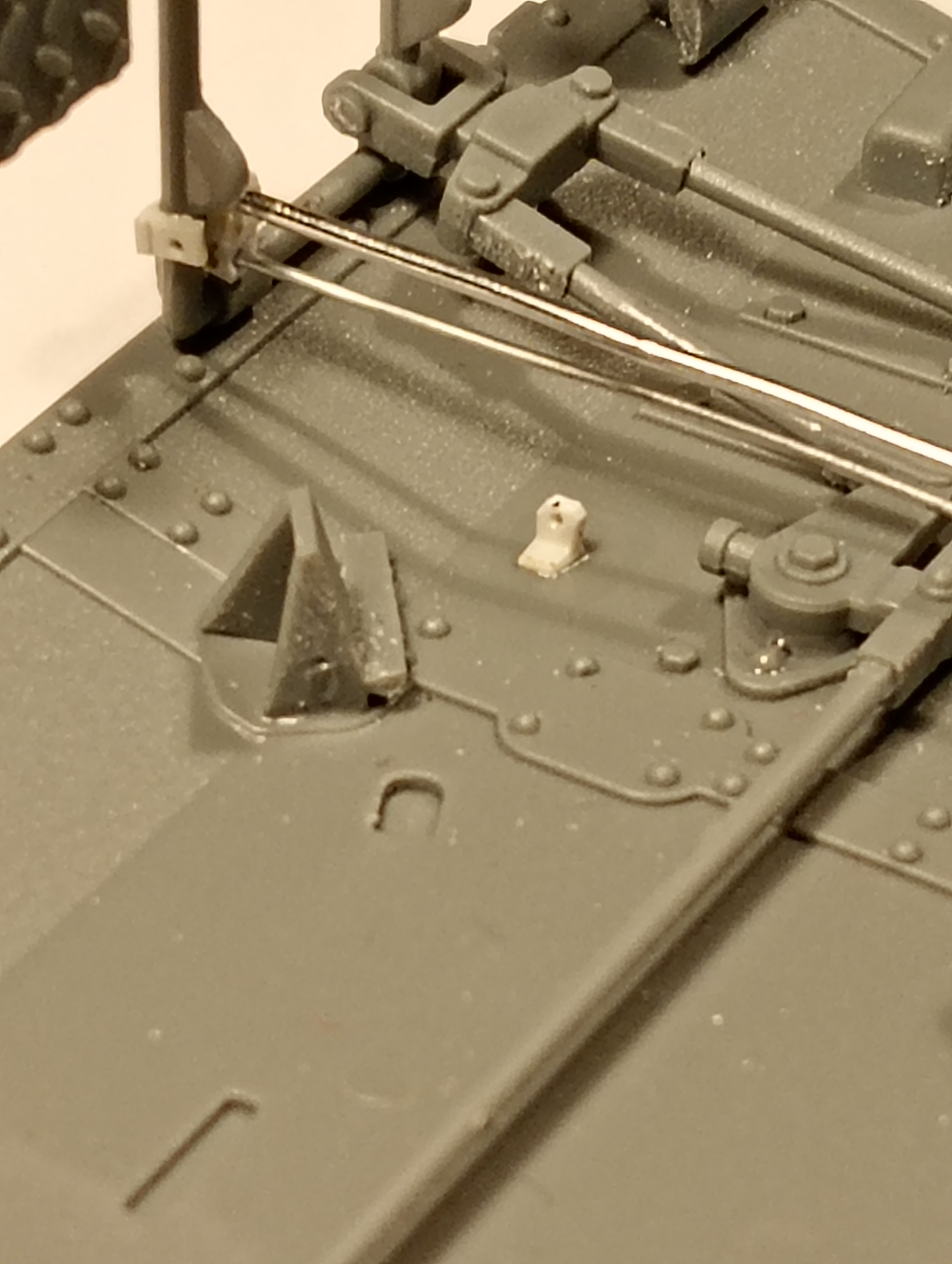
Before I attach the hull sides, I need to do a little start on the additional detailing I want to put in it … namely some cabling running along the floor and a return spring for the pedals at the front. Belly plate as it is now ….
There will also be additional cables being fitted up into the instrument panel running back towards the engine area.
The area where the drill tip is on the pedal frame will be where the 2 cables and the return spring will go … no detail included on the kit part, so will be adding that as well using drilled out and squared off plastic rod.
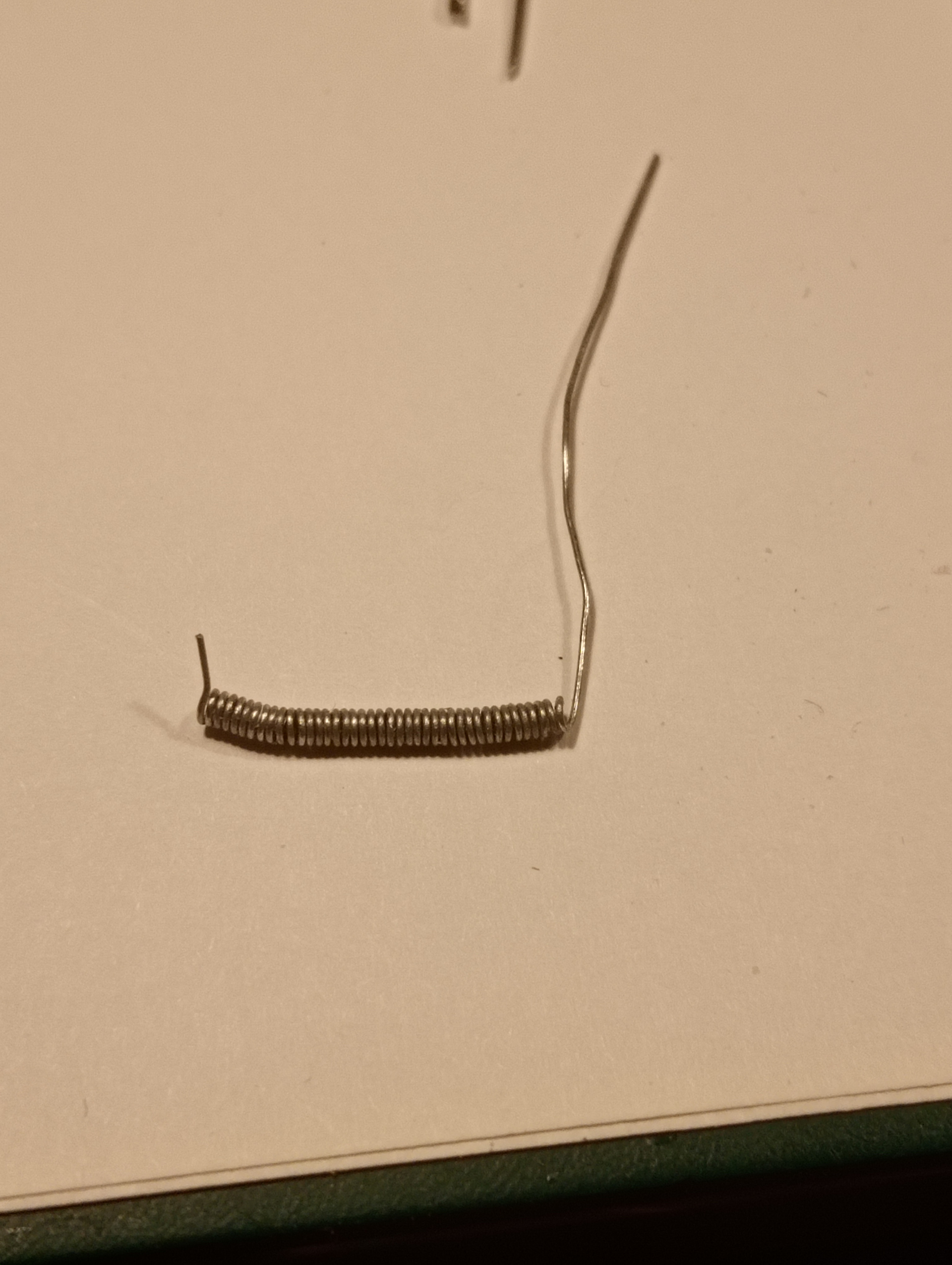
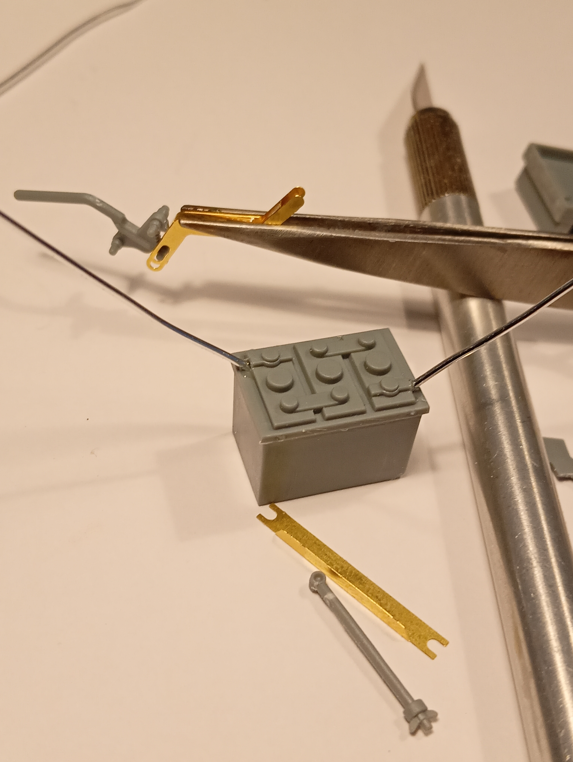
And this 0.4mm wire will become ….
Will start getting it together a bit later ![]()
Great attention to the little details. At first I thought that this was for the throttle linkage but you caught something I missed. There is a few things Gecko missed or omitted due to the fact theyre obscured by the structure once assembled. I’m sure you have worked out that the throttle rod runs back inside the same metal cover the clutch rod does. The ref pics I had showed the throttle pedal itself on a raised plate too. Trouble is you never know what is original or a period modification of later modification sometimes.
Following with added interest.
Keith
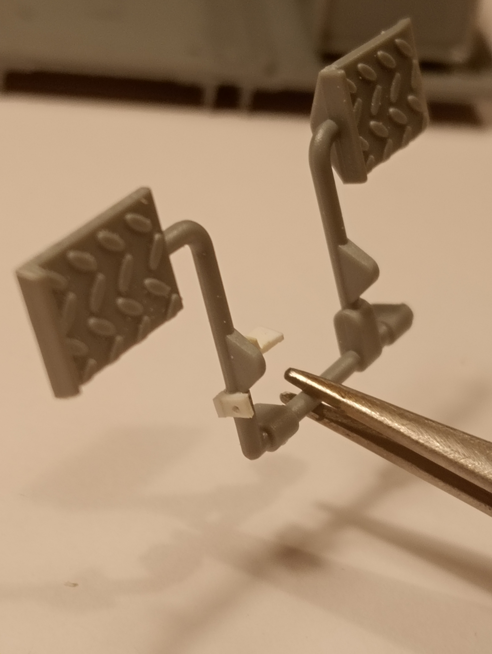
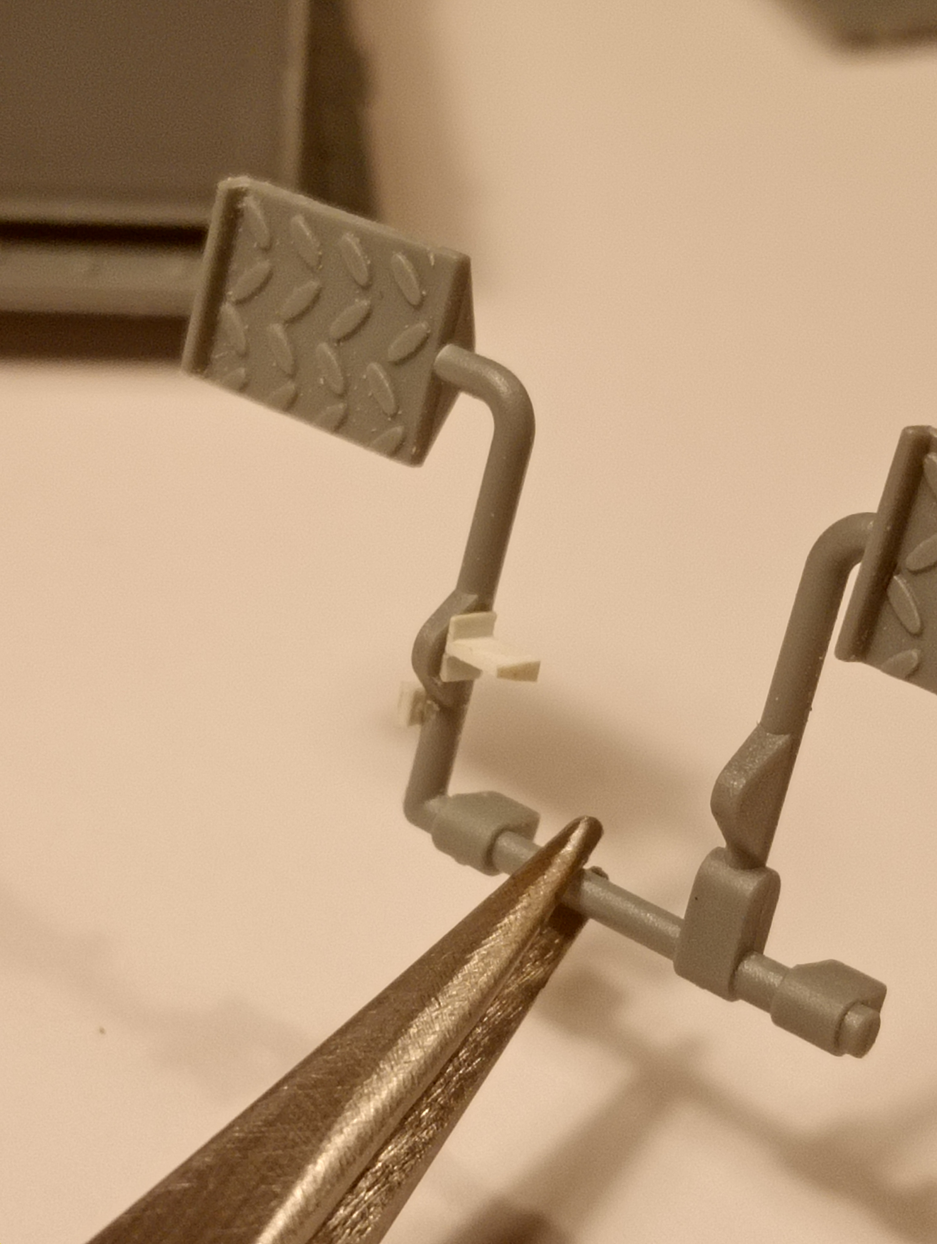
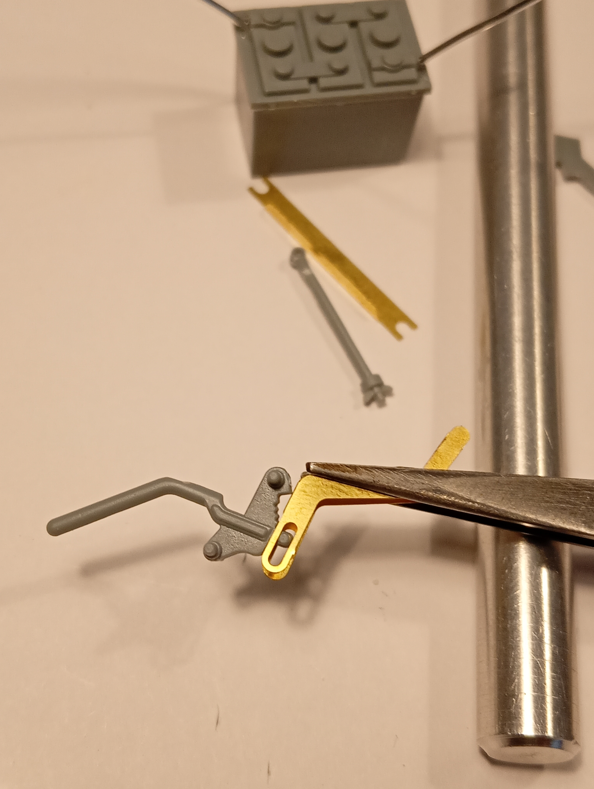
This is the return spring anchor point on the pedal frame on the outer LH side
And the double mounting point for the 2 cables on the inside edge.
On closer inspection for the cable mounts on the pedal frame, I realised they were to high up. So I carefully sliced them away and remounted lower down. Looks better now and closer to the ref photos.
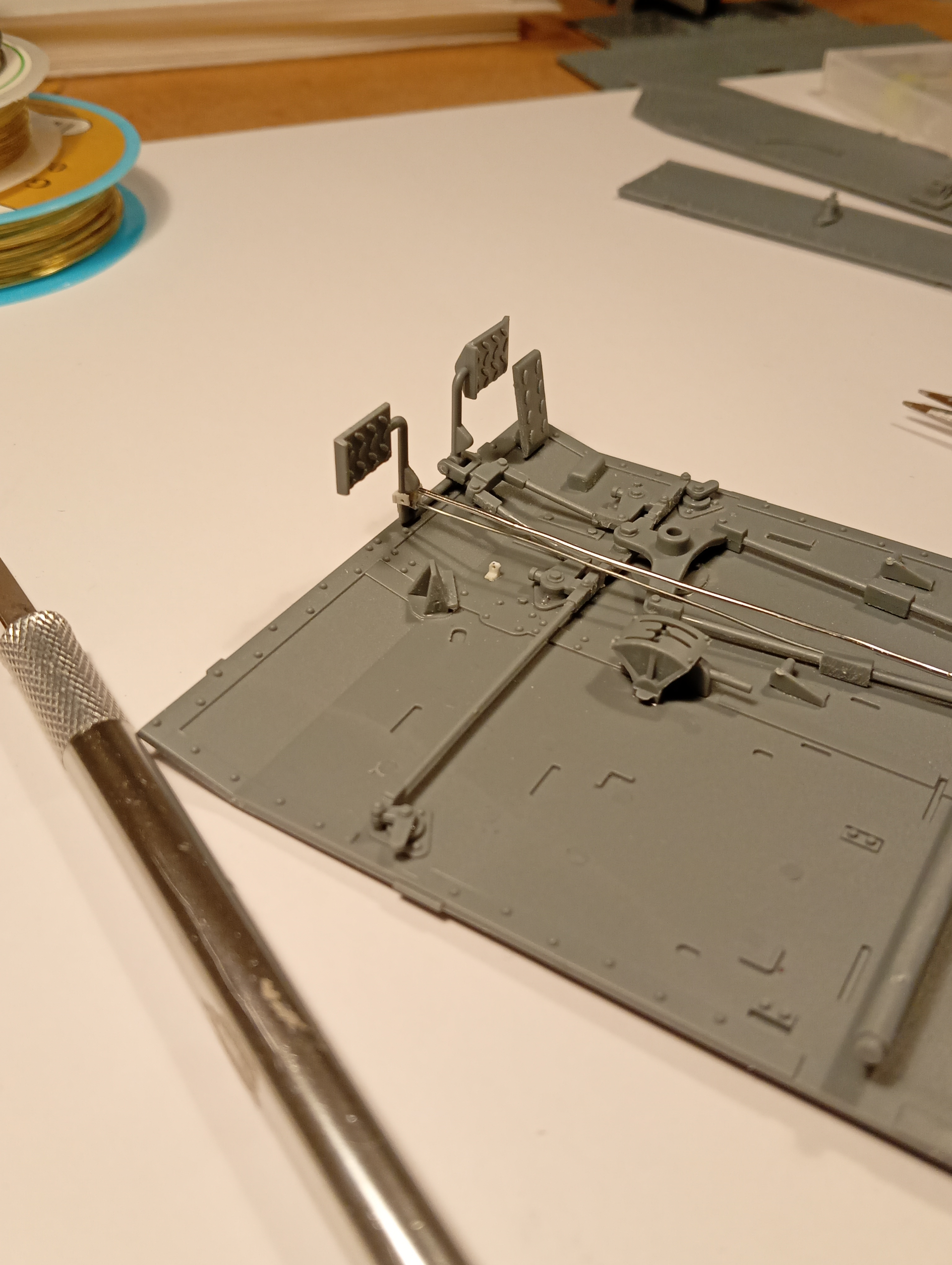
Dry fit of pedal frame and the cables dry fitted plus the floor mount for the return spring.
I have also re straightened the cables .. happy with this little bit of detailing as a starting point . As per the reg picture, … the upper cable is a bigger diameter than the lower one, so used the 0.8mm for upper, and 0.7mm on the lower.
Next up is fitting the RH side wall and the lower front plate and then I can fit the pedals and the return spring & cables.
The 2 cables and the return spring are fitted. Really like this simple detailing…. Adds a bit of genuine realism on a very open area.
That adds a LOT of realism John. well done! Love the spring.
Thanks Matt … appreciate it mate ….
Thought it best to add the cable detail to the battery ,. Not sure if the cables would be black and red like nowadays, but I will go with those colours for a bit of a visual draw in that area.
Thinking about giving it all a coat of the SCC No15 to get everything covered .
Nice job thus far John! Also have to add that you do very nice build logs. Always lots of clear and close photos for each step. It’s appreciated!
Thanks Sam, and very kind of you to say so…. This is also so Andy ( the chap I work with, who’s Grandad was on the carrier) has a clear picture of the build and each part or bit of scratch building that goes into it.
Have bent the battery cables to basically how I want them, and will paint that later prior to fitting as it sort of gets hidden away once fitted.
Some nice pleasing progress ….
You used to do great detailing in 1/35, but now in this scale you are really incredible… ![]()
Thanks Bert …. Nice to see you here ![]()
@Johnnych01 great looking build so far, really giving me the itch for a 1/16 scale build
Cheers Alex. This is the only thing I will build in this scale, so it will work well that its for someone else. This wouldnt be a bad one to do as a test one for someone, it will probably be about the same size as 1/35 tank once its finished (less barrel overhang) so its ideal for storing on a display shelf.
Beautiful detailing John, I particularly admire it when (after painting) your additions will be indistinguishable from the kit’s components. I’ve built a few commissions, I wonder if you’re also feeling any pangs that you’d prefer to keep it for yourself rather than hand it over? ![]()
None on this one as I’m looking forward to handing it over to become a small part of A’s grandads history along with his war records and medals. And thanks for checking in mate ![]()
I built up the drive sprockets and axle….. that will be fitted a bit further on….
The ends by the cocktail stick point needed a little sanding back as the fit with Cb13 when fitted was insanely tight, to the extent Cb13 wouldn’t turn.
They are connected to the sprue at either 7 or 8 points ….
If you’re building a Universal Carrier, there is no better reference then these 3 volumes. Not too much info on actual usage, but the technical side is superb. As you noted, lots of original drawings included with Volume 3 - it comes in a box!
Razor saw action!