Hi Frenchy - I just dropped in for a quick fly-by.
Thanks for remembering!
Mike K
p.s. Nice work Peter. Kudos!
Hi Frenchy - I just dropped in for a quick fly-by.
Thanks for remembering!
Mike K
p.s. Nice work Peter. Kudos!
You’re right, Kurt, pin 2010 probably is the one to the right of the hatch, operating the travel lock for the boom - I’ve already figured out how that works, so it “only” remains to whittle it.
As for the li’l one, the replacement of the molded-on thing will look good enough, so don’t lose time over it.
It’s just the way the crane shaft is held in the upper position that I’m still at a loss with, but I could always drill across the tube it slides in and stick in / pull out a piece of wire, with nobody being able to prove me wrong, so once again, don’t dig too deep, you’ve already helped me a lot.
Peter
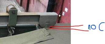
Here’s something that HB seems to have forgotten (I don’t have the kit…) It’s the lock - on the left - that secures the boom when it’s not used…
H.P.
Yes, thank you Henri Pierre, that’s what I think is “Pin 2010”. HB forgot it, Eduard made it, but their PE set is OOP, unfortunately. Your pic helps with a little detail, so thank you once again.
Peter
Just realized I had already posted this one in your HST thread on the old forum… 
H.P.
You’ve got a remarkable memory - I can’t even find that thread any more!
Peter
He’s got it all in a database, cross-referenced 12 different ways …

Unfortunately not, but Google is here to help. I just did an image search for “frenchy armorama HST” … et voila ![]()
https://armorama.kitmaker.net/forums/285974
H.P.
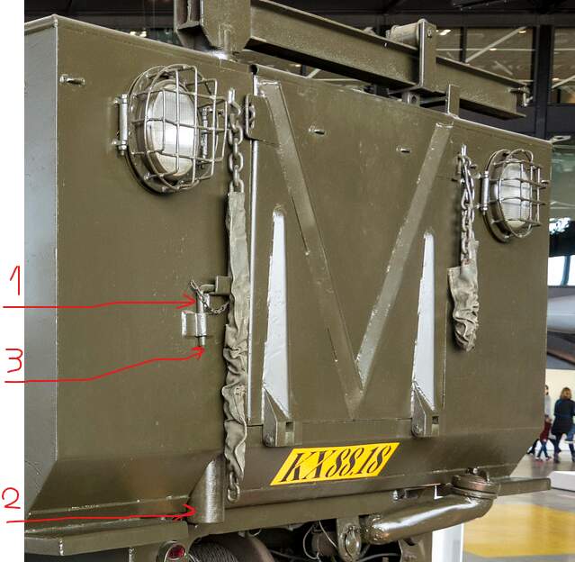
Hi Peter:
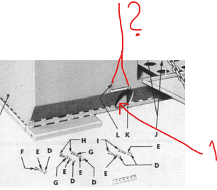
The TM doesn’t have a lot of detail but it appears that the L-shaped pin on the back of the box goes through a hole and through the pipe, and the hoist shaft sits on top of it. The hole would be about where I have shown
This would let the pin go into the hole with the leg pointing up. The pin would rotate in the hole counterclockwise, and the leg would fall behind the clip to keep the pin from coming out.
That’s how I would design it, anyway.
KL
The pin seems to have a rounded corner though, as if it was shaped by bending round stock in a 90 degree angle. A round cross section makes it easier to rotate in the hole and avoids the “square peg in a round hole” idiom …
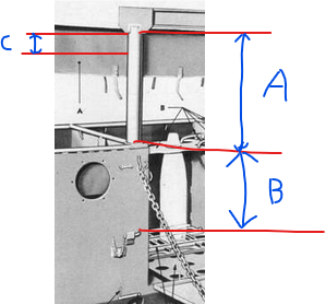
The crane pillar needs to extend distance A below the pin hole. Distance C is close to zero.
The stowed crane pillar probably extends down through the hole marked by 1.
I wonder what L and K do when they’re working
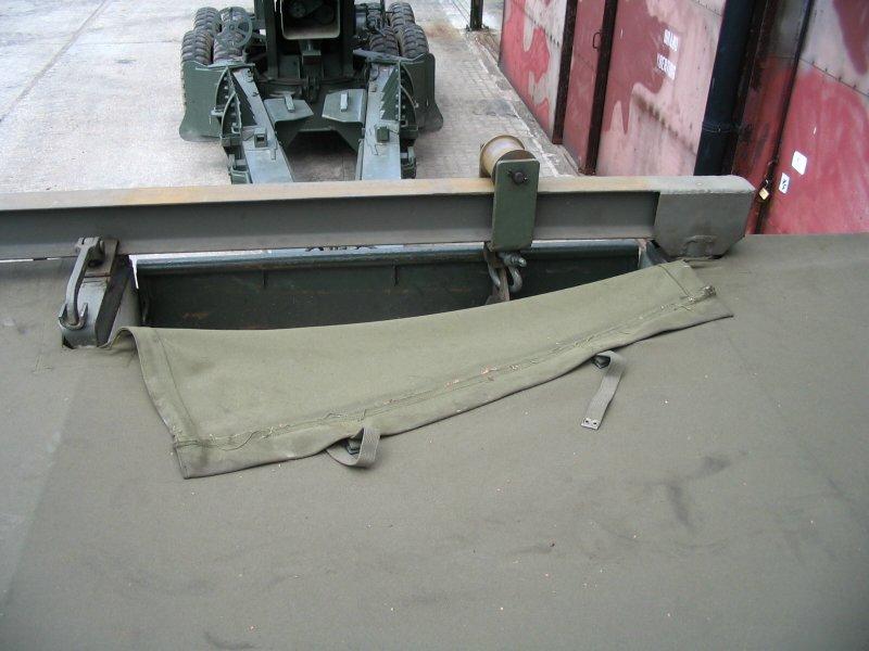
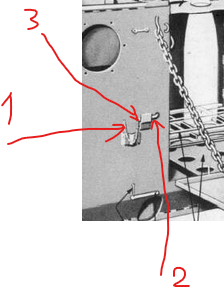
Found the photo:
We all know now that there’s a hole missing on the HB kit, but here’s a picture of it anyway…
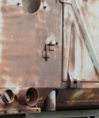
H.P.
EXCELLENT Frenchy 
Wow, gents! Now that’s what I call team work, thank you all very much.
To sum up your findings:
Where the kit constantly lets the guide tube protrude at the box’s bottom, instead, the pillar comes out (only) when the crane is stowed.
The hole for the lock pin is hidden by the hatch chain most of the time.
The lock pin is bent from round material and with its pointed end goes into the guide tube to support the lower end of the raised pillar, this part of the pin appears long enough to pass right through. The securing chain is fixed to the pin’s other end.
Now all that’s left for me is to transform all this into plastic …
In the meantime, I haven’t been idle, either: I figured out construction and mode of operation of the crane lock - the thing at the very left in the photo Frenchy contributed. In the first TM illustration of the crane that Kurt has shown, parts C,D,E belong to it, and I’ll show and describe as soon as I’ve got it all together. Which I hope will be soon.
Peter
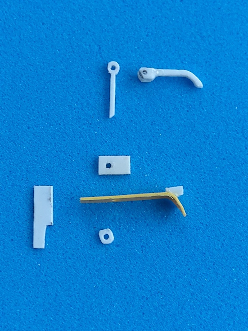
Well, a deep cut in the tip of my right hand index finger doesn’t really help in modeling. Luckily, I had done most of the work on the crane boom lock before that happened, so I can show an “exploded view”:
Parts K and L are the tailgate hinge pin and locking cotter pin, respectively.
KL
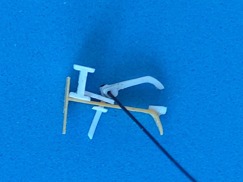
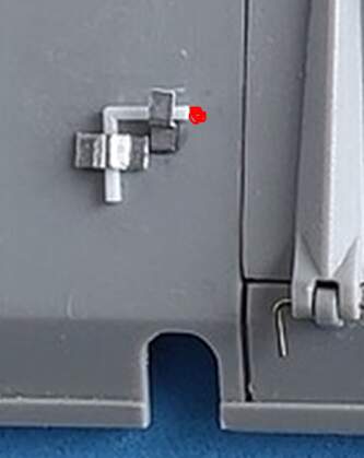
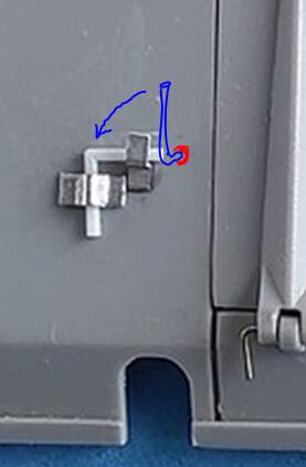
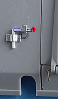
As promised, now here’s a dry fit of the crane lock’s parts (please also refer to the exploded view above).
And it works like this: The “needle” that’s hinged to the handle has a square cross-section and goes through a square hole in the rectangular plate. Thus, by moving the handle sideways, the plate can be moved over the lower flange of the boom or away from it. Depressing the handle exerts pressure on the plate, and the handle’s other end is kept in place by a piece of half-pipe that it rests in.
This should be all there is to know about the M4 HST’s crane and its chain hoist, so I’ll report about further progress in my WIP post on Hobby Boss’ kit. Thank you all for your interest and especially for your help without which I’d still be sitting here scratching my head!
Peter
PS: The hole in the yellow part is round, so the (to be shortened) needle can freely turn in it,.
Man I LOVE scratch build engineering solutions!!!
Thank you, Tom - but things like these are what keep me busy with a single kit for more than a year!
Peter
In a word… Wow… 
Thanks, Paul. The real challenge was finding out what the thing looks like, then figuring out how it works. Once that was understood, cutting and sanding plastic was standard Optivisor work…
Peter