The Hobby Boss M4 High Speed Tractor (large caliber ammo) is driving me nuts:
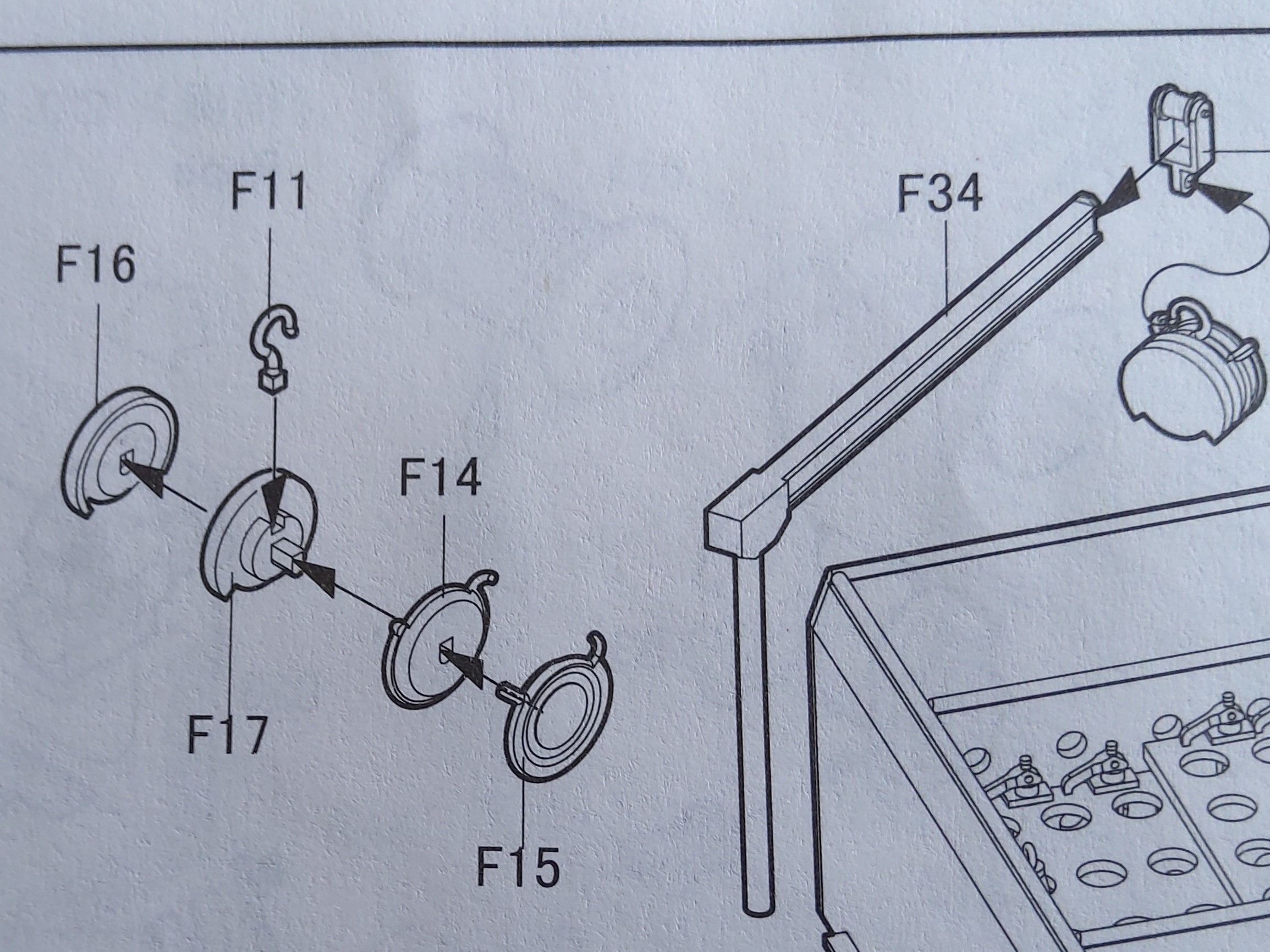
So it has a chain hoist representation, composed of four equally thick discs plus mounting hook. An endless operating chain and another chain with a load hook are to be added.
What puzzles me is that the load chain can not be installed below the mounting hook, but has to go as far beside it as the other one on the opposite side. That would lead to severe canting of the whole thing when carrying a load, and to me the prototype photos all seem to show the load chain right below the hoist’s point of support. It appears to have one end fixed to the hoist, hanging down in a loop, then going up over the center and down again to the load hook.
Can anyone please explain how to reproduce this on the model or lead me to a photo that would give me that information?
TIA,
Peter
1 Like
Ones educated guess is the on one side of the hoist is the drive chain located, while on the other side the load chain. Aren`t there any walkarounds of the M4 HST around?
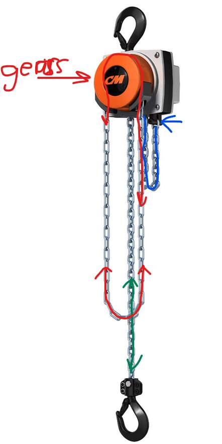
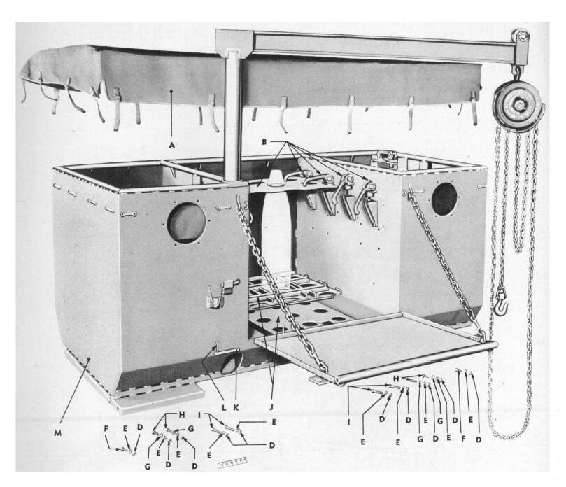
A modern version of this type of contraption:
Pulling the red chain will make the load/hook go up ur down.
The red chain is an endless loop working on the reduction gear behind the letters CM.
The green chain with the hook goes up or down controlled by the reduction gear powered by the red endless loop chain.
The bight of blue chain in the background is firmly hooked, blue arrow, to the housing. The bight grows larger, lower point comes down when hook goes up and vice versa. When the loaded hook has gone all the way down the bight will have disappeared. The green chain becomes the blue chain when the hook goes up and vice versa ahen the hook goes down.
Can’t say how this would translate into the parts provided by HB
2 Likes
Maybe the pics posted by Michael in this old thread would help as well (even though it’s probably not the very same hoist…) ?
https://armorama.kitmaker.net/modules.php?op=modload&name=SquawkBox&file=index&req=viewtopic&topic_id=238652&page=1&ord=1
H.P.
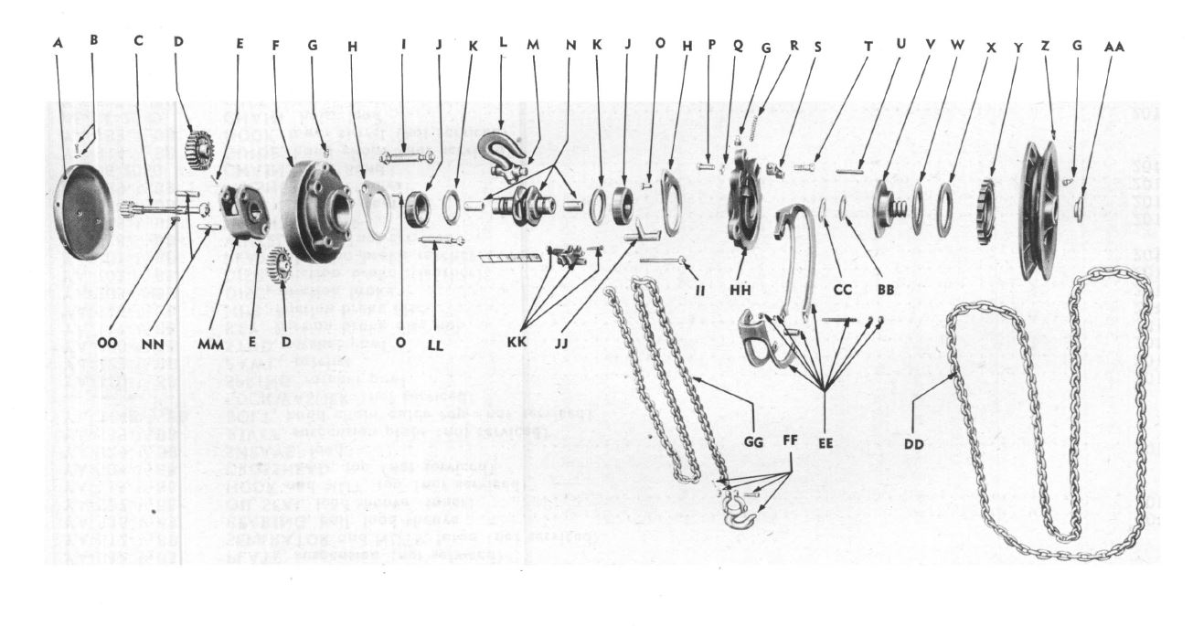
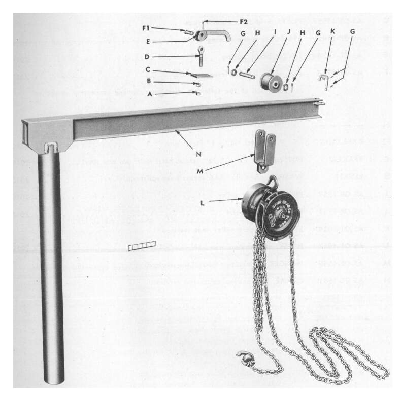
The hand chain is a loop around the handwheel at the far end of the assembly. The hook is over the load sheave, not attached to it as the instructions show. The hook had a short cross bar at the bottom, making it an inverted T shape, and was attached near the top. The drum on the end opposite from the handwheel is the gearbox and has no chain coming from it.
So, imagine a dumbbell. There is a loop of chain within one weight, hanging out at the bottom. There is a chain anchored between the weights that hangs slack and then goes up and over the handle, with the chain hook hanging. There is a bar between the two weights at the top. The hoist hook is attached to this bar. There is space above the chain hanging over the handle and the bottom of the bar at the top.
KL
1 Like
Thank you all for your help! Kurt’s explanation confirms what I thought I had figured out studying Mike Koenig’s photos, so now I can start working.
Happy modeling,
Peter
Part F11 shall be attached to a cross bar between F17 and F14.
The central part of F17, where HB wants you to attach F11 should be
The hoist chain with the hook goes bla bla bla bla.
There is a proverb that says a picture is worth more than a thousand words …
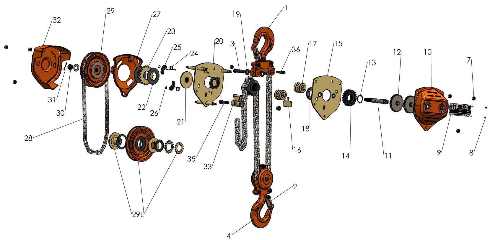
This assembly diagram is for a modern one but the principles still apply.
I found it here:
2 Likes
I just hope you don’t expect me to rebuild those 5 HB parts into something like you’re showing there, Robin! Thanks anyway, as it helps to understand things even better.
Peter
I started trying to convert Kurts essay into something referencing the HB parts and realised it would be too difficult to describe the chain cogwheel so I went hunting for images instead.
You need to change F11 slightly and create something to act as part nr 33 in the diagram I posted.
Part 29 in the diagram is either between F15 and F14 or between F16 and F17.
The rest is optional 


Jeez, the hoist is a model for itself.
You’re SO right, Hermann, and things aren’t made easier by HB giving the parts for the operating chain wheel (Z in the diagram shown by Kurt, F14/15 in the kit) with a smaller diameter than the reduction gear housing (A+F and F16/17, respectively), whereas diameter sizes are the other way round in 1/1.
Still brooding over that one…
Peter
Just give up and start cutting styrene.
You know you will not be able to use the HB parts now that you know what it should look like so you might as well admit it now and get it over with 
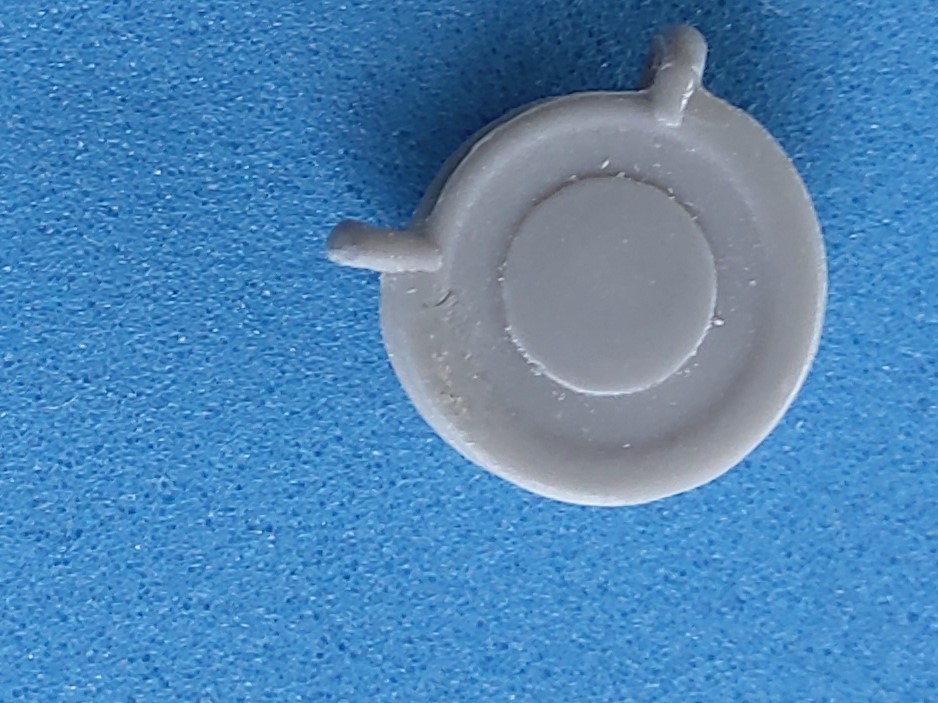
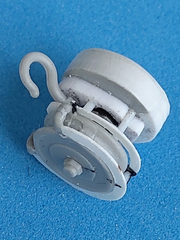
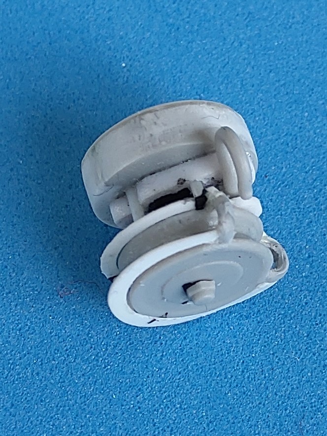
Give up? Not so soon! Here’s what I made from the kit parts:
F 16/17 had their “notch” at the bottom filled and an added 1mm plate on the outside sanded into a dome. The mounting plate for the hook was replaced with a larger 1mm plate that received a hole at the top. Opposite this, F 14 received a 2mm “geared” rod above which a 0.5 mm extension with a hole completed the mounting for an 0.5mm rod that goes through the hook’s base, leaving it free to cant. Another four pieces of this rod join the halves of the hoist. F 14/15 had the molded-on “operating chain protectors” removed, and crescents from 0.1mm sheet make this wheel optically larger, with a hex-head nut adorning its center.
I think that’s “close enough for government work”, as they say.
Peter
3 Likes
Excellent work on salvaging the HB-parts 

Actually, it was less the wish to salvage the parts than the lesser amount of work compared to cutting everything w/o exact measurements and all!
2 Likes
It’s all a matter of making intelligent and rational decisions
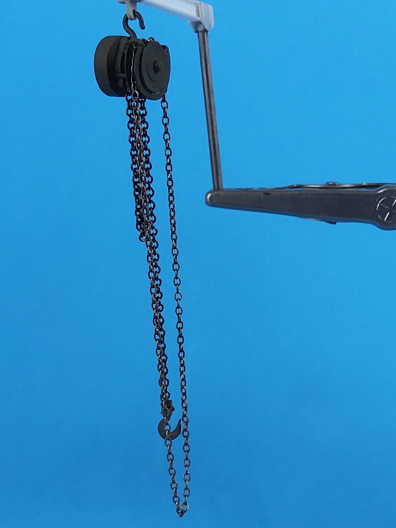
Hi Kurt,
Thanks to your explanation and the exploded view you supplied, I’ve been able to cobble up a more correct model of the chain hoist:
But now I need help again. HB stipulates mounting the crane in the working position, i.e. with the mast fully exposed. To this purpose, the “tube” that the mast stows in isn’t a tube, but only has a 5mm bore at its top. I’ve drilled it through (to also show the crane stowed) and now am at a loss to mount it erect. I could imagine a pin pushed across the tube’s diameter below the mast, but can find no evidence for this. In the Tankograd book, that thing to the left of the hatch on the outside is called “Lock Pin”, but it’s stowed so far away that it couldn’t serve to arrest the crane, and besides, I can’t detect a hole for it to go into - what’s that thing for, anyway?
Thanks a lot in advance,
Peter
1 Like
Hi Peter:
My TM is on paper so I’ll have to look at it later, but the hoist shaft was just a pipe.
ISTR that that pin has something to do with the hoist, but I don’t see anything obvious either.
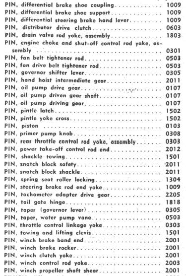
There are quite a few “pins” in the parts list, so it is not easy to sort out. It’s NOT the one in yellow, unfortunately.
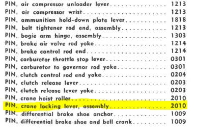
KL