Where does one find plans for things like M4 Sherman wading stacks?

Where does one find original plans for things like M4 Sherman wading stacks, mine clearing flails, rocket launcher assemblies, and similar things? (I remember asking a similar question more than a decade ago.)

Obviously, drafting artists and the people at model companies have access to this information. Is it coming from technical manuals? Are they looking at pictures and guessing? Is there a super secret repository of blueprints available to the public? Are they measuring museum vehicles? Is there a secret cabal of model designers who kill anyone who tries to learn their secrets?

This is a real mystery to me. No one ever talks about it. The answer is usually, “Just buy after market thingy X.” Okay. How did the person who made after market thingy X get accurate plans?

3 Likes

US Army archives would have such plans somewhere. At least for US built variants such as wading stacks, T34 or Whiz Bang rocket launchers, etc.
The British variants such as the mine flail Crab likely would have their plans in Ministry of Defense files somewhere…

2 Likes

Thanks!

Archive.org has a US Army Manual Collection with about 600 documents. I just downloaded manuals for the M24 and M47 tanks. That’s a start.

3 Likes

Good, top of the line museums. For example, the Tank Museum, the old Patton Museum, Imperial War Museum, and others, will have lots of documents in their archives. They may also have what you are looking for in their museum, and if you are nice, can get measurements from the real item. Contact them.
Ken

2 Likes

Nothing to do with this company, just a happy customer. Their reprints of Technical Manuals are first rate and this one may get you closer to what you need:

Frank

2 Likes

The Army doesn’t have an archive of drawings, or most documents. The US National Archives and Records Administration (NARA) is responsible for holding documents of this period. However, the documents must have been given to them in the first place. The vast majority were not.

Technical documentation like drawings was created by a large number of organizations. Some of them kept their drawings, some didn’t, some were transferred, some were sent to NARA. Fording gear was developed by Ordnance Tank-Automotive Command so it would’ve been kept by them, if anywhere. Much of what they had from that period was transferred to the MVPA. They don’t have it cataloged, and don’t have it available to the public.

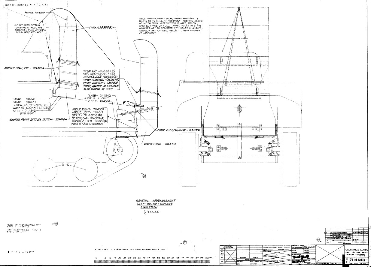
People must also come to grips with the concept of how drawings are organized. In this case, there will be a drawing showing how the stacks are installed on a tank. It will refer to other drawings that depict the intake stack assembly, the exhaust stack assembly, the adapter assemblies, and so on. The installation drawing will not have any useful dimensions for us. The assembly drawings (all separate drawings) are unlikely to have many dimensions useful to us, and will not have dimensions or material thicknesses of the parts going into the assembly. The assembly drawings will reference subassembly and part drawings, and subassemblies will reference part drawings. That’s where you’ll get dimensions, but typically only for a single piece of metal. So, between this:

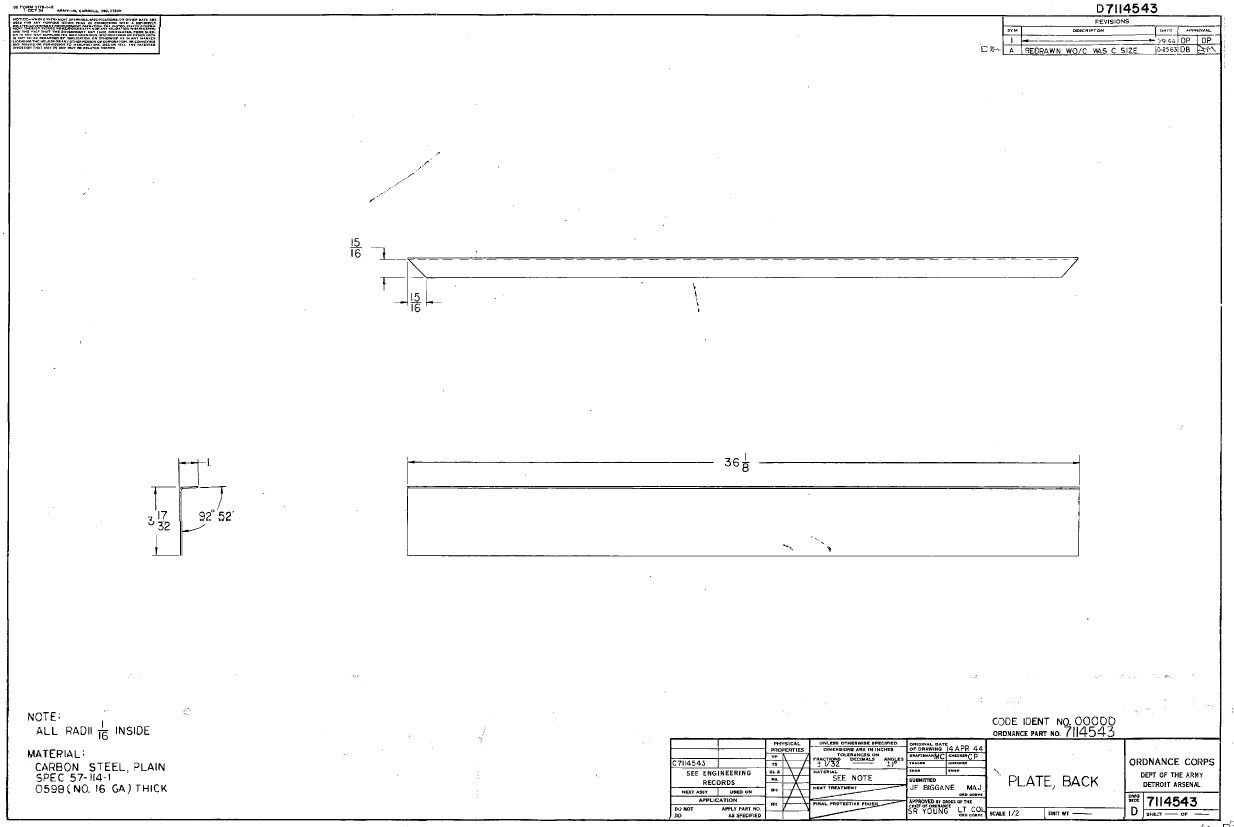
and something like this:

there are a LOT of drawings, an incomprehensible number of drawings to most people. And many of the links in the chain are missing, so the path from Part G to Assembly M can’t be determined. And if you are not an engineer, drafter, machinist, etc., you’ll probably never figure them out.

I’m sorry, it took me a few minutes to recover after guffawing over this and falling out of my chair.

No. They will show how things work, fit together, and come apart. They don’t have design information.

For the most part.

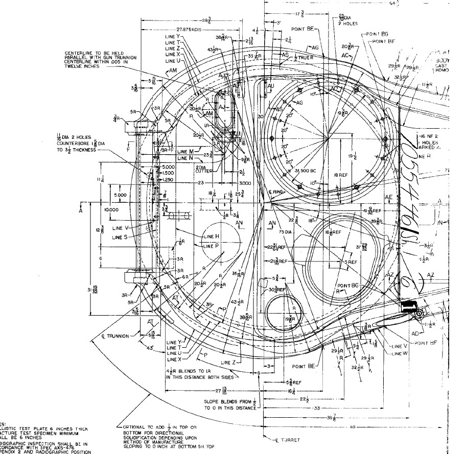
Some times. A little. Another thing to remember is that real objects are made of many dimensions, some of which locate objects in space or are inaccessible on the assembly. For example:

This is one half of one sheet of the drawing that defines a turret shell casting. Do you think it’s going to be possible to measure enough places on a preserved vehicle (assuming one exists) to make an “accurate” model?

They didn’t. You are fooling yourself if you think they did. By far, they make something that sorta looks likes the pictures and fits onto an existing model. If that model is wrong, the aftermarket is made to it, not to correct dimensions.

KL

7 Likes

Kurt speaks the truth. Nobody ever took action to provide for the needs of aftermarket producers decades down the line. In most cases they didn’t even provide for the historical record. The drawings you want were located at the manufacturers who made the parts, and when the part orders stopped coming, they had very little incentive to preserve anything. As Hilary Doyle told me : you go to visit them to look at their records, but if you arrive in the car park and the building is a modern building, they won’t have what you want.

Right now I’m reconstructing diagrams of the Tiger. Most of the originals no longer exist. Recently a handful of wartime drawings came to light somewhere, stored away because they were designs for potential changes that got cancelled. Some of the dimensions and shapes on those diagrams are the cancelled items, of little interest to me, but in the interests of making things fit they also show some of the real tank. That data is like gold to me.

David

5 Likes

Note also these drawings were considered secret at the time they were in use, and then a few years later became waste-paper when tank design evolved and the subjects of the drawings went out of production. Chances are most of them went in a skip during a clear-out of the drawing cabinets once they were obsolete, without ever getting any “public” circulation that might lead to preservation.

3 Likes

Sounds about right. I guess that why I do most of my modelling ‘by eye’. If it looks good, hopefully looking like a photo, then it is good!.. Works better with braille scale though I must admit. You can get away with a bit more vagueness there :slight_smile:

In the case of building the fictional tank from Indiana Jones, I had to draw up plans of my own from various views and a stated length of the vehicle.

2 Likes

That’s not correct. For the most part the drawings were considered RESTRICTED, which under today’s lingo translates as FOR OFFICIAL USE ONLY, even for items that were CONFIDENTIAL or SECRET. The RESTRICTED category would’ve meant that the drawings were not to be given to the public but their handling and storage was more or less like any other office document.

KL

1 Like

Minor detail! The point is they weren’t freely available outside the close circle of the factory and the client, and nobody was archiving them for us modellers…

David has the added complication of the Germans losing the war, having various factories bombed, and surviving documents combed through by the Allies!

1 Like

Thank you for all the advice and information, especially with regards places to look for information.

Since yesterday, I downloaded about 30 US Army artillery and vehicle technical manuals, including one for the M1 and M1A1 Dozer Blades, which is a good start. My original collection of such manuals was lost many years ago. While not plans, they contain useful information and many interesting drawings.

Thank you! I completely forgot about Easy 1 Productions. That seems like a good place to start for the wading equipment.

The Tankograd TM series of books are excelelnt for reference as well. Many photos and drawings that look to come from both the original TMs and ordnance design blueprints.