I hope that all of you visiting are having an enjoyable, safe and wonderful Christmas holiday weekend.
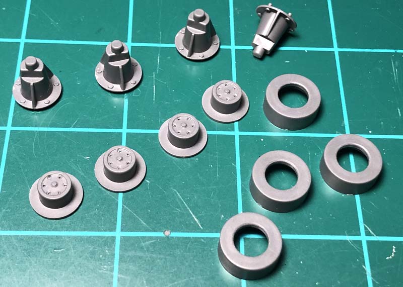
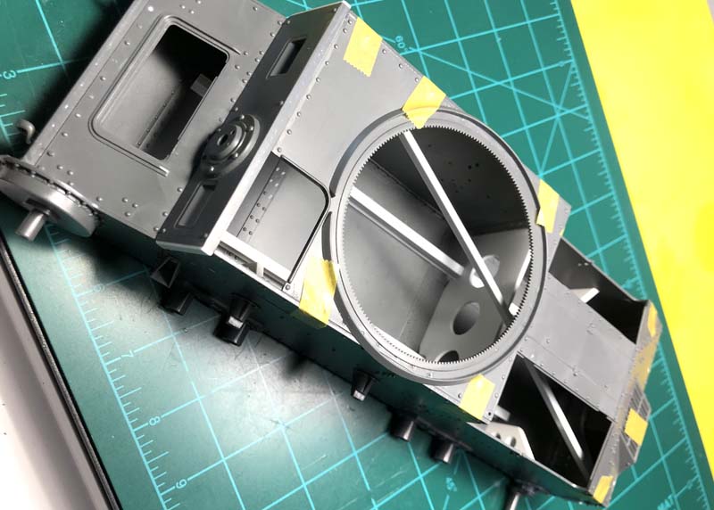
The kit box features list or the instructions do not indicate that the suspension is workable. But because all of the suspension parts come as separate pieces, with careful attention to assembling these components, the suspension can be made to work as on the real vehicle.
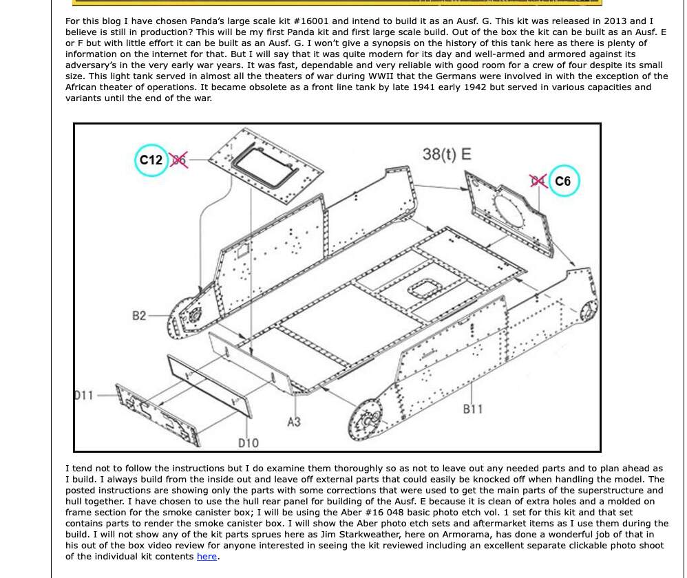
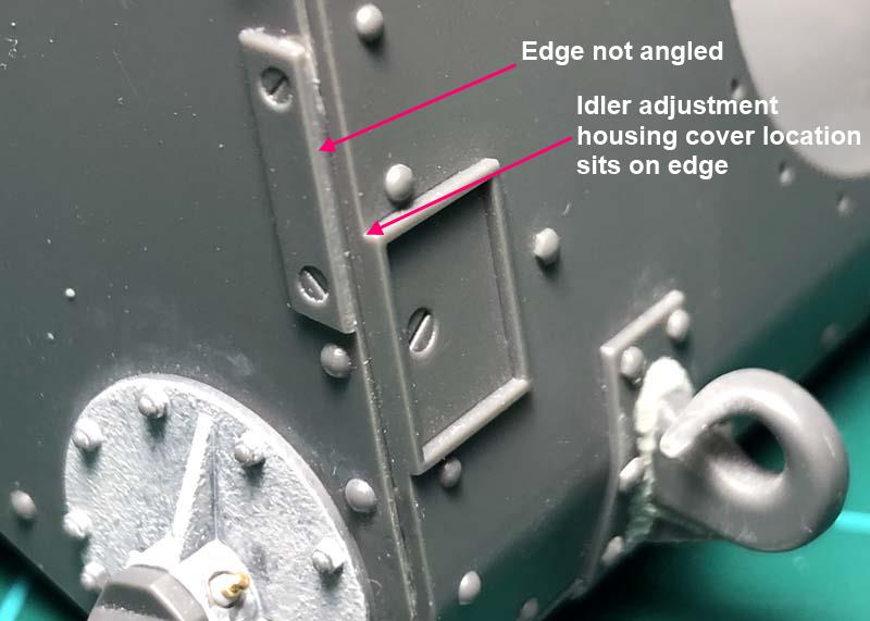
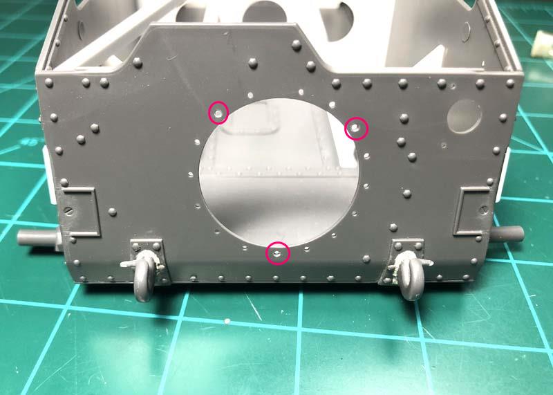
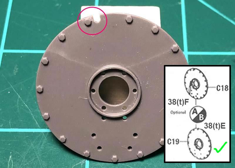
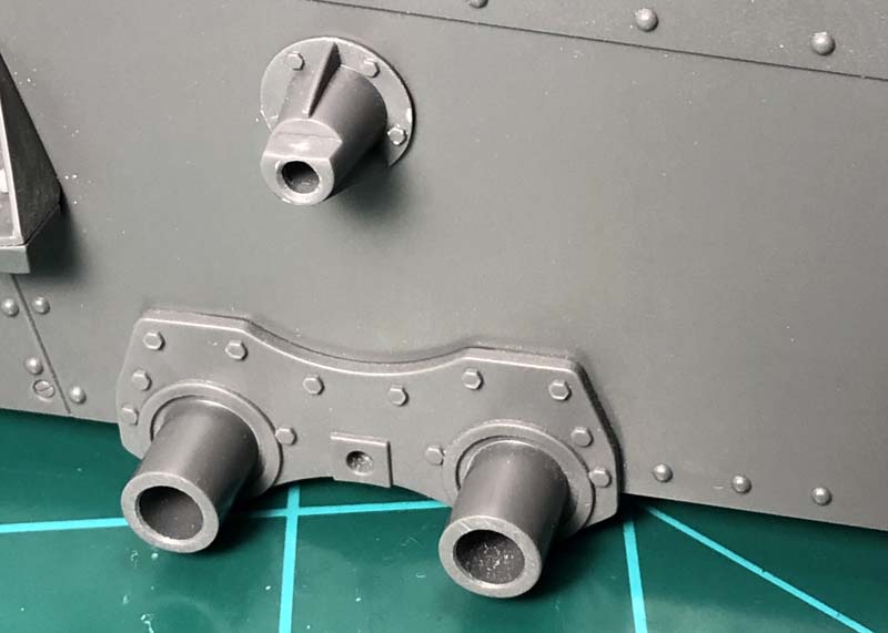
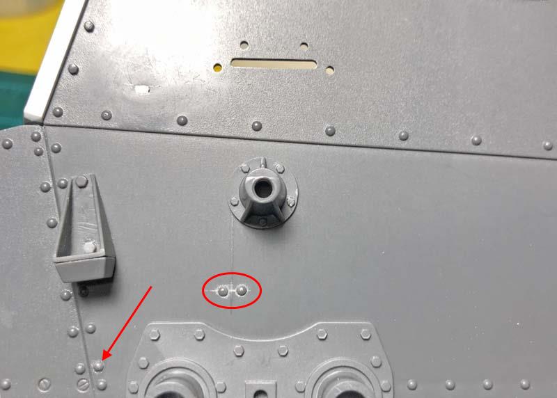
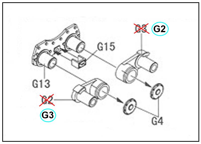
Here I have identified several of the parts that are mislabeled on the instruction sheet.
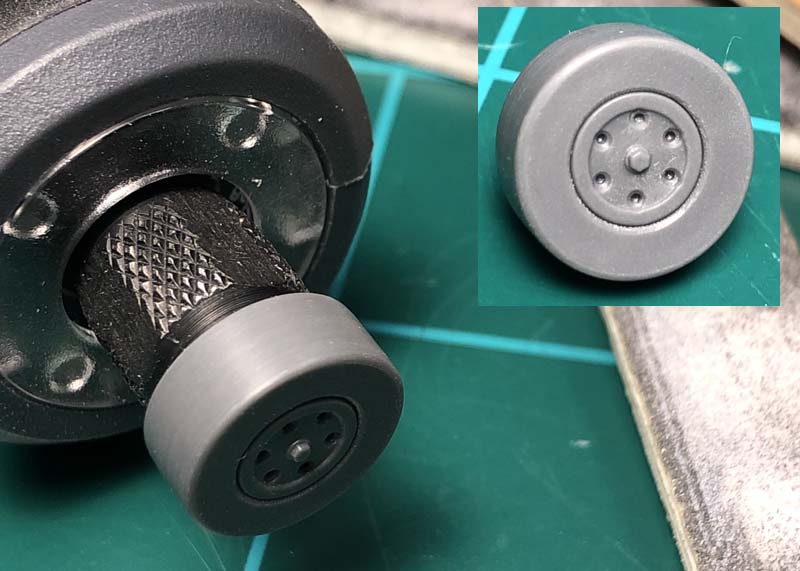
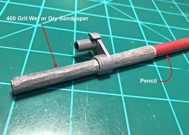
The fit of parts G2 and G3 over the shafts of part G13 was much too tight and wouldn’t allow for any movement. So I resolved this issue by rolling a piece of sandpaper to sand open the inside of the swing arm housings. I supported the sandpaper by using a pencil. The pencil does not fit into the housing but keeps the sandpaper from collapsing and holding shape during the sanding process. By numbering each of the parts I could easily fit each part to the same location again.
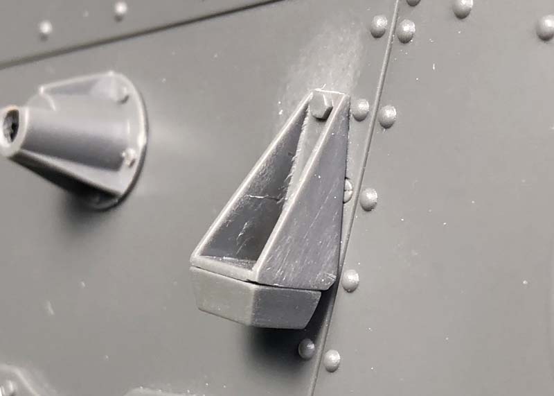
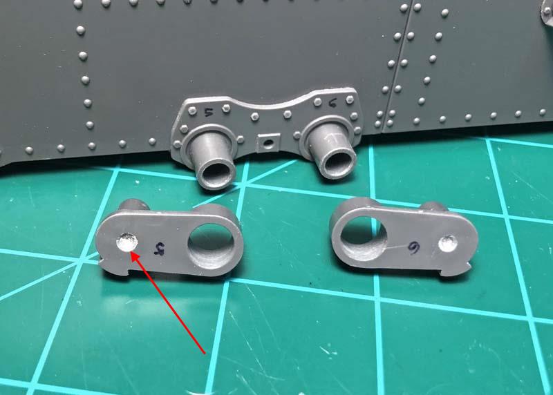
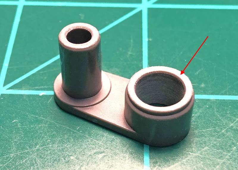
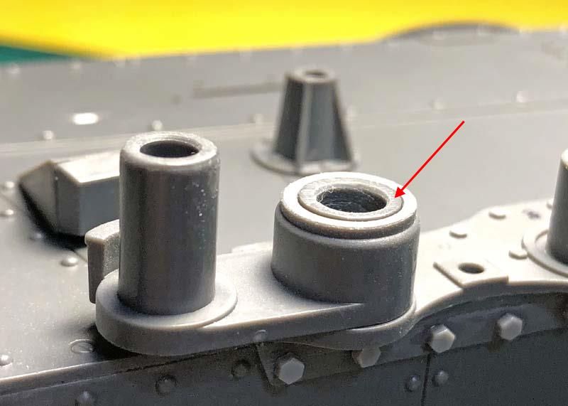
Here you can see an example of the numbering. I created a shallow concave opening, as seen on some of my reference pictures, on the backside of the swing arm housing. I stepped drilled and used a small grinding stone to even out the drilling and then smoothed this out by applying liquid cement. The sizes I used for this were a .095" (2.43mm) and .115" (2.92mm) diameter drills.
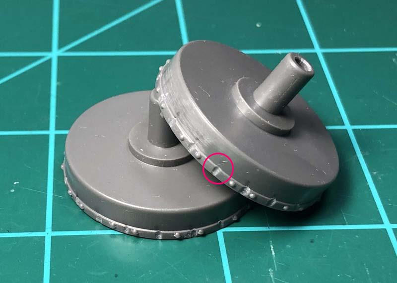
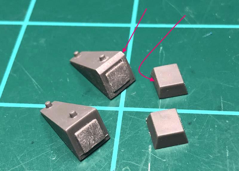
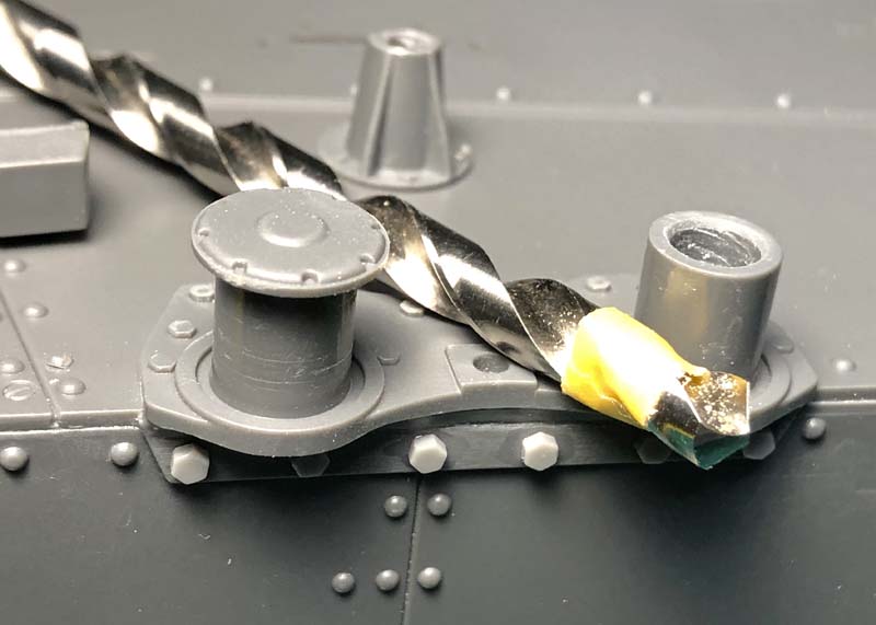
I needed to reduce the height of each of the swing arm housings so that the housings would sit just slightly below the height of the shafts on the swing arm chassis supports. The second picture shows the shaft sitting just proud of the swing arm housing after reducing the height by using sandpaper affixed to a flat surface.
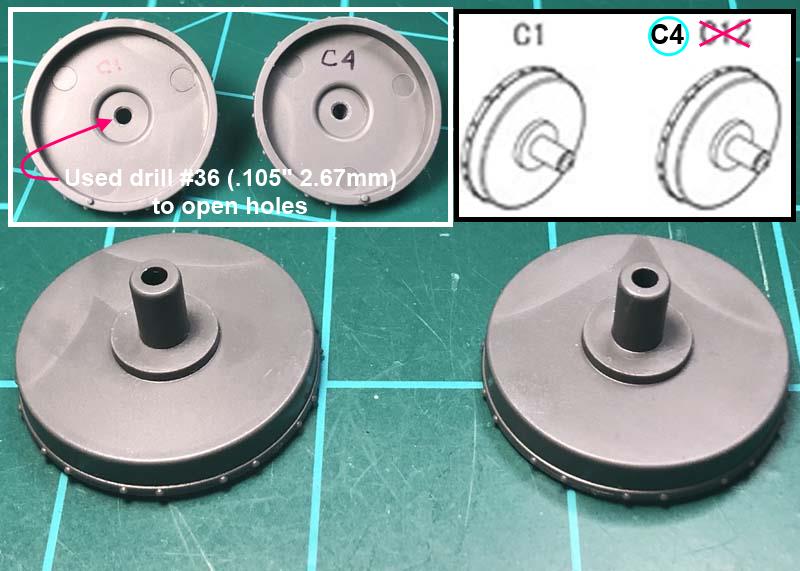
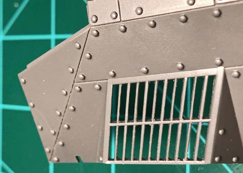
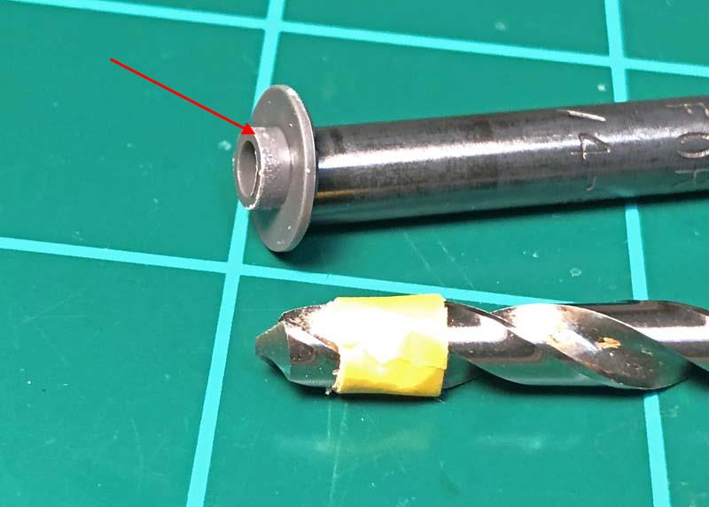
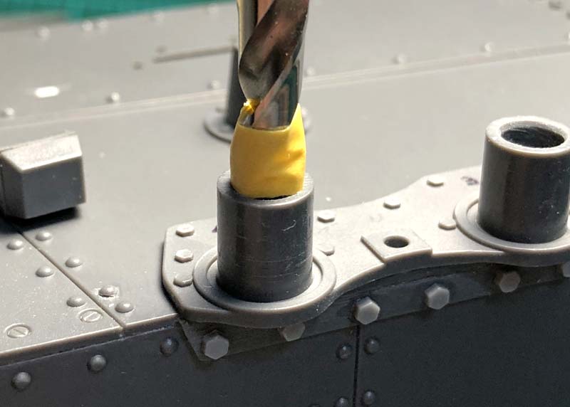
On parts G4, swing arm housing plates, the locating bosses, where much too large in diameter, to fit into the openings of the swing arm chassis support shafts. To remedy this problem I used a .202” (5.13mm) diameter drill. I warped a small piece of tape to the end of the drill just enough to accommodate for the depth of the locating bosses to fit them onto the shafts. With the swing arm housings in place over the shafts of the swing arm chassis supports and once the swing arm plates are cemented in place the swing arm housings should move freely without binding against the swing arm housing plates.
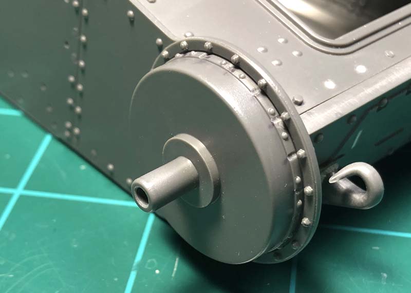
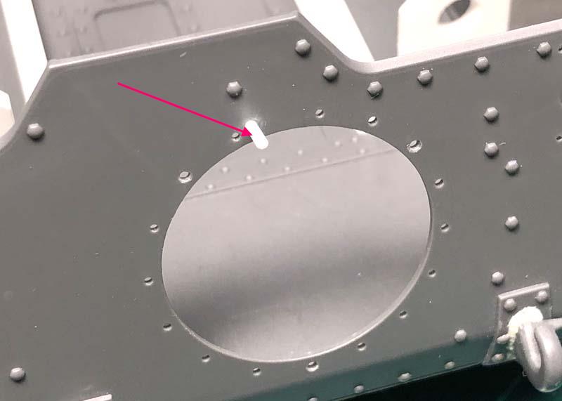
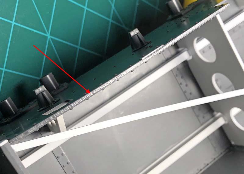
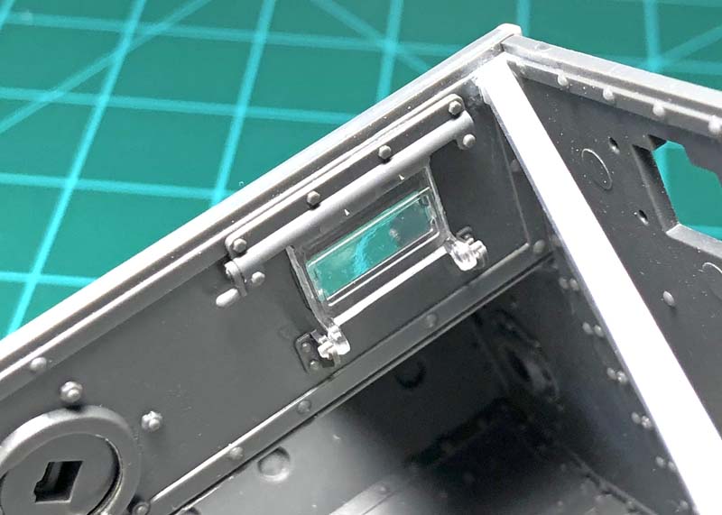
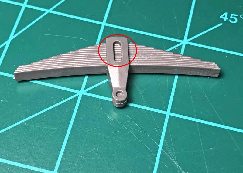
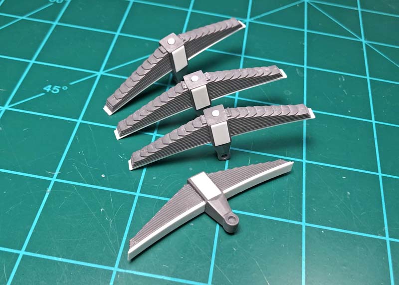
The semi-elliptical leaf spring sets that the Panda kit provides is almost correct for the Ausf. E/F models. However, there should be 15 leaf springs in place of the 13 leaf springs the kit provides. Originally there were 14 leaf springs and 15 for the late Ausf. E-G models. Also on the G models the oval aperture on the face of the leaf spring wrap around cap had a solid covering added over this opening. The extra leaf spring and solid plate covering were added to both help with the added weight of the extra vehicle armor and brakeage of the leaf spring caps.
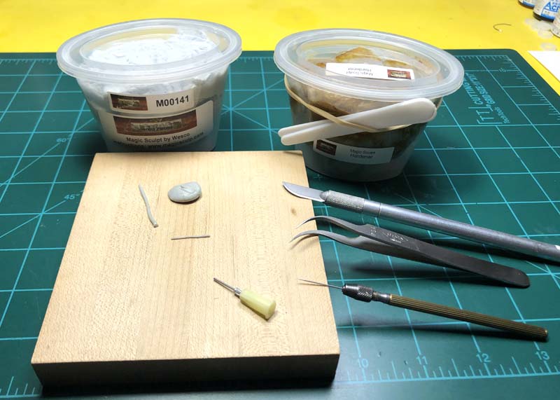
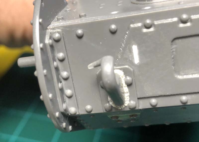
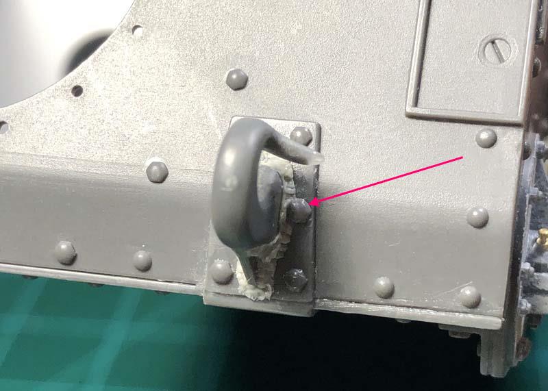
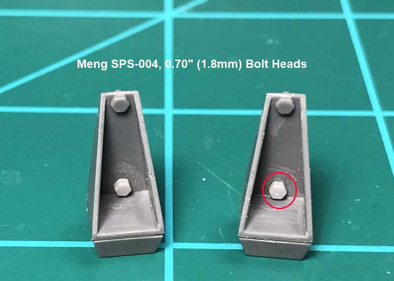
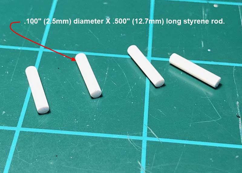
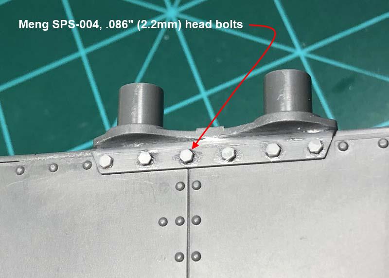
I added two new leaf springs using .015” thick (0.4mm) X .156” (4.0mm) styrene strips cut just a tad longer than the proceeding kit leaf springs. .015” thick (0.4mm) X .188” (4.77mm) X .348” (8.83mm) styrene strips were cut to simulate the leaf spring cap plates. A .020” thick (.508mm) X .081” (2.057mm) diameter styrene strip was used to simulate the rivet used to hold the leaf springs in place on the cap. I dapped on Mr. Dissolved Putty with a toothpick around the cap plate sides to simulate the circular like appearance of the welds.
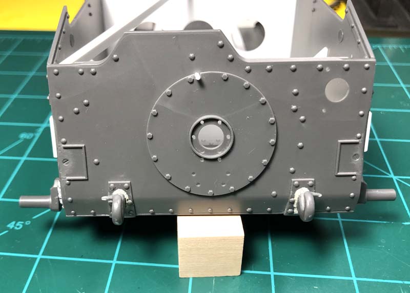
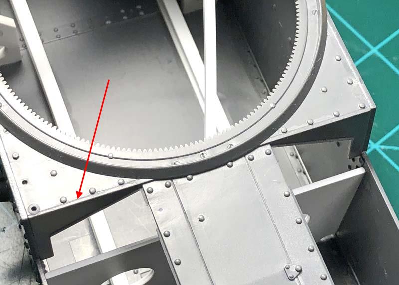
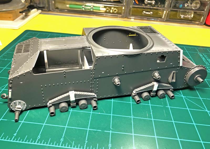
And finally a picture of the completed assembled, installed and workable suspension.
Thank you for dropping by to have a look, it’s much appreciated. See you next time.
~ Eddy