Looking very good! Will you scratch build parts of the interior or just close everything up?
Excellent step-by-step, Eddy! Really enjoyable to watch these large scale armor builds come together, keep it coming  I’ve always liked the look of these Czech built tanks, and this kit has so much more detail on the lower hull than any offerings in 1/35.
1 Like
Thank you for dropping by! I won’t be building an interior for this kit even though a small amount of parts are offered to address this deficiency. I have had this kit in the stash ever since it first came out hoping that an interior would be offered by Panda Models or as an aftermarket offering. Plus I don’t believe I am at a skill level where I could scratch one together.
Modelers law says that as soon as someone attempts constructing an interior for this kit it will somehow magically become available, something like that!
~ Eddy 
And thank you too for dropping by! Thanks for the kind words it is much appreciated. I agree with you in that this offering dose have a wealth of detail on the chassis. The nice part of this kit is that most of the parts are not intergraded and are offered as separate pieces. This gives anyone building this kit the advantage of creating a vehicle that is unique with some light scratch building skills.
Also there are so many pictures available on the internet showing a number of stowage and stowage box configurations for this vehicle but so far as I know many of these stowage items are unavailable in this scale for this kit. I have managed to find a nice set of fuel cans in this scale and will be using them for this build.
~ Eddy
Finally an update! This one is on the use of the Aber photo-etch fender set designed for this kit. The plastic kit fenders are good and have detail on them for placement of the supplied kit tools. A set of photo-etch fender brackets are supplied in the kit for these fenders, but there is no option for using plastic brackets.
I had decided earlier to use one of the available photo-etch fender sets in place of the kit fenders. I chose the Aber #16 049 German Light Tank Pz.Kpfw. 38(t) Ausf. E/F Vol.2 fenders, 1/16 scale update set designed for this kit. The difference between the fenders used for the Ausf. E/F and Ausf. G is miniscule. I will point that out here in the following photos below. I now like using photo-etch sets with my kits however this had not always been the case. I think that was because I had no experience, a process, or tools to make that journey easy to use this medium or how to apply it to my models.
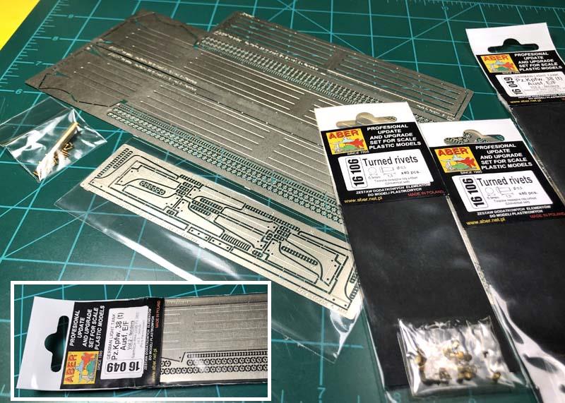
The Aber set comes with everything needed to add them to your kit. The exception is the use of rivets as this item did not come to use on the earlier models until the Ausf. G’s. This is due to a material shortage of hardware that accrued as the war progressed, I’ll leave it at that. Two sets of Aber rivets are needed for putting the fenders together to accurately replicate the model as an Ausf. G. Each set of rivets comes with 40 pieces each and in total 80 pieces are needed. You will still be short 8 pieces but I will explain why and what I did for the other missing 8 rivets below. The Aber instructions do not mention the Aber #16 106 turned rivets simply because the fenders are targeted for use on the E/F Ausf. models, but the instructions do mention making press rivets as an option. I went for using the turned brass rivets because of the added strength they provide when using them on through holes secured with super glue.
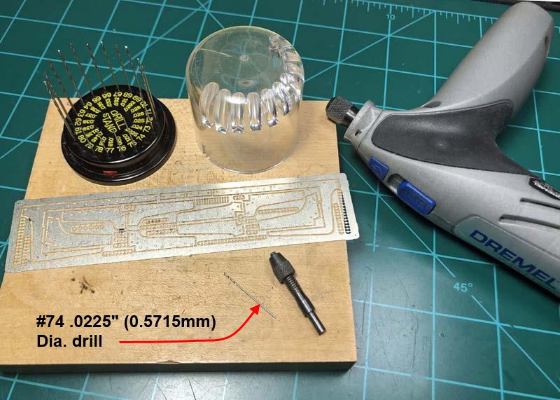
First thing to do was to drill through all of the holes on the fender brackets that are indented for pressing rivets. A larger drill bit chucked into a pin vise was used for de-burring the holes. This method of cleaning the holes was used on all of the holes drilled on the fender brackets and fenders.

Here the holes on the fenders have all been drilled. I also set about drilling a few larger sized holes on the fender brackets. I drilled holes where shown on 4L for passing wiring to the night head lamp and antenna cable and on 6L for passing the spare antenna. A spare antenna was not a factory item and was added as a field modification to some earlier and later model vehicles. A smaller hole was added on 4R for passing wiring for the horn. These larger holes should be placed next to the existing small holes already on the angled face of the fender brackets.
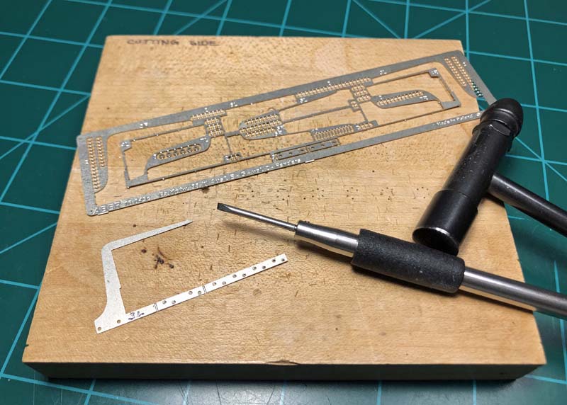
A small hammer and chisel are used to remove the parts from the fret.
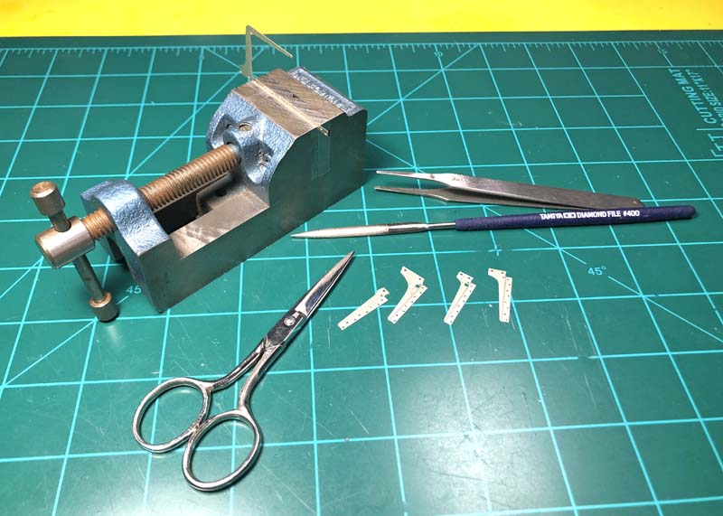
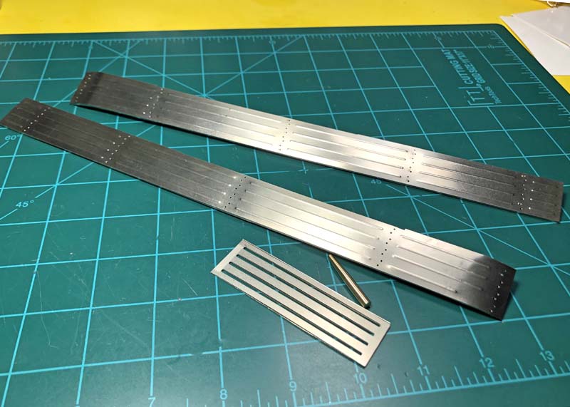
A small pair of stainless steel scissors is used to trim down the attachment points on the parts that are held in place on the fret. This is followed by using a diamond coated file to smooth out the nub held by your hand, stamp tweezers or a small vise. A 400 grit sanding stick could also be used.
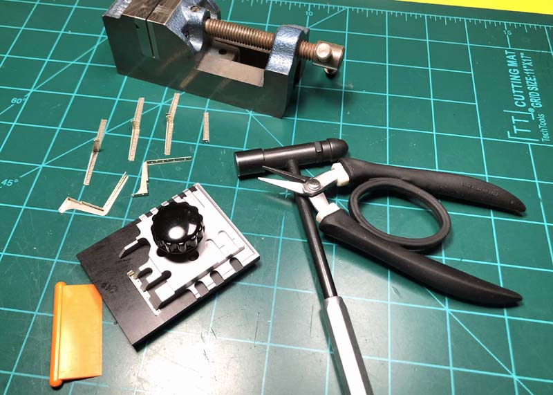
Some important tools to have on hand for bending photo-etch parts is a small folding tool and a pair of mar free pliers. The small vise with 90° cut edges also comes in handy for helping square up corners.
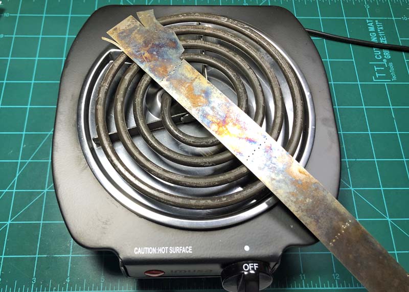
Photo-etch parts are an inherently stiff material; this is not always a problem except when you need to create rounded surfaces or completely rounded parts. You will need to anneal the material via a direct heat source to soften it and leave it flexible enough for bending without causing creases and keeping it from springing back. For this I use a small commercially made table top single electrical stove. Set the heat range to low and set the part on the stove until you see it become discolored from the heat. Then remove the part and let it cool down by itself.
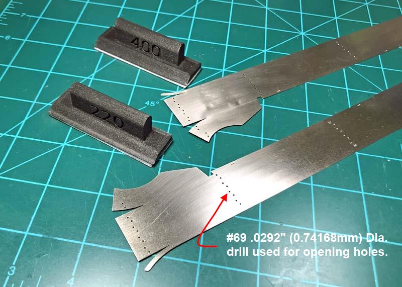
The part is now ready for creating the rounded front edges of the fenders and the reinforcing ribs but the part has become discolored and has oxidized in the heat process. I clean this up using two different grits of foam backed sand paper. This process has the effect of bringing the part back to its normal metal color and giving the paint something to bit on.
Before annealing the fenders I had drilled through the press rivets with a larger sized drill than the diameter of the fender brackets, this will assure alignment of the brackets with the already installed rivets.
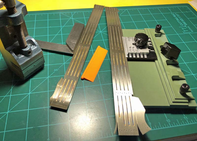
The fenders have three separate sections to bend on the inner area that meets the chassis. The center section is further away from the edge due to the 15mm added superstructure armor. This area was needed to be bent first a small amount at a time as the part was to long for my small photo-etch bender and too short for the longer bender I own. This was to prevent a crease from forming. The two outer sections are easily bent on the larger bender.
The section that is located on the outer area of the fenders was to long for even my largest bender and needs to be bent in sections to prevent a crease. However if you do get a crease you could remove most of it leaving just a hint. This small anomaly will only serve to help in representing a realistic looking fender as opposed to the plastic kit fenders. This is where the beauty of using photo-etch fenders comes in play. Note the bumpiness of one of the fenders in the last pic. This was due to me hitting the fender with the small hammer in trying to remove a crease I accidently created while drilling one of the holes. That hammers surface is blemished from much use and that transferred to the fender. I tried to get that out but because of the metal now being soft I was unable to bring it back to being flat again and in the end it looks very realistic. In the process I learned a new trick too!
Aber provides a guide template and pointed metal rod for rendering the reinforcing ribs on the fenders. The ribs were made prior to bending the front end of the fenders. I then carefully hand bent the fenders following the curves provided by the sides of the fenders.
Diamond coated square and triangle shaped files were used for removal of material on the fenders to make room for the wider front superstructure 50mm thick armor plate.
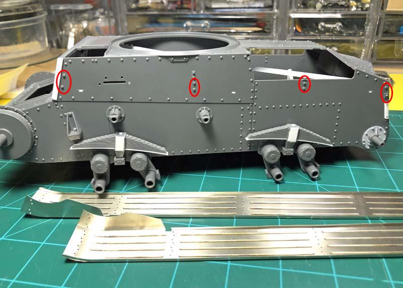

There are a number of molded on bolt heads on the chassis for the kit provided photo-etched fender brackets that need to be removed in order to fit the Aber fenders and brackets. These are shown in the red oval shaped outlines.
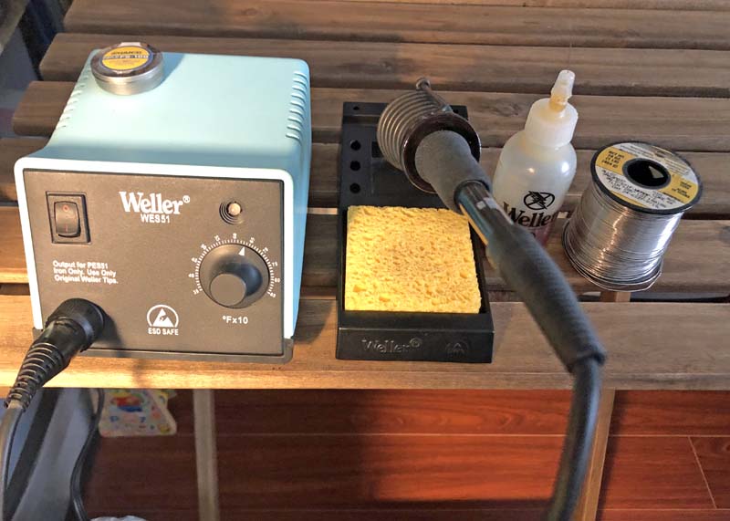
Sometime ago I had purchased a dedicated variable heat controlled soldering iron station designed for using a multitude of shaped and size tips. Deionized water (keeps the solder station sponge from getting black from the solders dross), solder flux designed for using leaded solder, and .010” diameter 60/40 leaded solder. Solder wick also comes in handy for removing solder mistakes or blobs of extra solder. You’ll also need alcohol, acetone and cotton swaps for cleaning off the flux. Alcohol cleans off the flux but leaves water residue on the surface that will oxidize the photo-etch brass so a light pass with acetone will absorb the water and leave the surface very clean, just do your best not to get it on your hands or breathe it in for long periods of time. Always wash your hands after using anything leaded or use a pair of rubberized type of gloves.
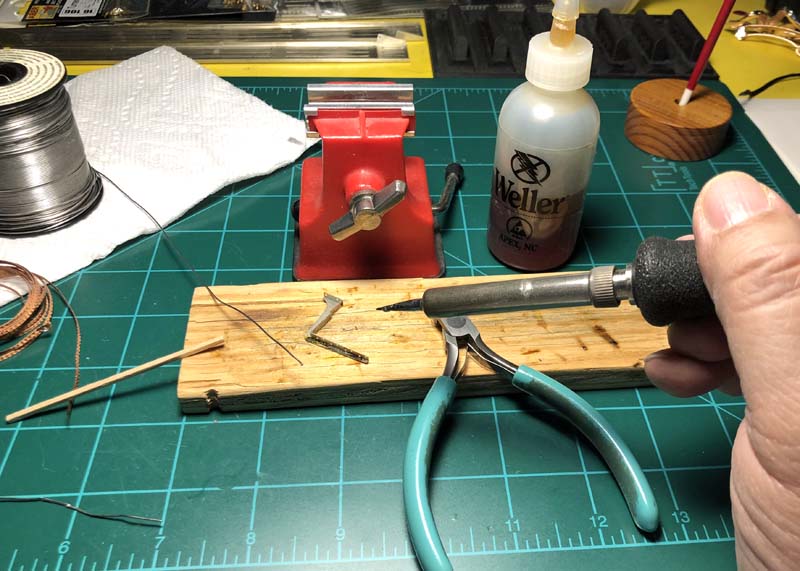
A few more items to gather for soldering is a small flat piece of wood, No. 2 paint brush for applying controlled amounts of flux directly where you need it and sets of different size soldering tips to offset the effects of larger sized area of the photo-etch to act as a heat sink which prevents good solder flow. Heat and flux are your best friends when soldering. A plastic vise with aluminum grips are ideal to use here because they do not absorb as much heat away from the parts being soldered as a full metal vise would. I’ll stop here as soldering deserves its own feature. At some point I plan on doing a feature on the subject of soldering.
As a note, solder is soft and you can easily but carefully slice away excess solder with a sharp rounded edge blade. It can also be sanded with the same grits used for plastic and can be polished with a cotton swap. Solder wick and flux and heated with the solder tip easily removes excess solder too.
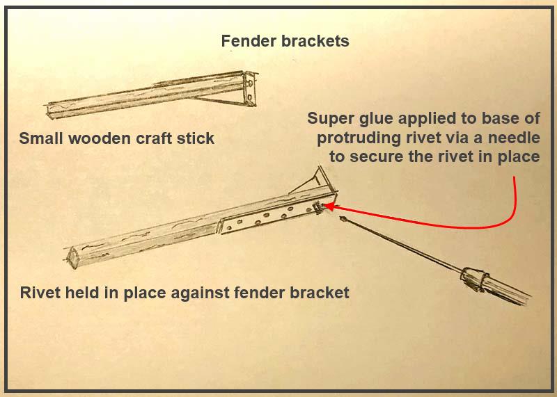
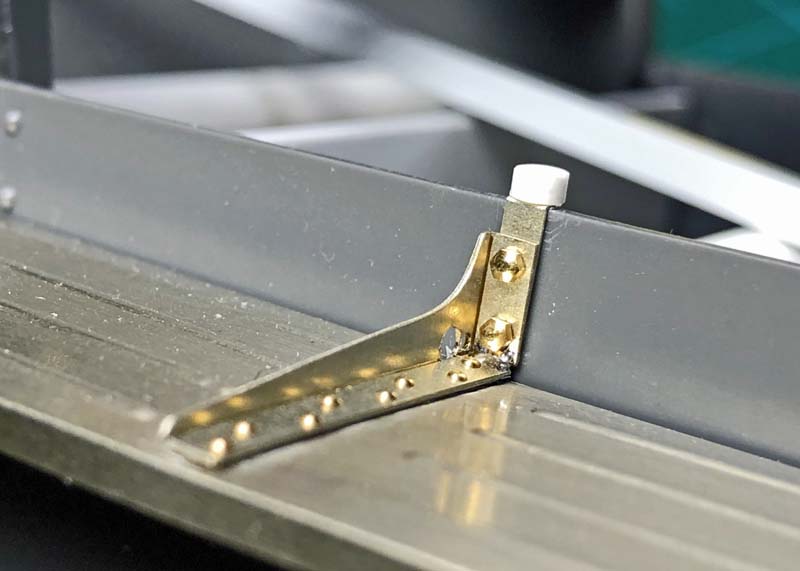
This is the process I used for fixing the small brass turned rivets against the fender brackets. This was done to all of the fender brackets before fixing them to the fenders. Not shown is the process of carefully using a diamond coated flat file to smooth out the ends of the rivets after attaching them to the fender brackets. All of the fender brackets were then fixed to the fenders using the same method of applying super glue to the bottom of the brackets and then applying the brackets to the fenders. The larger front fender brackets where not affixed until the fenders were fixed to the chassis.
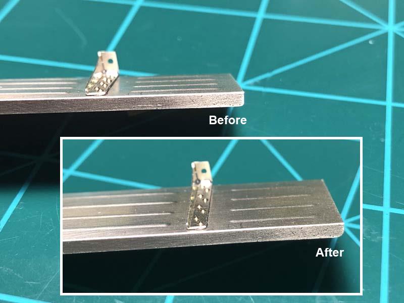
After attaching all but the front fender brackets to the fenders is when I noticed that the curve at the end of the rear section of the fenders did not have a pronounced curve as seen on pics and on the reference material I had on hand so I fixed that issue using a flat diamond coated file.
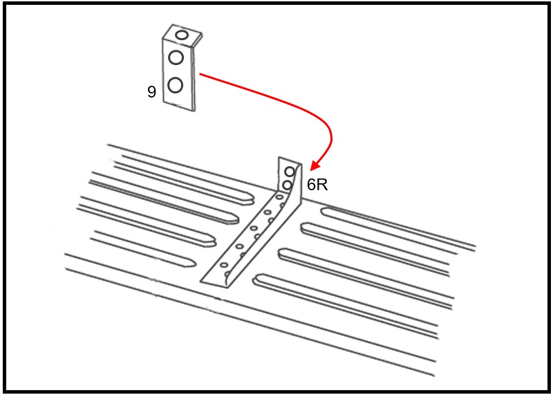
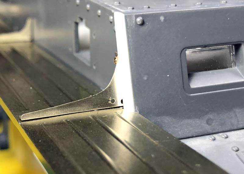
Before proceeding there is something important that needs to be pointed out. The Aber instructions show that part 9, metal strip for the engine door snubs, should be attached to the front of the R6 bracket face? However after affixing both brackets, R6 and L6, to the fenders there is a small gap left between the edge of the fender and bracket about the same thickness as the strip, part 9. I could not find any pictures of that area of the vehicle to verify if the brackets were fitted as per the instructions or to the backside of the brackets?
In the end I chose to place them to the backside of the brackets and this turned out to be correct as it left no gap between the fenders and chassis. The holes in the fenders are offset just enough for placing the fender brackets away from the edge.

I used the fixed brackets on the fenders as a template for drilling holes on the chassis to place the provided bolts that hold the fenders in place. A needle on a pin vise was used to dimple a center for drilling the holes on the chassis. The holes on the brackets and snub strips are larger in diameter than the shanks of the bolts this is good as you only need to be close and not dead on. A .032” (0.8128mm) diameter drill was used to open the holes for the fender bolts. Slow setting gel super glue, applied via a needle to the inside of the drilled holes, was used for fixing all the bolts against the brackets and securing them in place to the chassis.
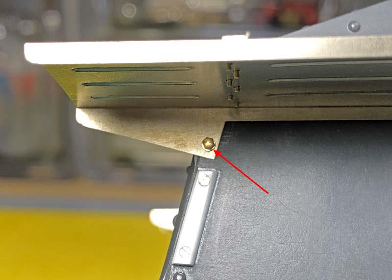
A lock and flat washer are fixed to the underside of the fenders to prevent the bolt from vibrating loose as it sits very close to the tracks. This is one of the areas where extra hardware was needed.

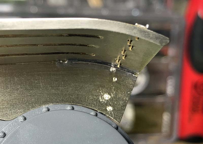
This is the area where I did not use the turned rivets because the holes on the brackets and fenders do not line up. What I did instead was to use 16 of the supplied photo-etch rivet heads. I placed the outside fender rivet heads with the flat backside facing out and on the inside of the fenders I place them front side out.
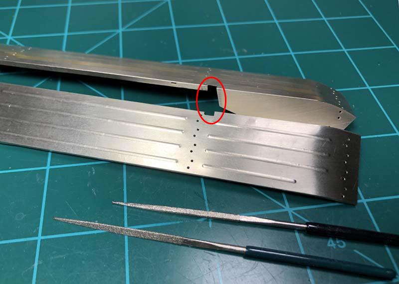
Here you can see the rivets passing through to the underside of the fenders and the cutout for the front superstructure 50mm thick armor plate.
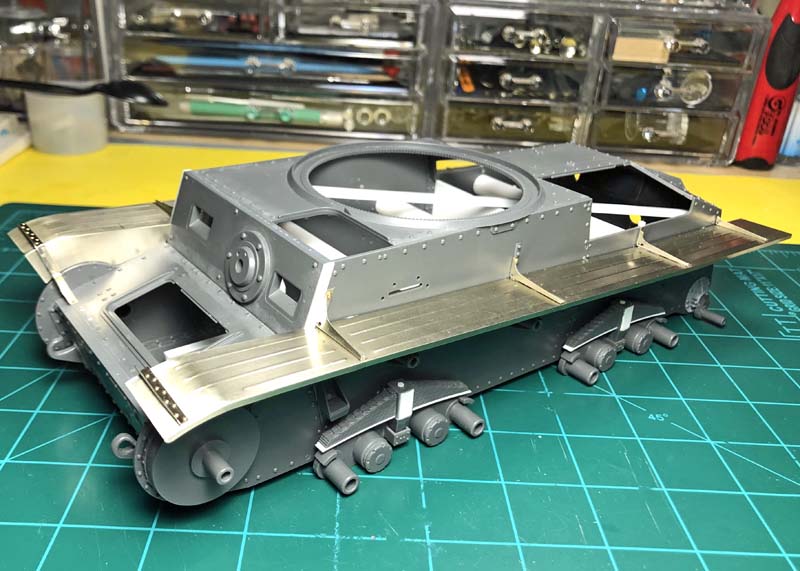
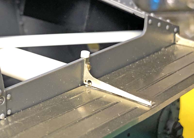
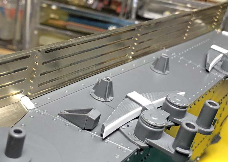
The fenders now installed.
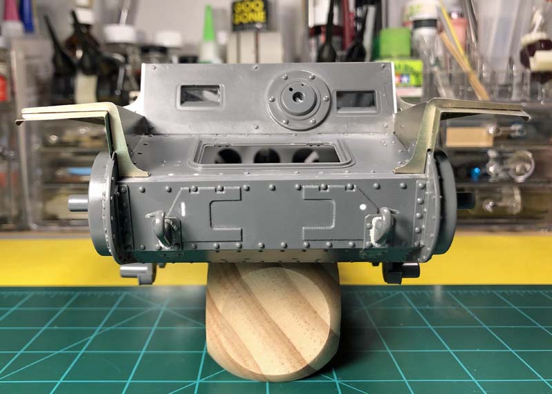
The fenders are angled from the inside to the outside edge as on the real vehicle to allow rain water to run off. I was unsure if Aber had captured this feature because the angled fender brackets appeared to have 90° corners. The angle is very pronounced at the front end of the fenders and lessens toward the rear just as on the real vehicle. I am very happy with how this turned out and hope that for some of you that are hesitant to work with photo-etch will give it a try.
Thank you for dropping by, more on the way . . .
5 Likes
Brilliant informative update. Thank you .
Keith,
Thank you for dropping by I’m glad you’re getting something out of this to use on your builds. Over the years I’ve learned so much from others posting and now it’s my turn to give back. And thanks again for the comments, it’s much appreciated. A lot more coming.
~ Eddy
Eddy,
I havent got my hands on this kit yet but learning a lot of new things all the time, some so obvious you wonder how you didnt think of it yourself LOL
Keith,
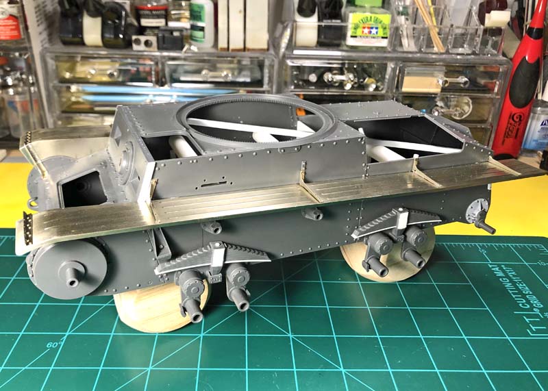
In my opinion this is a very good kit with plenty of detail and options right out of the box. I picked up this kit via evilBay for a reasonable price back when it was first released. I’ve seen this kit built up here on Armorama and elsewhere on the net and have not heard anyone make any complaints about warpage so this must be an exception on my example. Aside from the floor pan (A3), being warped I found that the right side superstructure panel (B2), also suffered from slight warpage across its length. This issue became apparent after fitting the track guard against the panel.

I was able to solve this problem by installing lengths of styrene tubes to the inside of the hull to help eliminate the gaps between the track guard and superstructure panel. Each tube was cut and carefully sanded to length so as not to cause an issue with the opposite superstructure panel. I had forgotten to mention this on my last update. I noticed this issue as I am now getting ready to close up the openings over the engine, transmission and crew areas.
Happy hunting and finding your kit I believe this kit is still readily available.
~ Eddy
2 Likes
Very impressive Eddy.
Thanks for sharing all your experience with PE, namely the tools and techniques.
Thank you for stopping by and thanks for the comments it is much appreciated. I will be getting into more on the photo etch after this next small update. I do hope I am being of some help to you and others that may be contemplating the use of photo-etch on your kits.
~ Eddy
A small update on the armored transmission cover hatch and left and right engine cover hatches.
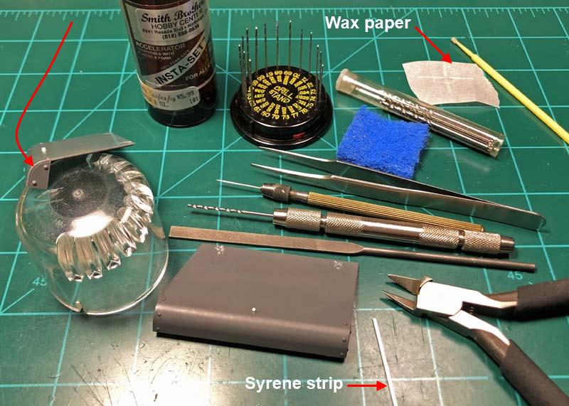
Here are all of the tools used to rework and assemble the hatches. I made note of the wax paper as here is where I place a small amount of super glue. The wax paper is moisture and grease free so the super glue will not set up while sitting on top of this medium and will usually last in its liquid state for one modeling session.
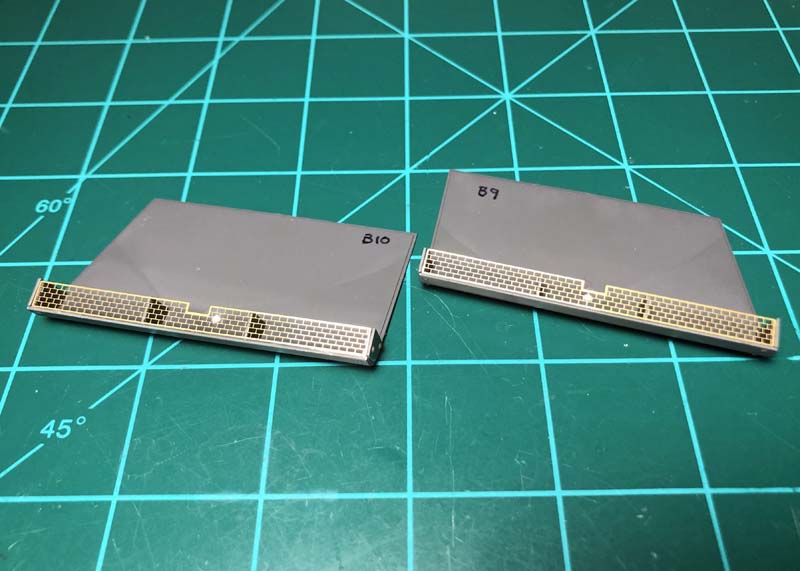
The kit gives you the option of two different armored engine hatch sets. The set (Parts B9 & B10) with a reduced number of rivets along the horizontal length of the overhang are intended for use if you’re modeling the Ausf. F. These are also the same as used for the Ausf. G.
All of the molded on hinges have already been removed from the hatches and the areas filed and sanded smooth using 220 and 400 grit sand paper. I follow that up with blue scotch bright, leaving the plastic smooth and shiny ready for paint. It’s hard not to sustain some surface damage but if you’re careful removing the molded on hinges the little damage incurred will be hidden under the photo-etched replacements. The vertical armor plates on the sides where then added. I found I needed to sand the thickness down on some of the plates to keep them from protruding away from the edge of the hatch covers. Also note that there should be a very thin gap between the hatch and plate as on the real vehicle.
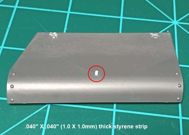
The engine hatch covers come with a recessed latch key; this is not a problem as there were some vehicles that are seen with this type of arrangement. But most photographs show a protruding hatch key so I drilled out the key using a needle chucked in a pin vise to create a center dimple on the existing key and step drilled that out to a final hole size using a .059" (1.4986mm) Dia. Drill. This left the hole a bit larger than the square styrene strip used for the latch key. This allowed me the advantage of adjusting the square strip on the hatch. On the real vehicle the key is a four sided square with a convex shaped top. On the kit this is represented as a round nob in a recessed hole. I shaped the styrene strip top to match this feature and then cut it just long enough to hold it with my fingers while the super glue set up. The super glue filled the open sides between the square styrene strip and round hole. I allowed only enough glue to secure the styrene strip and not enter the counter sunk hole.
Here the protective metal screens below the overhang on both armored engine hatches have been secured with super glue.
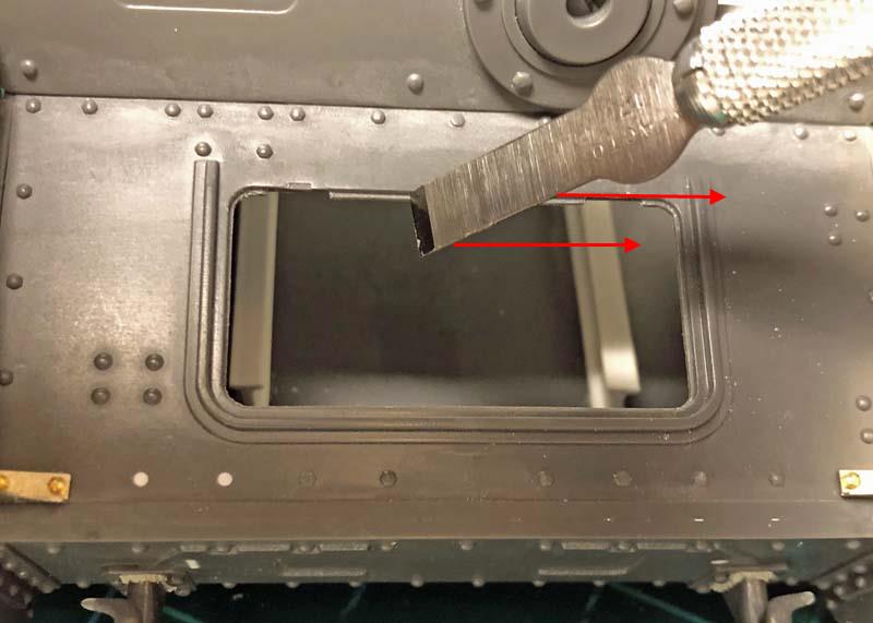
When test fitting the transmission hatch onto the glacis plate opening I found that the cover sat proud of the plate and the radius corners did not match up to the radius corners on the glacis plate opening causing interference with the hatch and glacis plate. To remedy this issue a flat file was used to remove material from the hatch radius corners to match those on the glacis plate. Then I ran a chisel blade to score material away from the ledge of the opening on the glacis plate in order to allow the hatch to sit flush with the glacis plate. This is shown in the photograph with the chiseled end facing away from the direction used to scrap material off the surface of the ledge. The same method was used to sit the engine hatches and metal screens flush with the surrounding plates.
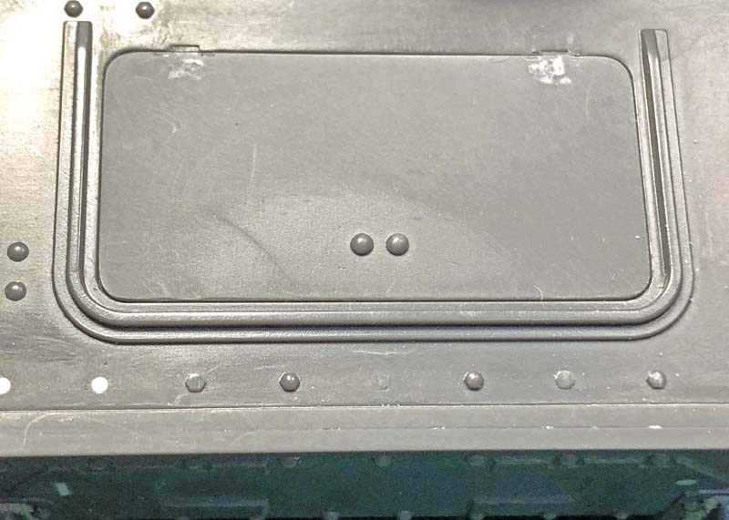
Here the transmission hatch cover now sitting flush with the glacis plate.
Thank all of you for dropping by it’s much appreciated. Until next time enjoy and happy modeling.
~ Eddy
3 Likes
Sorry about the long delay between updates but I’m not getting the time to model that I would like to have. Thanks for your patience and understanding that is very much appreciated by me.
Since my last update I noticed that I had forgotten to mention about the engine hatch snubbers. I don’t have any reference pictures of these items so I’m guessing as to how these parts looked and how they may have been installed. The molded-on snubbers on the kit parts are perhaps a good representation of what the real snubbers may have looked and the Aber instructions will have you stack three (#8) photo-etch rings together to replicate and replace the kit snubbers. I decided to scratch make my own hopefully I’m not too far off the mark.
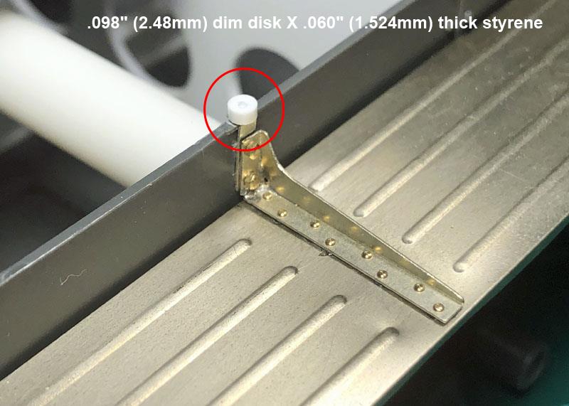
Here is what I came up with for the snubbers. I also drilled out a center hole to represent where a bolt would have been used to secure the snubber. I didn’t place a photo-etch screw inside as you would not be seeing this once the engine hatch covers are fitted over them. A .0292” dia. (0.74168mm) micro #69 drill was used for creating the center hole.
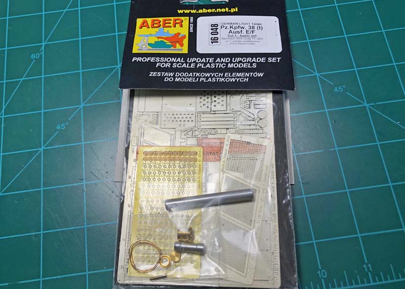
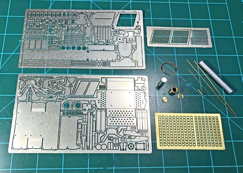
I will be using Aber’s #16 048 Vol 1 Basic Set for replacing or adding many of the items to this kit. Voyager Model has a similar photo-etch set available for this kit too. These are Voyager Models #16028 Basic Set and #16029 fender set. Both of these sets are also designed for this kit should you wish to go that way. The Aber set comes with four frets of brass in differing thickness, various rod diameters, a few machine-made items (for use on the turret), an aluminum rod for helping create the curved sides of the smoke canister box and a piece of copper wire. A two-sheet line drawing instructions are also included (not shown). The instructions can be downloaded or viewed from their site. Also not shown are a set of Aber #16 100 turned hexagonal bolts that come 30 pcs. to a package. These bolts are almost the same as come packaged in the fender set with the exception that the shafts are a just a bit shorter.
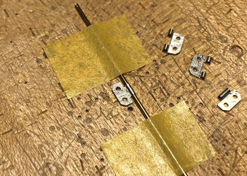
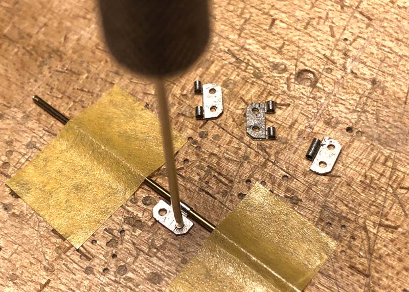
Here I’ll be building the hinges for the transmission cover. Following Aber’s instructions, I secured the required brass rod with tape offset onto one of the hinges ends and then folded the other hinge end over the rod. The idea is to have both hinge ends align and match up together forming one hinge end.
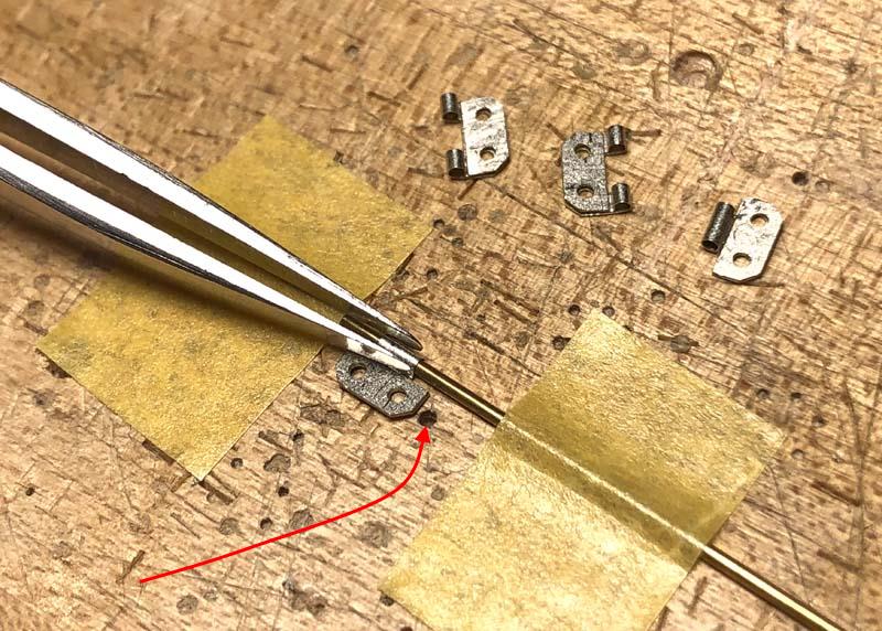
Using a flat ended set of tweezers helps to form the hinge tightly against the rod but not tight enough to keep the hinge from rotating against the rod. The flat ended tweezers also help in tucking the hinge around the rod and aligning the hinge ends together. Here I’ve used a hole in the wood block to align the hinge ends once both hinge ends come together. Simply slide the hinge over the hole.
After sliding the hinge over the hole, I run a secured needle in a pin vise into the hole to align the upper and lower holes on the hinge ends together. Wiggling the needle around the holes assures that the holes are aligned with each other. The hole size on the wooden block should be large enough in diameter to keep the needle from sticking to it and deep enough that the end of the needle doesn’t touch the bottom.
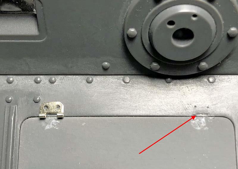
I noticed a small notch on the glacis plate after removing each of the molded-on hinges. I used these notches as an alignment guide for placing the new hinges on the glacis plate. After placing the hinges in their proper locations, I used the same needle in the pin vise to dimple the glacis plate for drilling holes to fit the turned hexagonal brass bolts to secure the hinges.
Here again as on the fenders a .032” (0.8128mm) diameter drill was used to open the holes for the hexagonal hinge bolts. These bolts were also secured using a slow setting gel super glue. The glue was run into the holes using a needle secured to a pin vise.
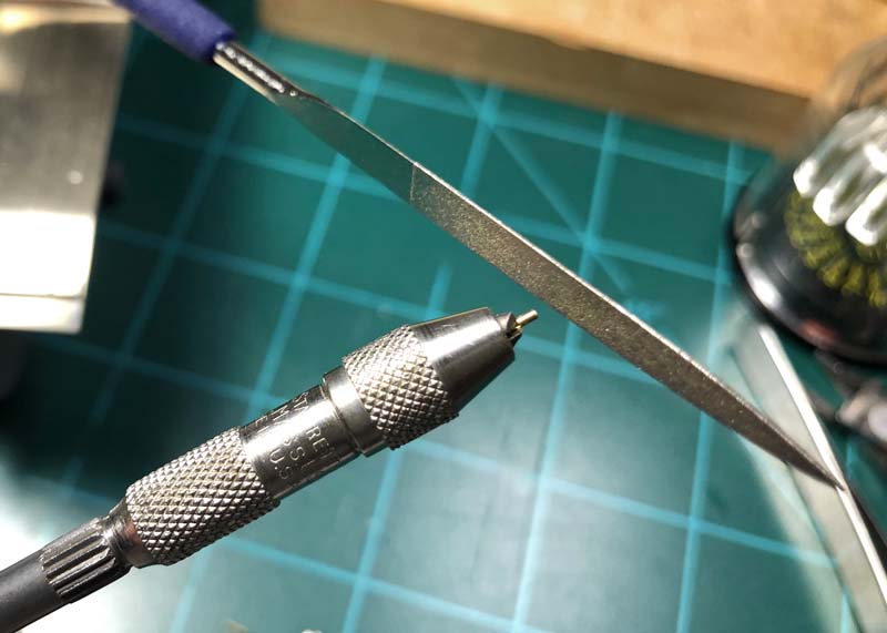
Two brass hinge pins were cut to fit the length of the hinges using the recommended diameter rod per the Aber instructions. The ends were smoothed over using a diamond faced file and a slight tapper was added to aid installation.
The second hinge plates were then added and a small amount of super glue was applied to the outside of the hinge pin and slide back in place to secure it to the hinge. The completed assemble was used to dimple the transmission cover for drilling the remainder of the holes for the hexagonal hinge bolts.
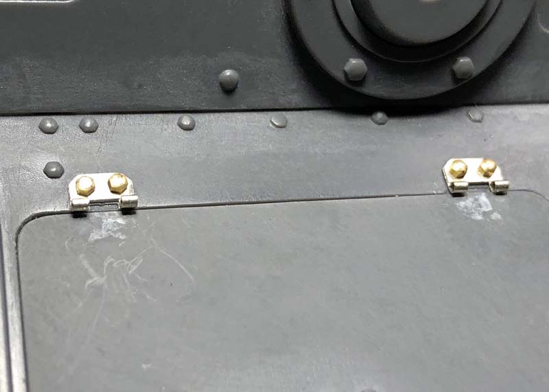
The completed hinge assemblies.
The working transmission hatch cover.
Again, thank you for dropping by and checking out my build, I do appreciate it!
~ Eddy
5 Likes
Wow! That is really beautiful work. Thank you for sharing.
—mike
Awesome work as always. On the snubbers I guess they are like the rubber door stops held by a screw/bolt through the middle just as you show them. Works for me.
Thank you for your sincerely nice comment, it’s appreciated. More coming as time permits . . .
~ Eddy
Keith, I’m guessing the idea was to keep things as simple yet workable as possible when the engineers designed this vehicle.
~ Eddy
I’m back with another update, thank you for being patient and for dropping by, it is very much appreciated. Things have been a bit busy for me lately and I just have not gotten that much bench time but I do manage as best I can so apologies for the delays in me posting.
This update concerns the installation of the engine bay armored hatches using the photo-etch hinges.
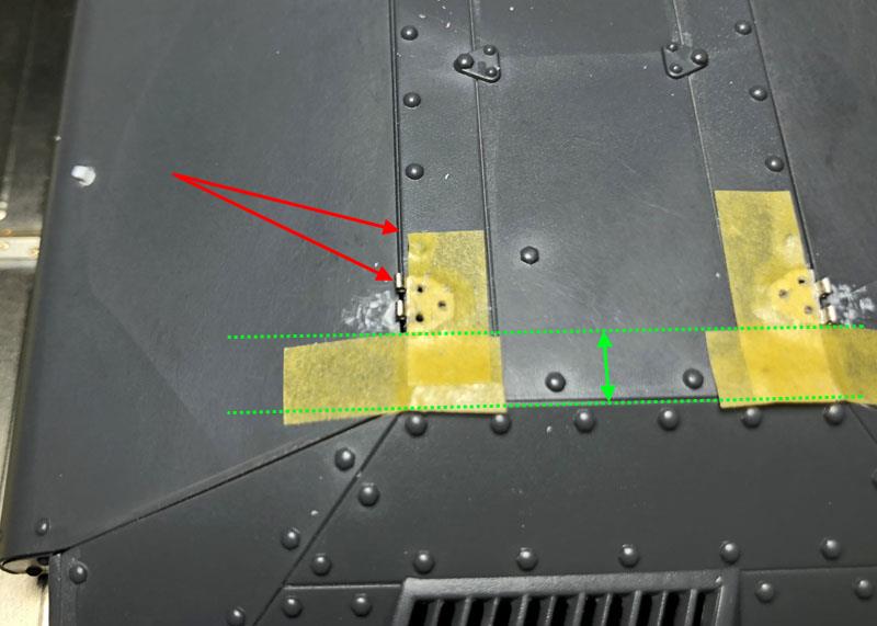
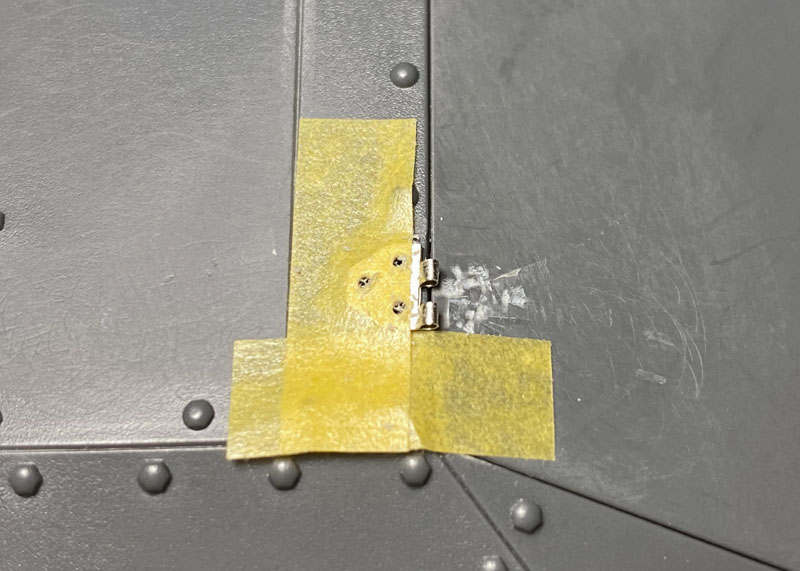
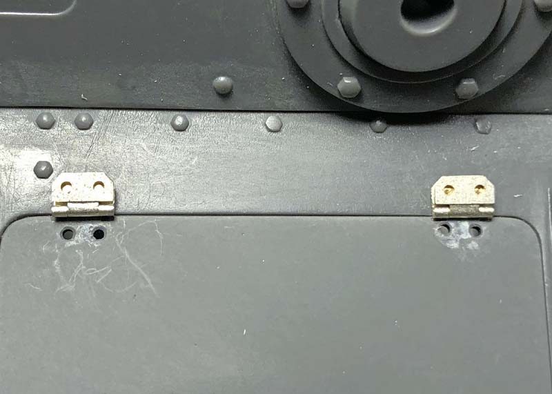
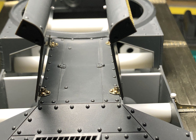
One of the first things to do is to place the engine bay hatches on there respective places and check to see that the hatches do not sit proud of the surrounding plates or bind against the sides keeping the hatches from sitting flush. After folding all four of the hinges for the engine deck center support plate I aligned and centered each of them over the openings using Tamiya low tack tape. There are areas left open on the hatch ledge supports where the engine hatches sit that help in determining where the hinges should sit. This is pointed out on another photo below. Just make sure to keep the hinge pin supports aligned and centered over the space between the engine deck center support plate and hatches as pointed out with the red arrows.
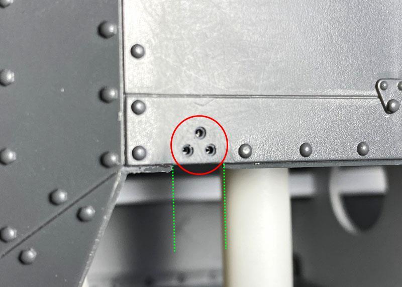
Here you can see the separation on the engine hatch support ledge where I used to center each of the hinges on the engine deck center support plate pointed out with the spaced green lines. Using the hinges as templates I drilled the three holes through the engine deck center support plate and counter bored the top edges to provide a relief area for the super glue to keep it from oozing out from under the hinges.
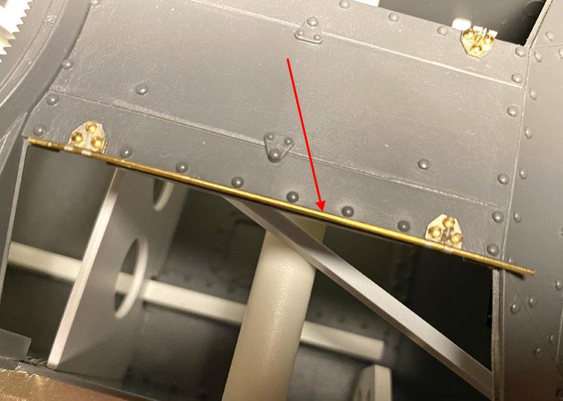
A length of the same diameter wire for the hinge pins was used to align the two hinges as shown on each side of the engine deck center support plate.
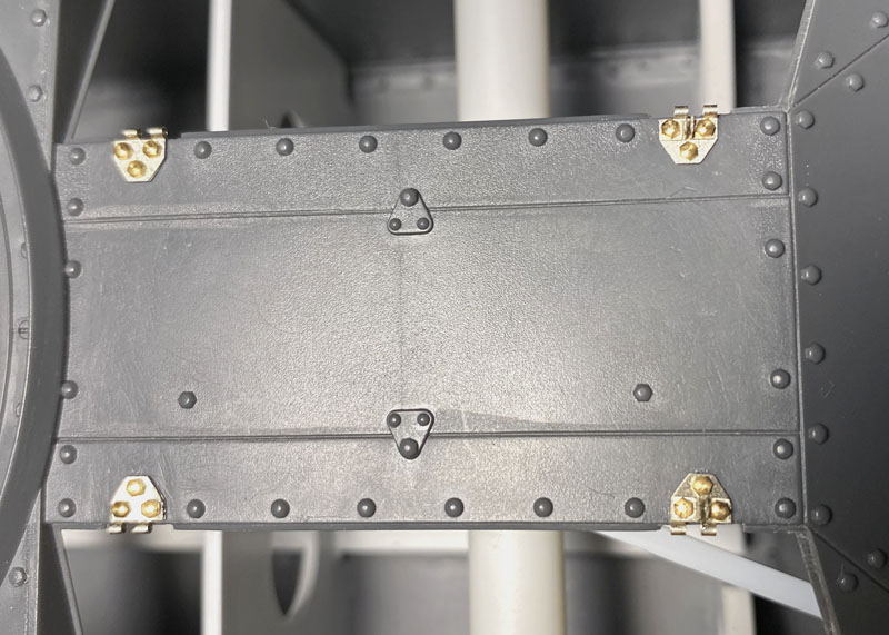
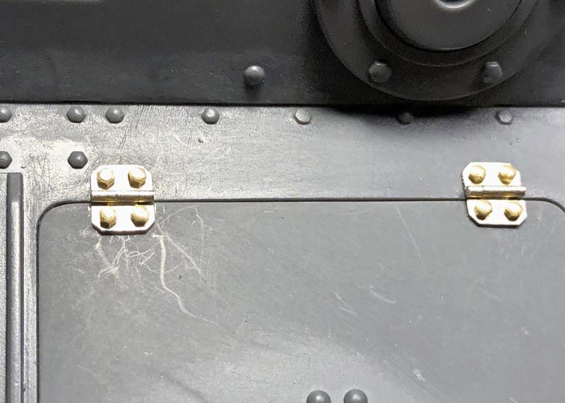
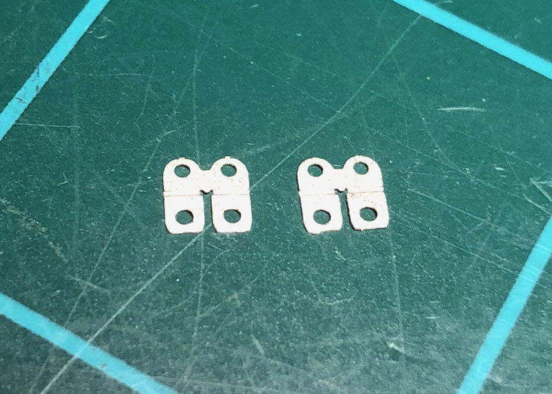
Here all four hinges are now installed on the engine deck center support plate with their bolts along with the female hatch hold braces on the rearmost hinges.
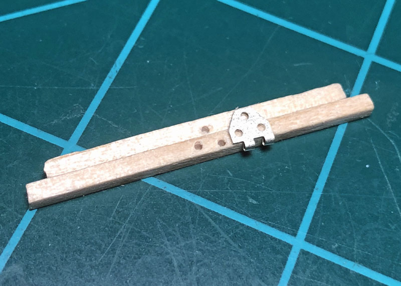
I glued together two pieces of square hobby sticks for making a fixture to hold the three pieces of wire that needed to be soldered to the hinges. Two of the hinges would also need a male hatch hold added to the hinge. These hinges came with some blind holes if you’re building them with super glue, but I needed to drill through them for soldering the wires. I also drilled through the blind holes on the male hatch hold brackets.
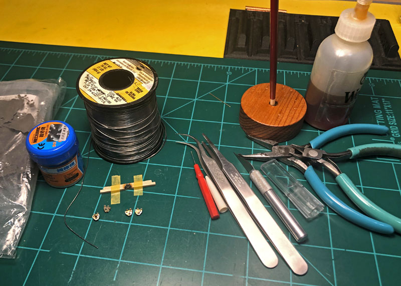
Here is a picture of all of the tools and items used for this process. Not pictured is the soldering station. I used solder paste between the hinges and hatch hold brackets.
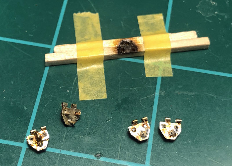
The wires and hatch hold brackets now soldered and semi trimmed. I later placed the soldered assemblies in acetone to clean and remove the solder flux. The wires were then final trimmed flush with a flat cutter and smoothed over with a diamond flat file.
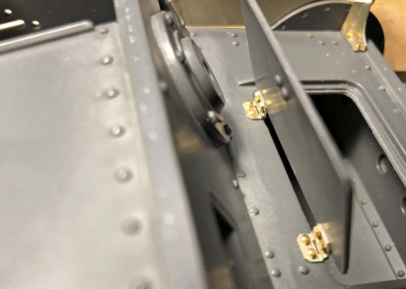
The hinge assemblies now installed on the engine hatch covers and mated up with the hinges on the engine deck center support plate using the Aber instructions suggested wire diameter size as before for making the pins. Hatches shown in the open position.
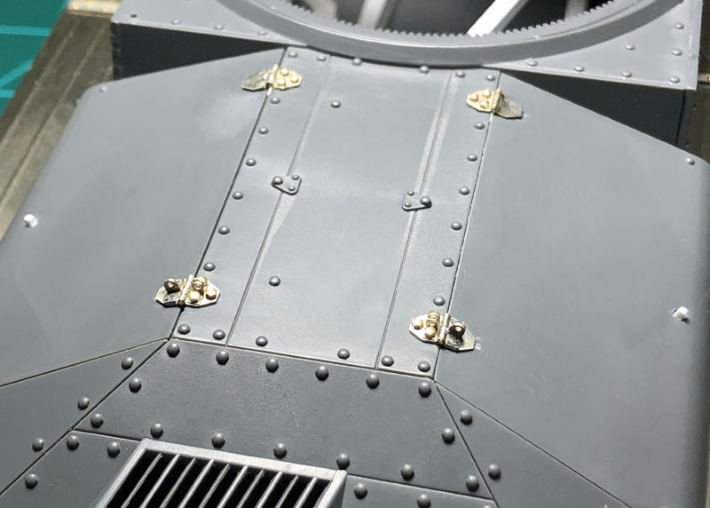
The completed hinge assemblies in the closed position. The engine hatches are fully workable but no engine to display. For me it was worth the added effort as practice makes perfect and this adds to your modeling skills on future projects.
Again, thanks for stopping by it is much appreciated. This was rather complex for me but in the end, it wasn’t as difficult as I had anticipated this was going to be. On to the next tasks, seeing you back in a bit.
~ Eddy
6 Likes
Good to see you have time back on the bench. Inspiring post as always.
Cheers Keith
Thank you Kornbeef,
Just when you think you’re going to get more bench time things happen to keep that from happening! Thank you for your comment it is as always very appriciated.
~ Eddy