Happy New Year folks! It’s January 1 here in the land of the lost, what better date to start a big new build?
I was originally going to post this build in my C1 Corvette project thread, but I really think this deserves a dedicated build log. I picked this kit up back in May and have been itching to get started on it ever since. With my 1/24 '57 Corvette moving along nicely, this is the right time to jump in.
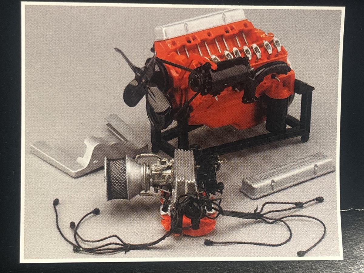
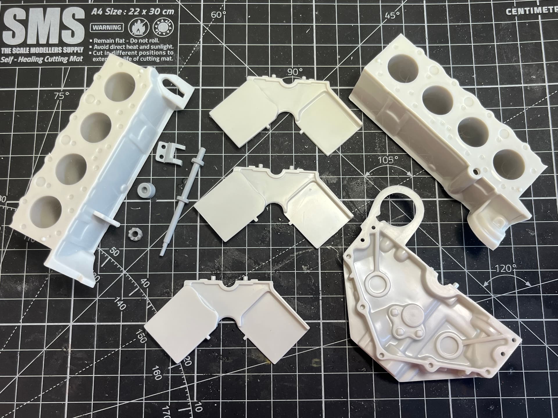
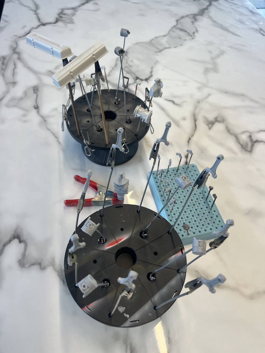
I need to clean up and test fit these parts and make sure I follow the instructions closely because everything is connected and all of the internals move. Some of the parts need to be primed and painted different colours (internal vs external) along the way so the assembly process will take some focus, but I’m really excited to get moving on this one and it will make a great addition to the Corvette project display.
As always, please don’t hesitate to jump in with any comments, advice, critique, or just informative discussion.
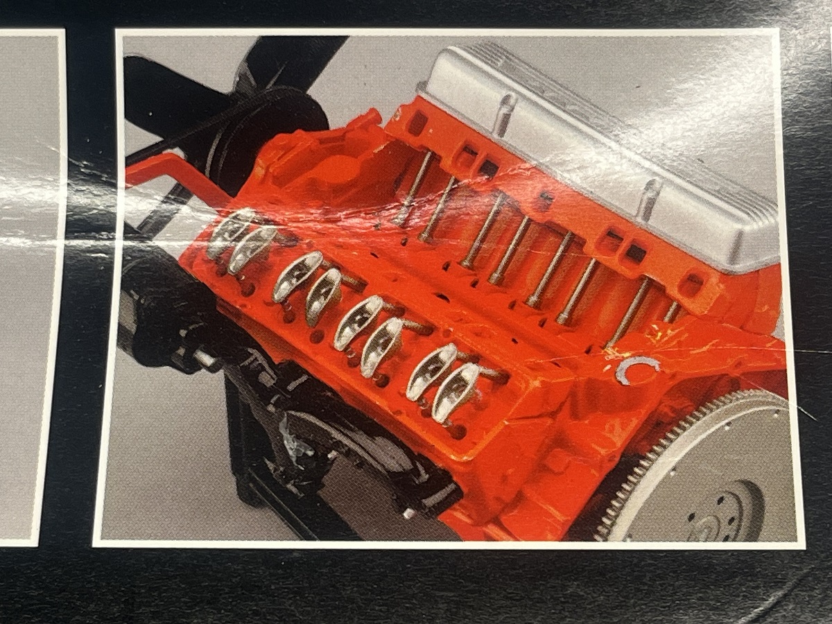
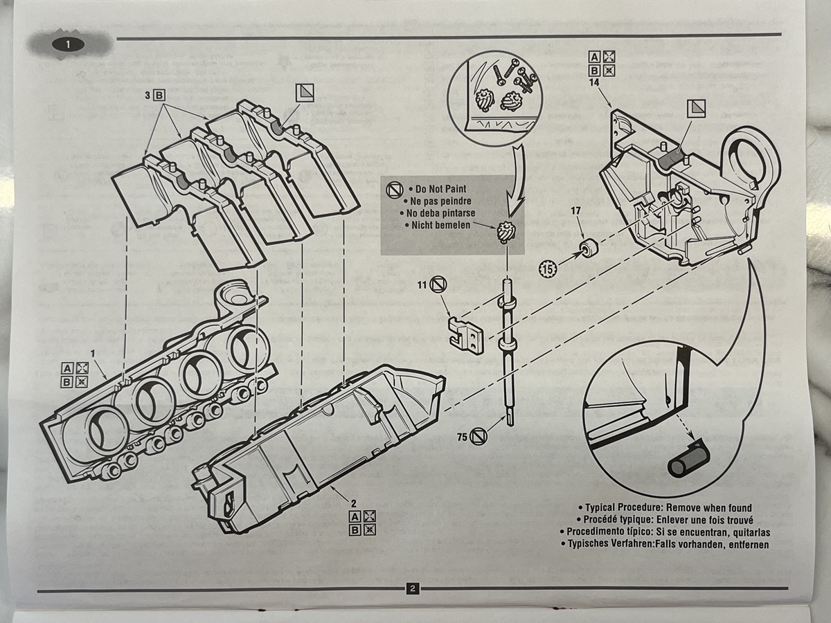
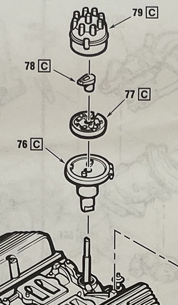
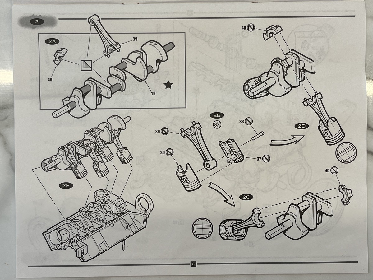
Wow - moving internals . I see on the instructions what appears to be the distributor drive . Does the distributor have internals? Operating valve train?
Impressive!
Happy New Year- Richard
Yessir, everything opens and shuts and spins! I’m planning to get some small disc magnets to hold a few of the covers on but still be able to remove them (rocker covers, oil pan, etc.).
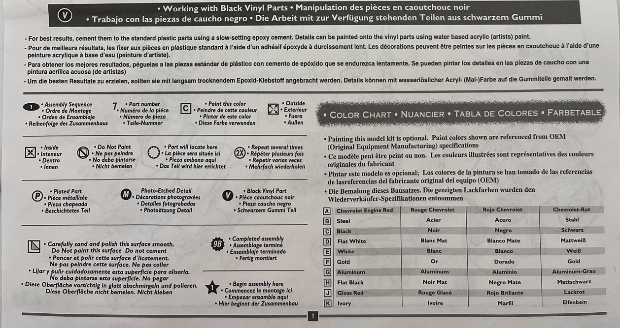
There are lots of warnings about not painting some parts, presumably because of tolerances, but being an AMT/ERTL kit from 1998 I think that might be wishful thinking on their behalf
The kit was also released in 1999 with clear main parts so you can see the internals moving.
Well we have lift-off, and me being me I started at the end
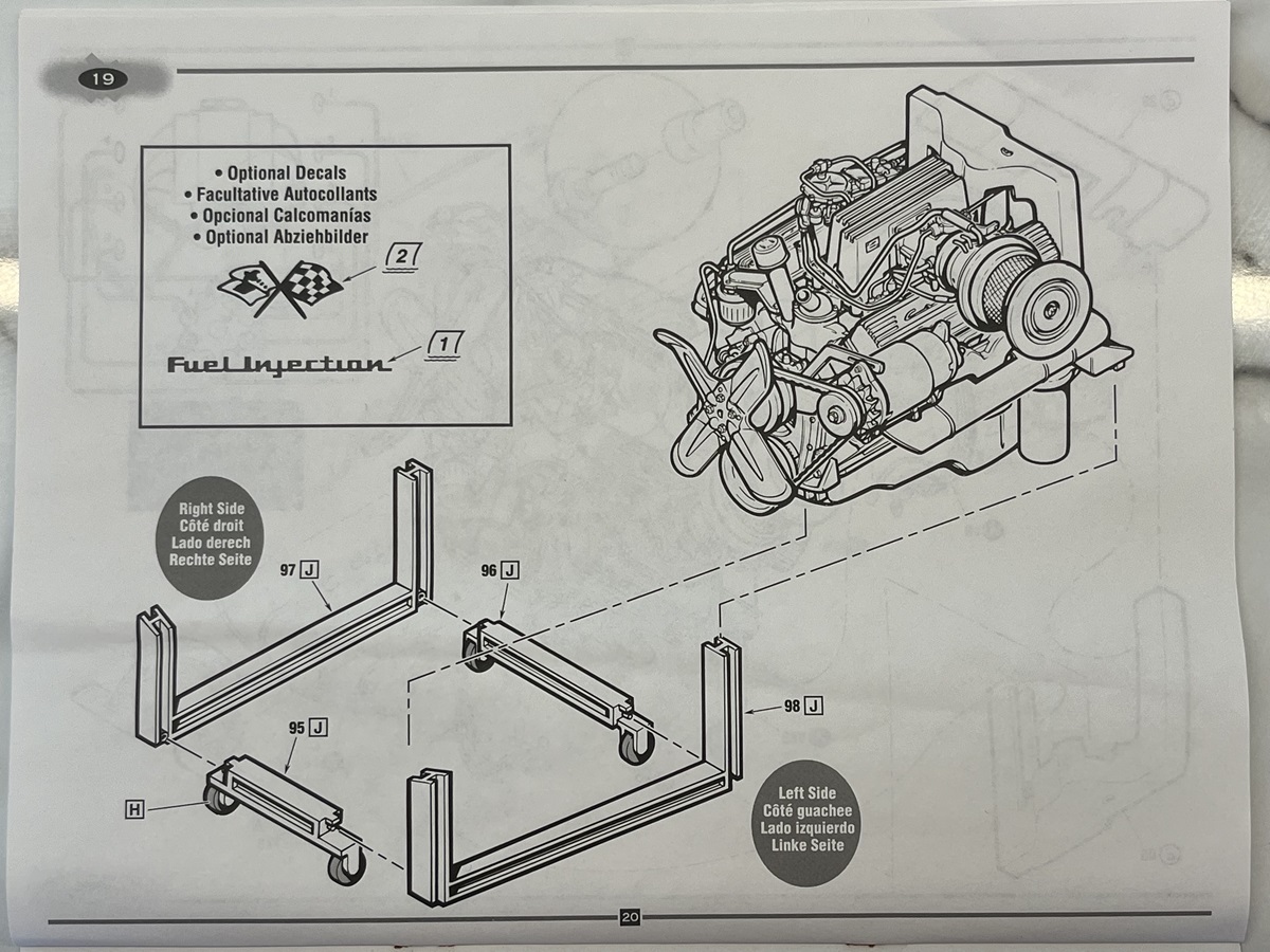
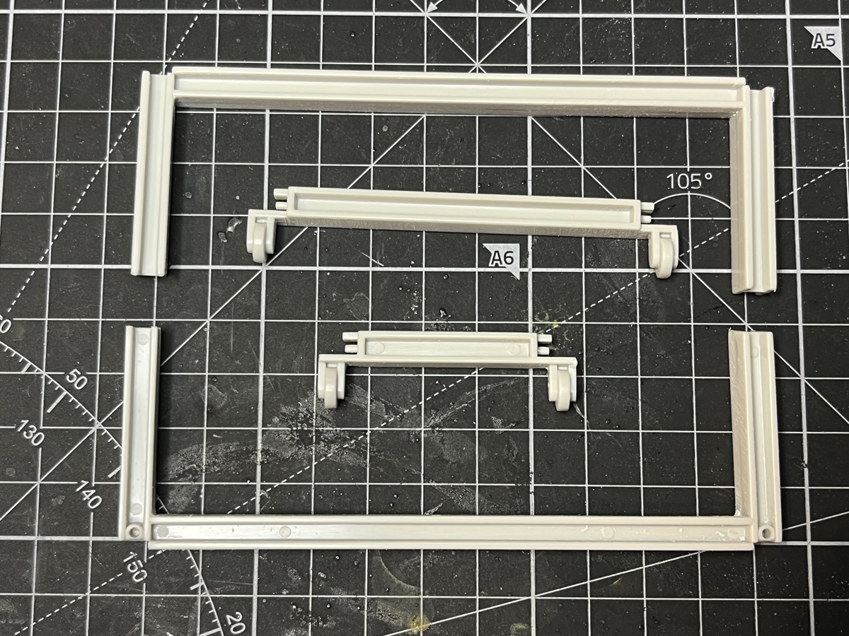
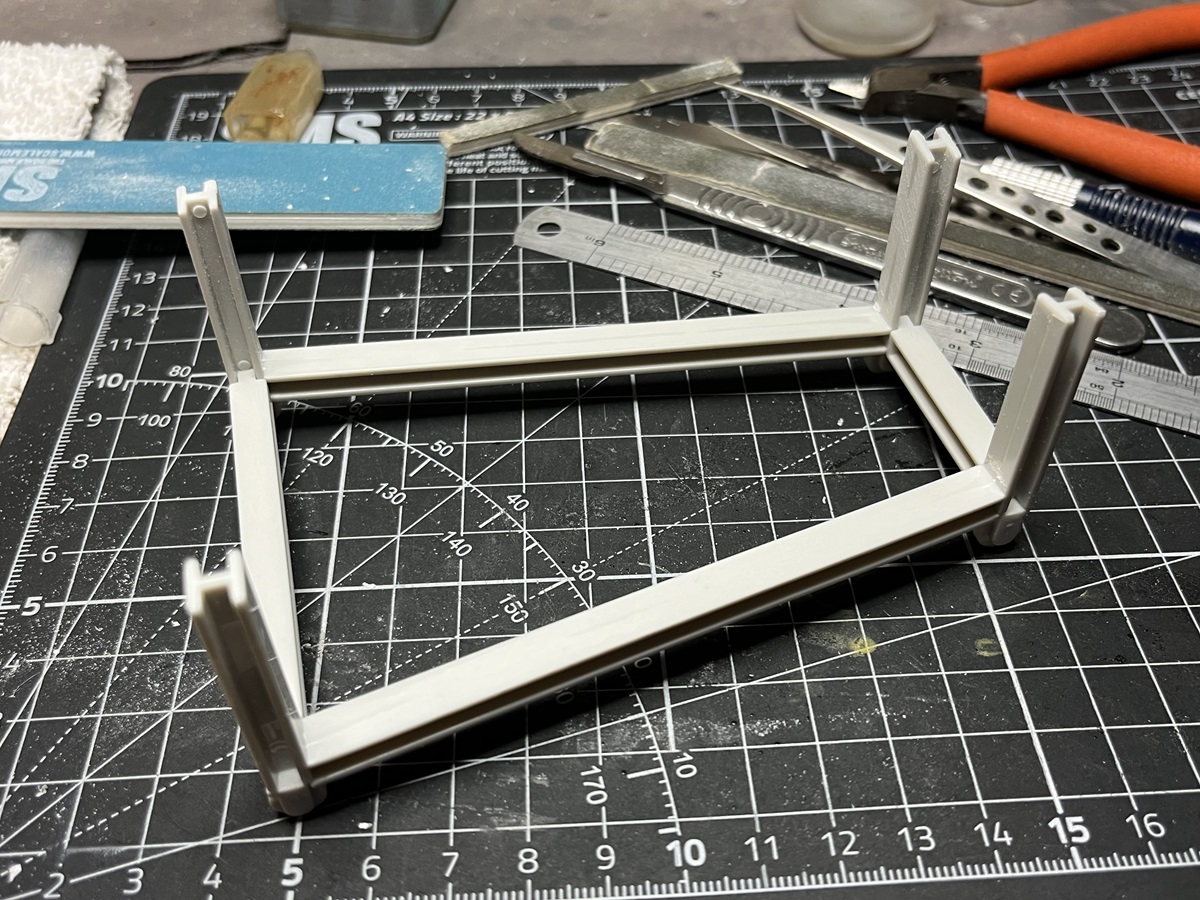
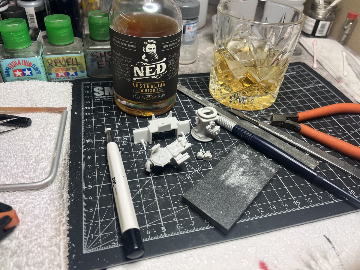
Step 19 is the final step, the engine stand, and also the simplest step with only 4 parts. I wanted to see how the styrene behaved and reacted to a couple of different cements so that was the best place to start. At the end.
I used a different cement on each corner, Tamiya Extra-Thin, SMS Extra-Thin, Revell Contacta and Deluxe Plastic Magic. All performed perfectly so no concerns there.
There was some mould misalignment with clean-up required on every part but nothing major. Just happy to make a start here. This will be gloss black so it doesn’t detract from the engine.
I found a couple of reviews online for this kit and the reviewers were very critical of fit and found it difficult to get the internals working.
Hi D, this will be interesting to follow. As for the internal paints, I wonder if using some of the paints we have available now, like Vallejo Metal Color or Alclad Metal (though I have read these are somewhat fragile), you might avoid the problem?
Anyway looking forward to seeing how this comes together
I’m going lacquers all the way mate, very comfortable using them. I’ve found Alclad very fragile and had no experience spraying Vallejo but heard it can be a nightmare.
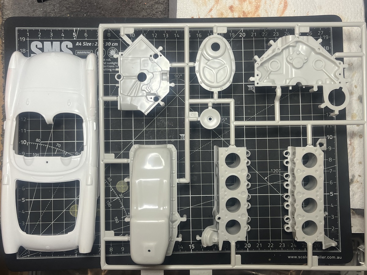
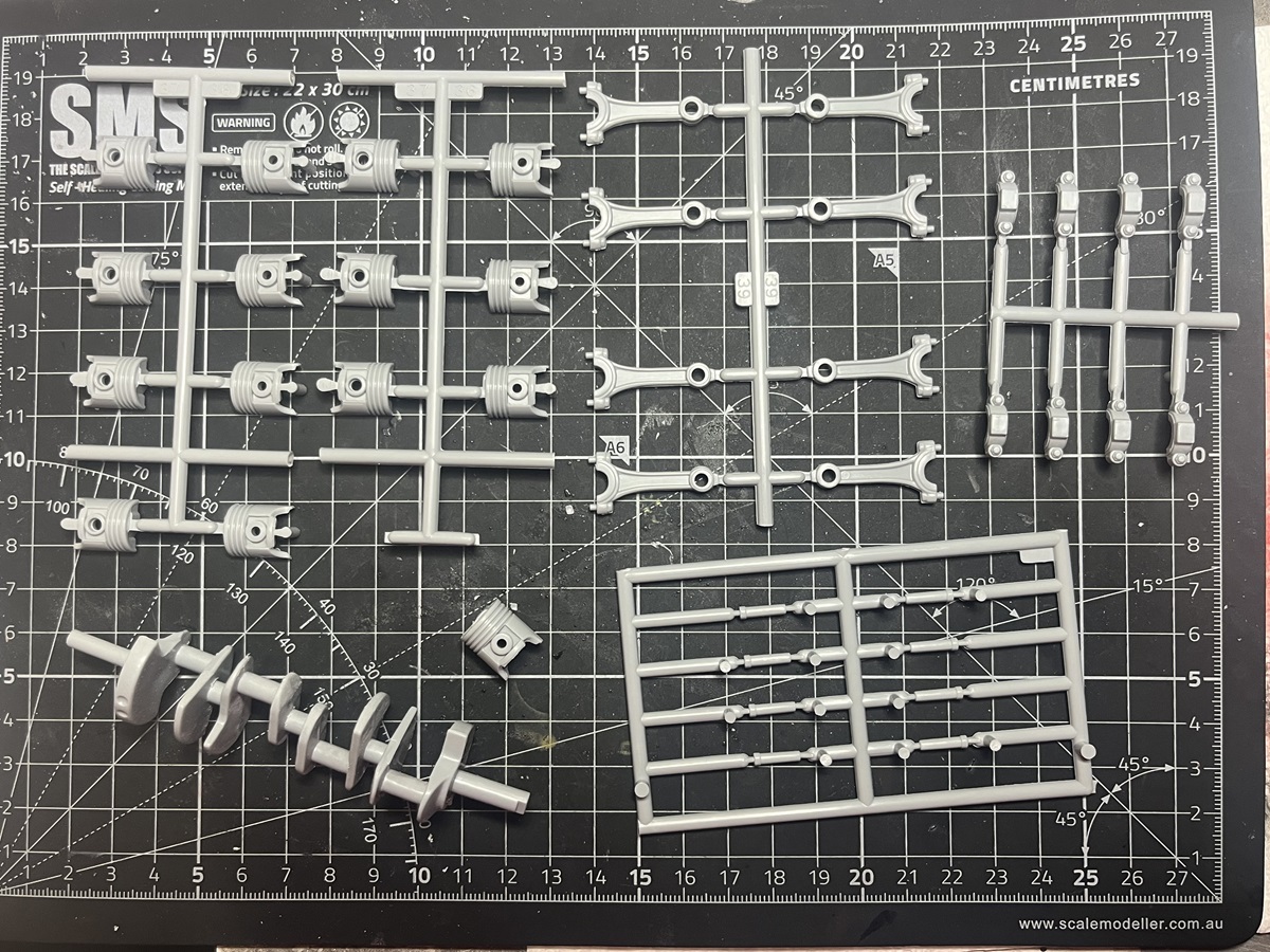
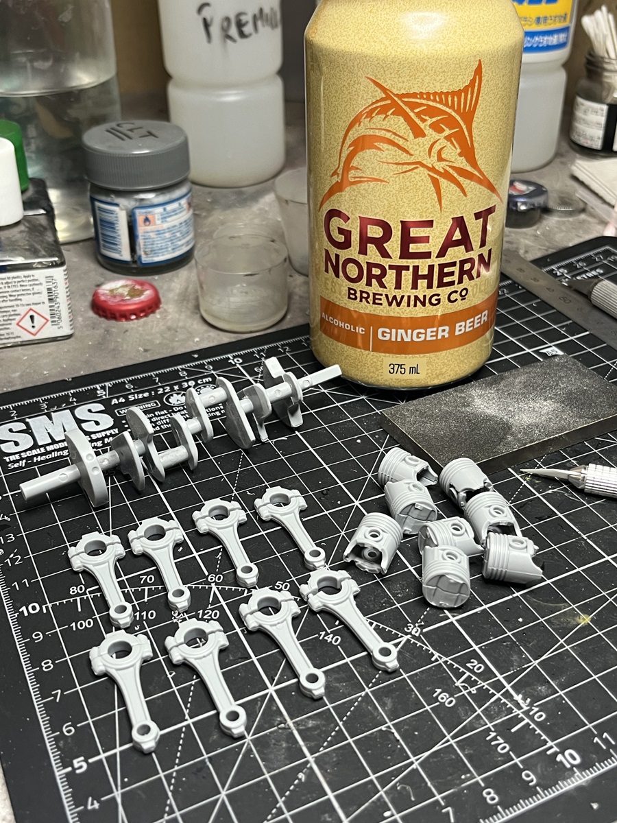
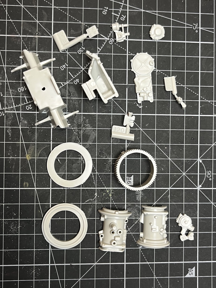
With every step in this build looking like a mini-kit in its own right, I decided to get my OCD on and work my way through the instructions and the sprues and get all of the parts sorted and bagged up in order. This will save time as I move through. I didn’t touch the chrome sprue or the Vinyl or PE parts yet, they can stay safely sealed up until required.
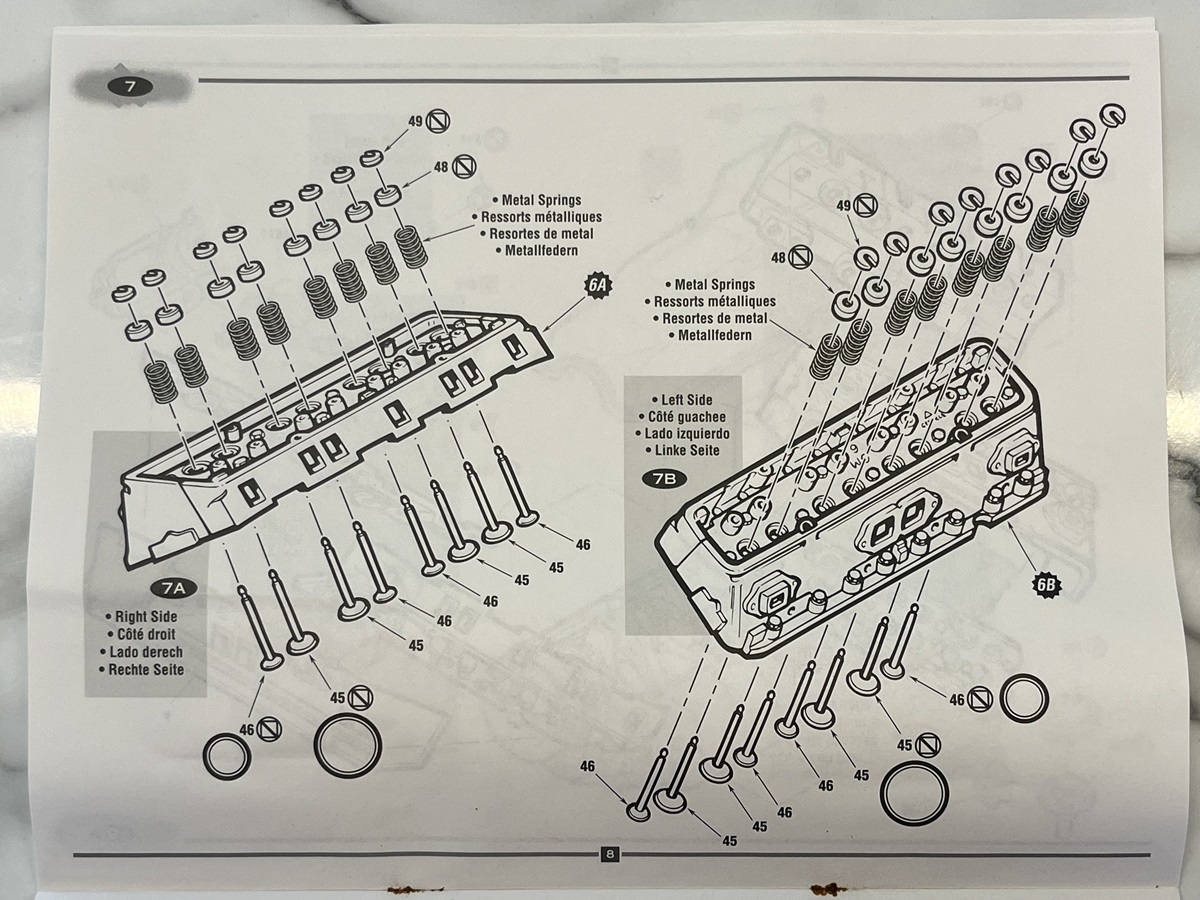
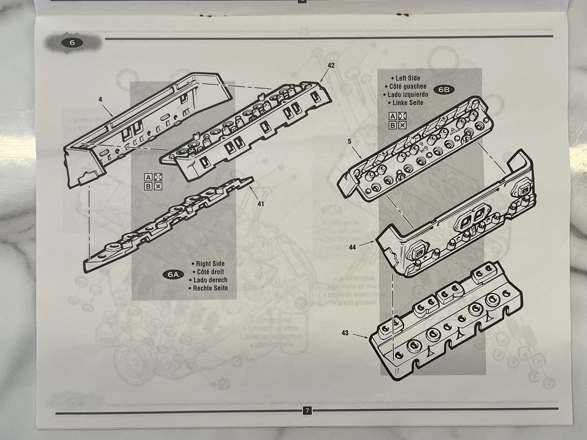
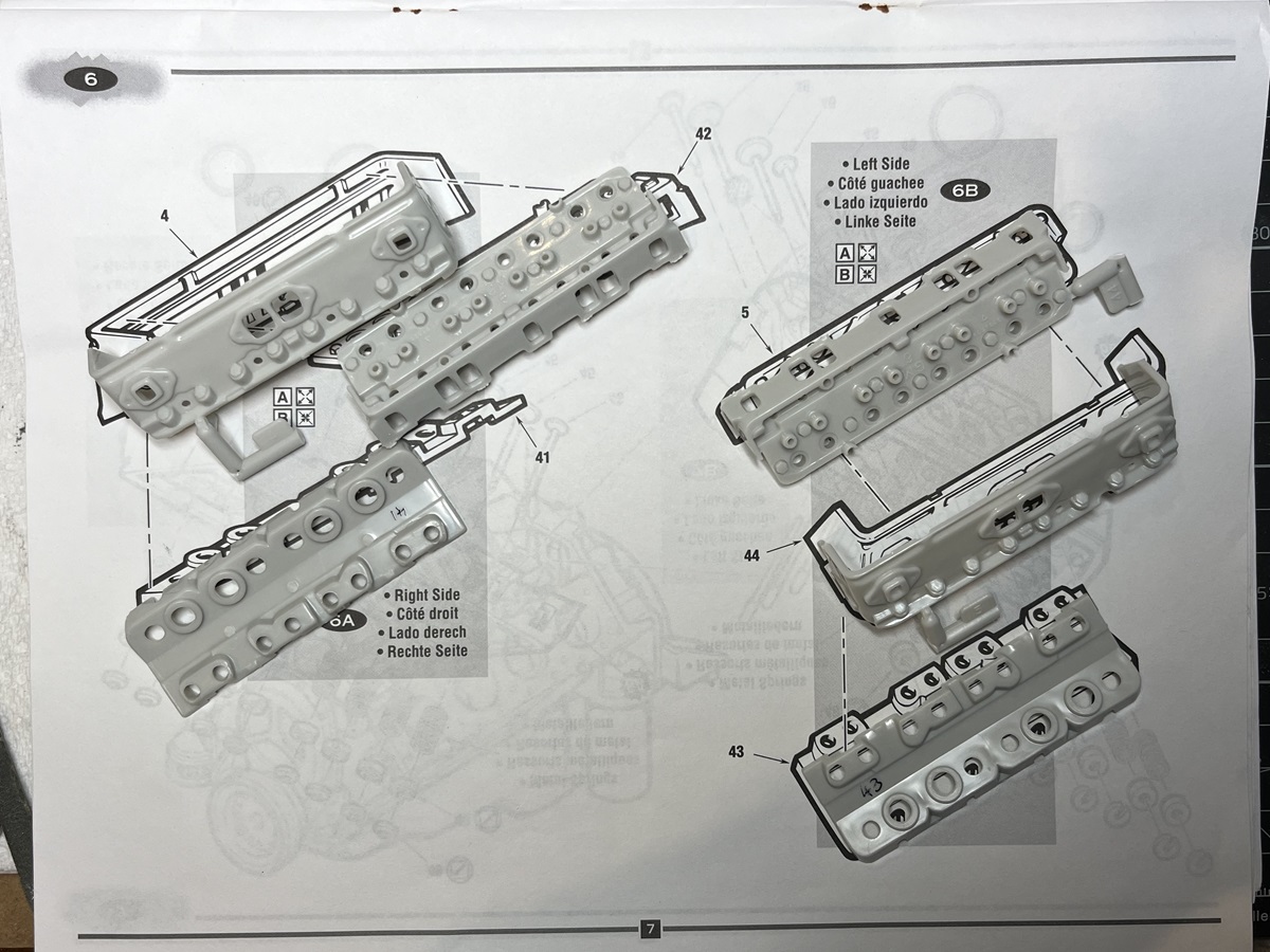
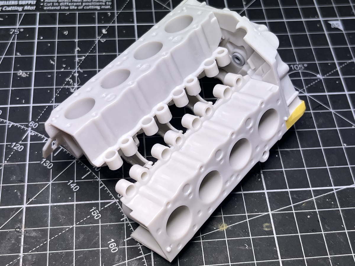
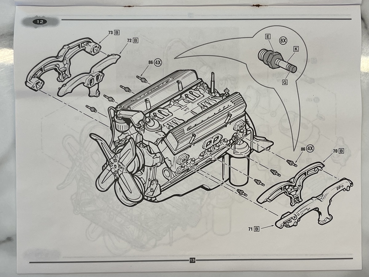
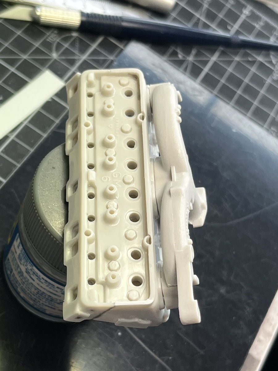
Step 6 (cylinder heads) jumped out at me as another good point to check out what I am up against, only 6 parts and all nice and big but very visible in the final display.
This had me scratching my head a bit until I worked out that the numbering in the instructions for parts 5 and 44 are reversed compared to the sprue numbers
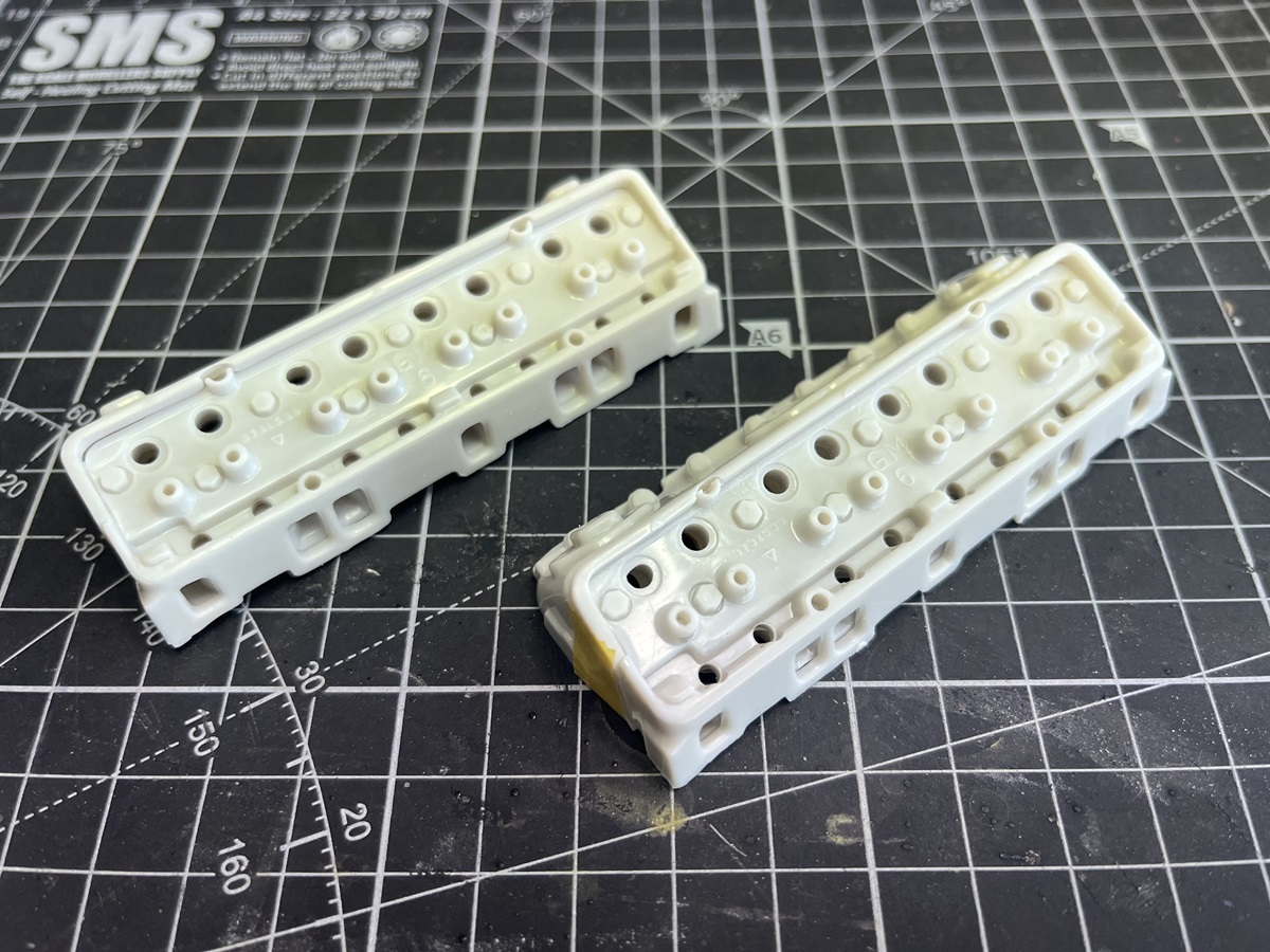
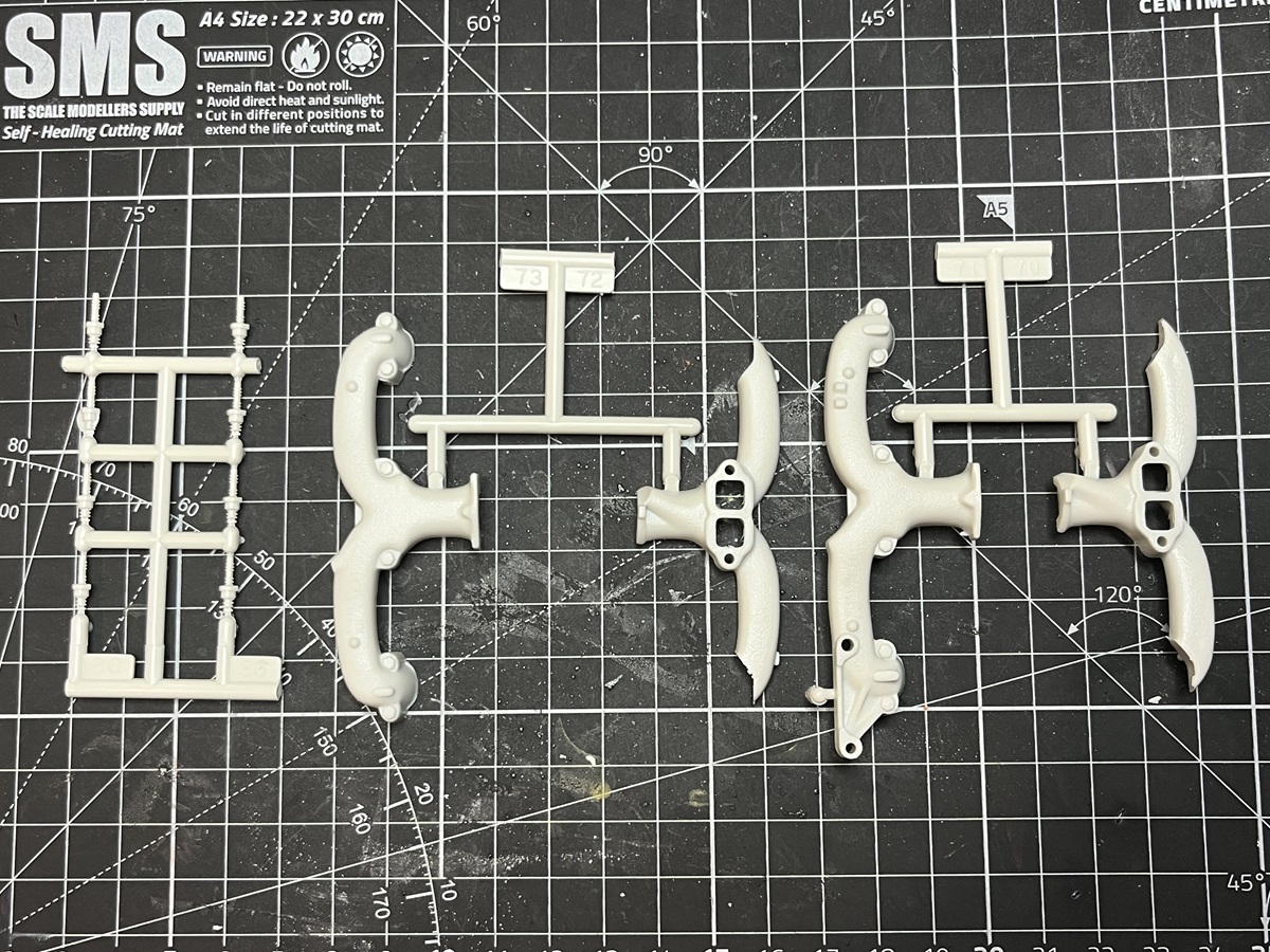
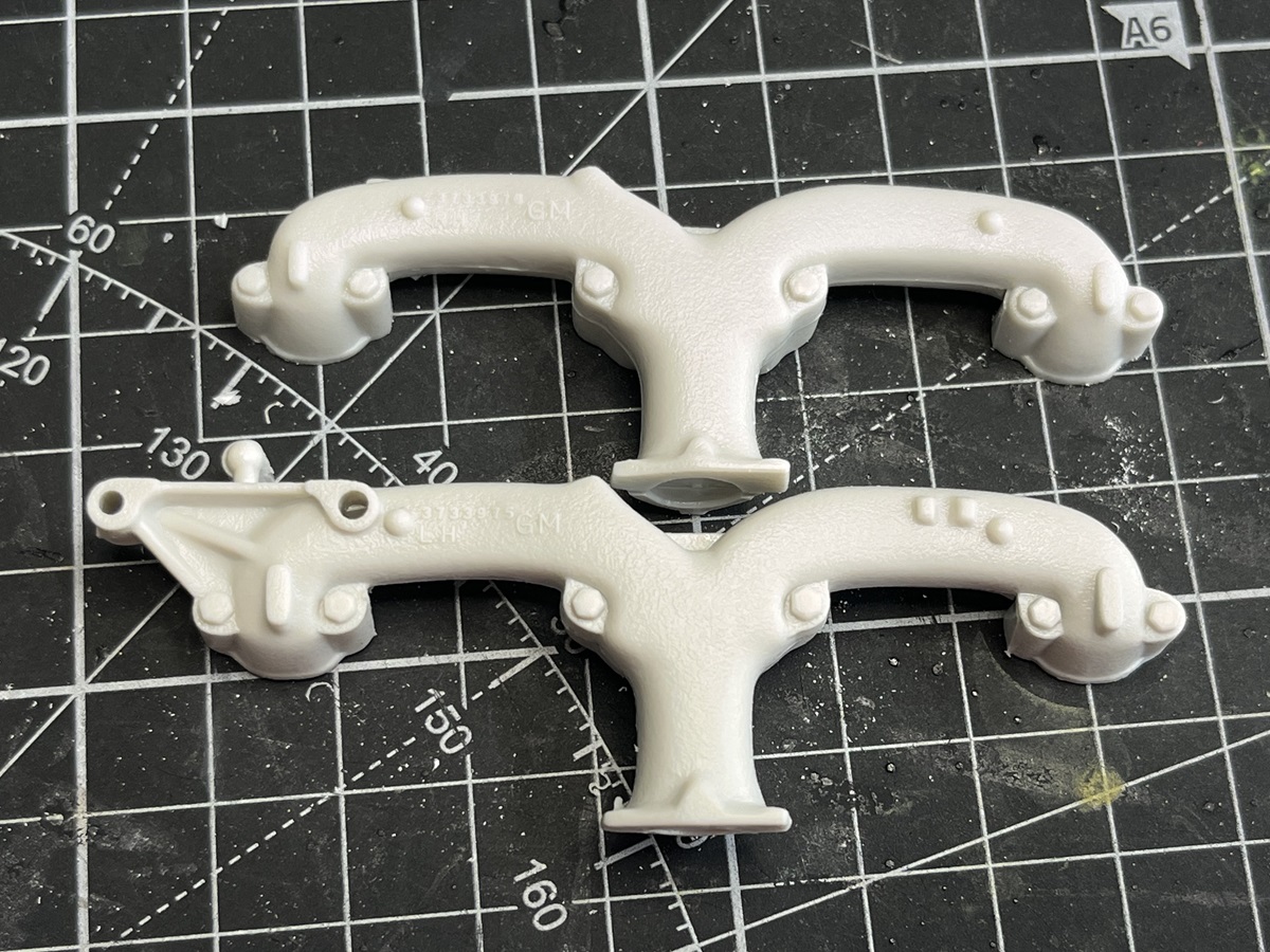
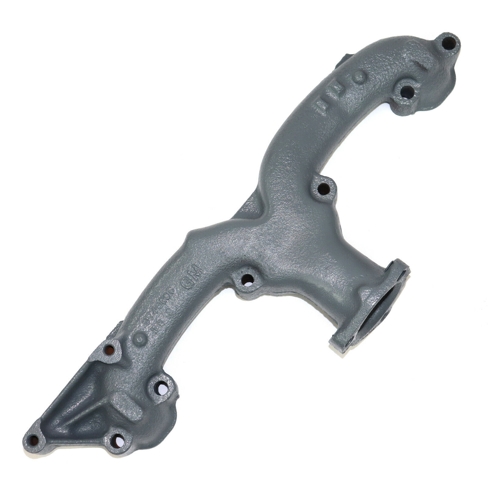
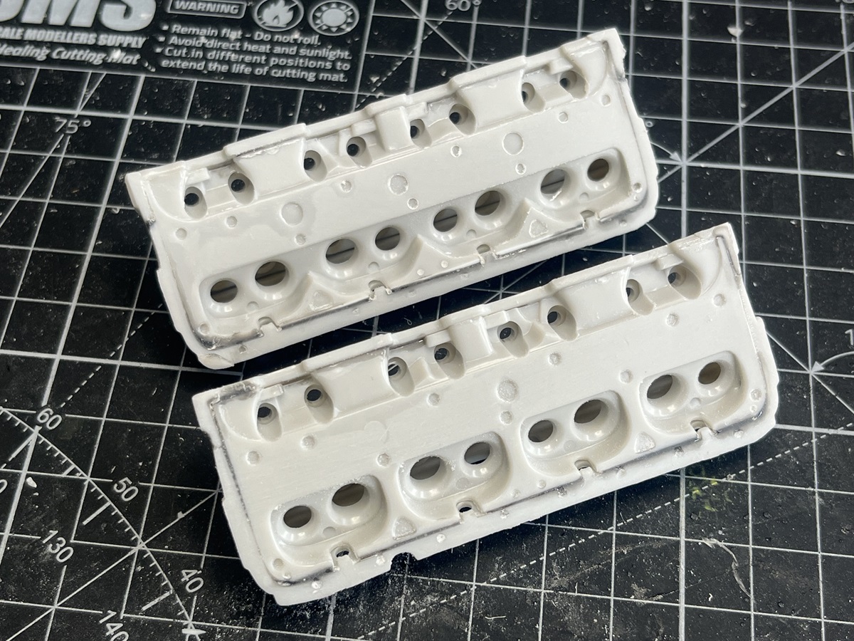
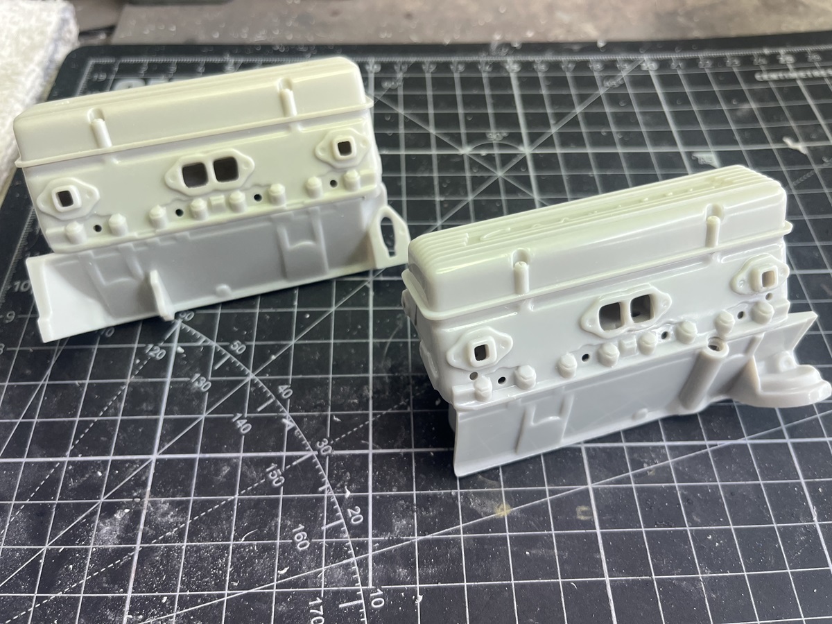
The worst part by far is the moulding and fit of the ends. There are no locating points, just butt-joins, and there are joints, mould lines and sprue points to clean up to get something like the smooth ends of the original items.
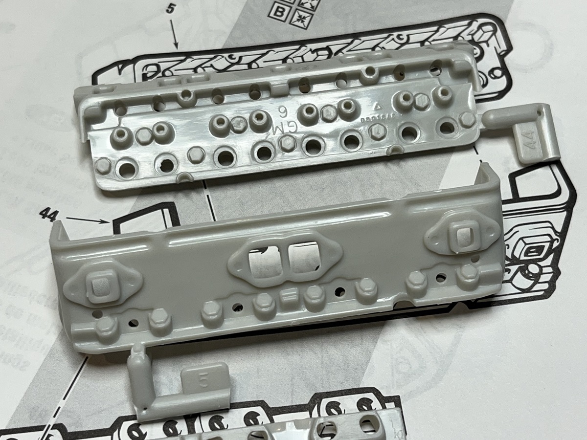
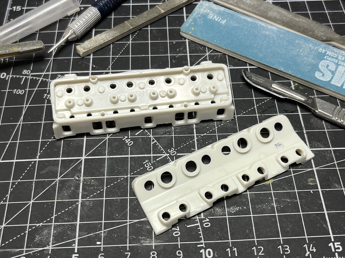
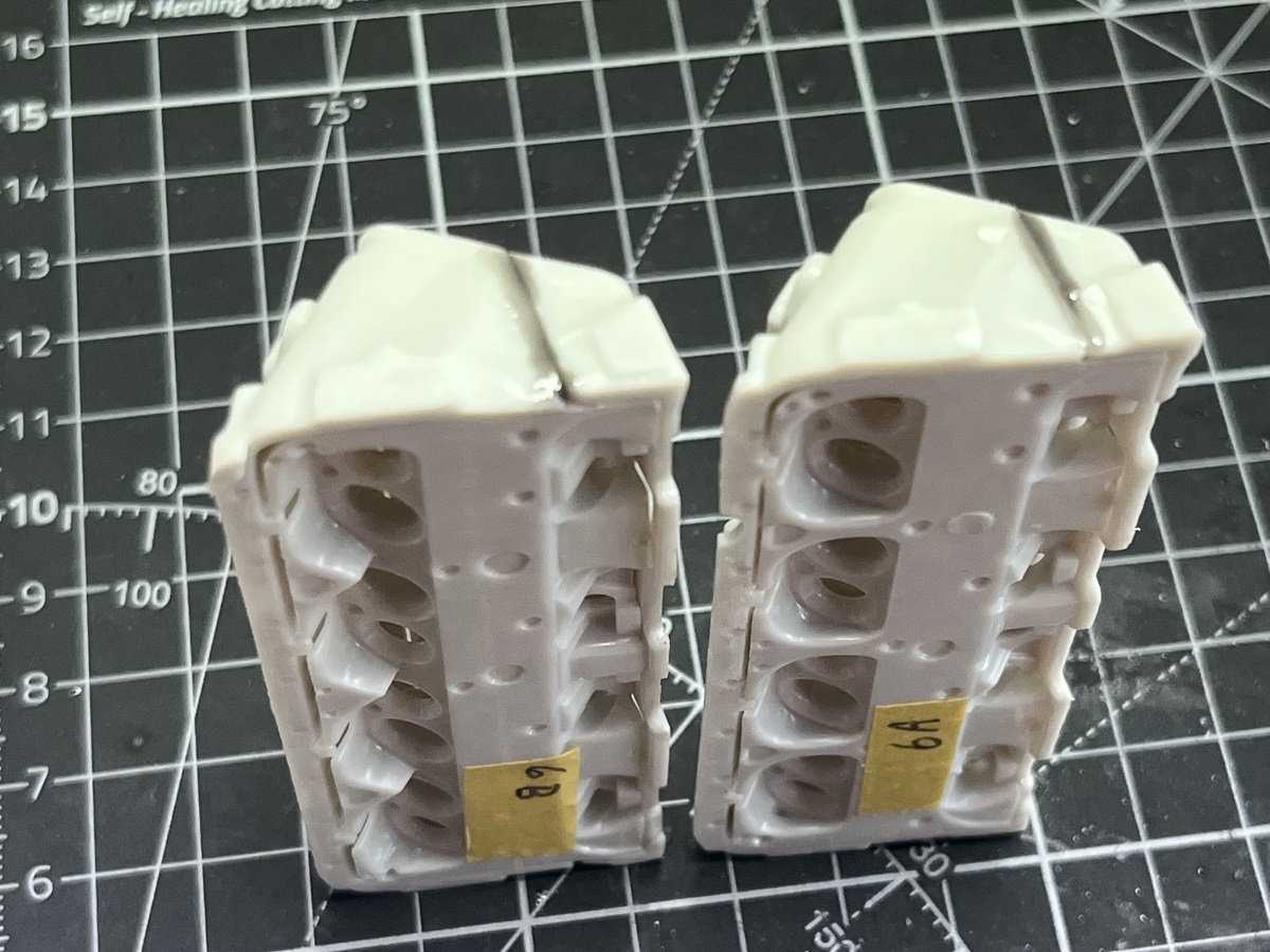
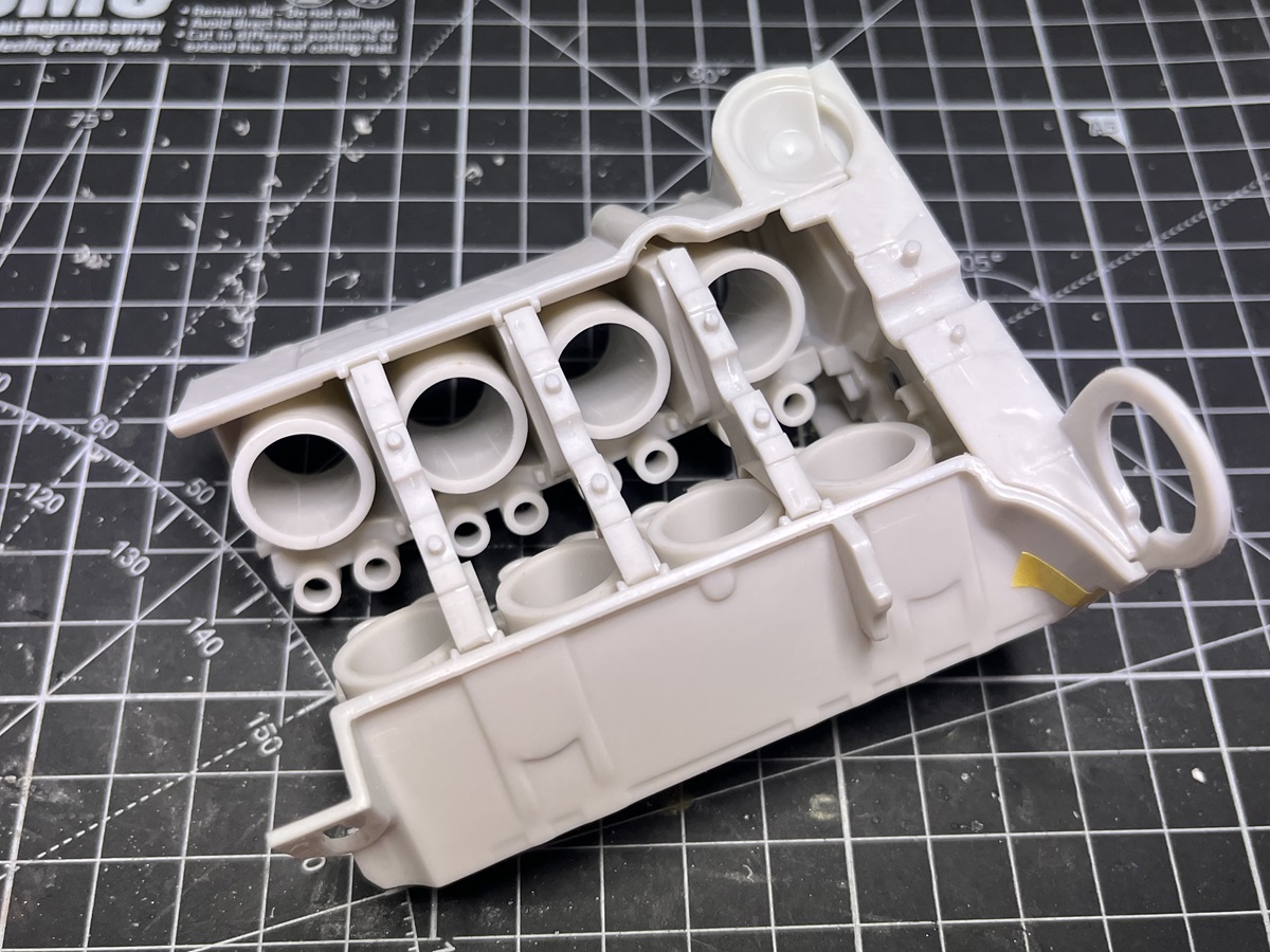
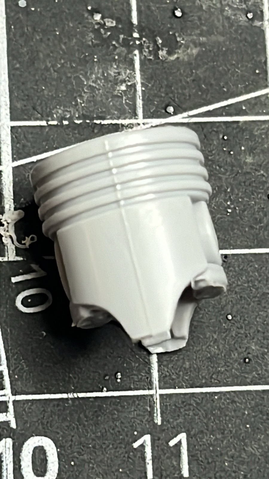
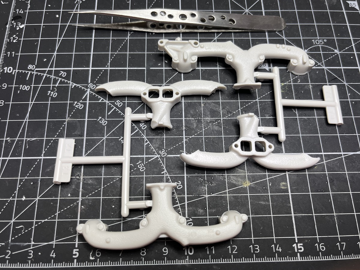
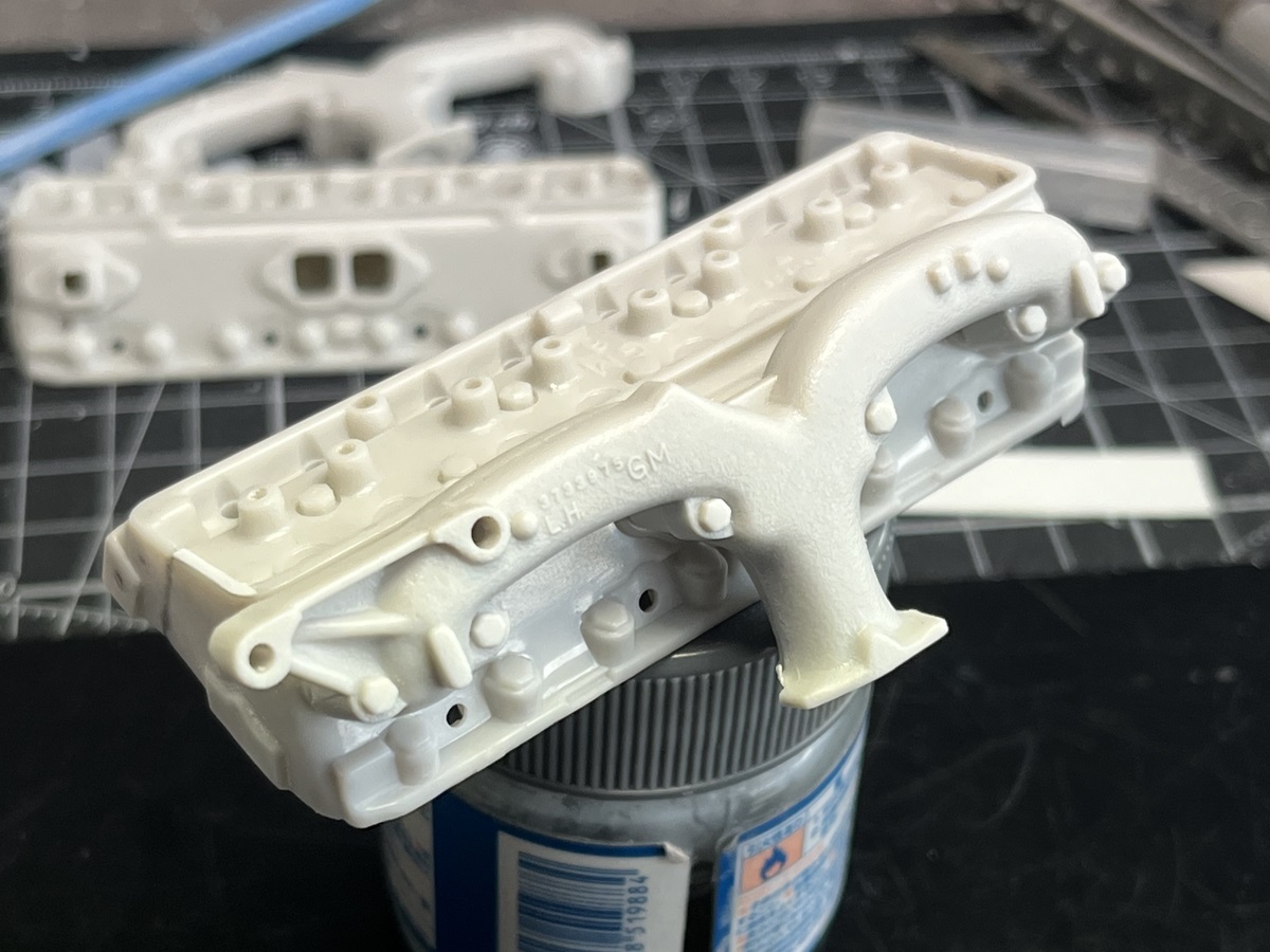
I’ve cemented the bases in to both heads now, in these images you can see the gaps around the bases and I’ve also started work on cleaning up the ends. Sprue Goo to start with to fill the trench along the butt-join.
Hard to pick up in the photos but I used the Dremel with the DSPAIE sanding discs to clean up the ends of the assemblies. I managed to remove the ridges and sprue points without doing any damage to the raised details, then applied some more Sprue Goo to the depressed areas to level things out more.
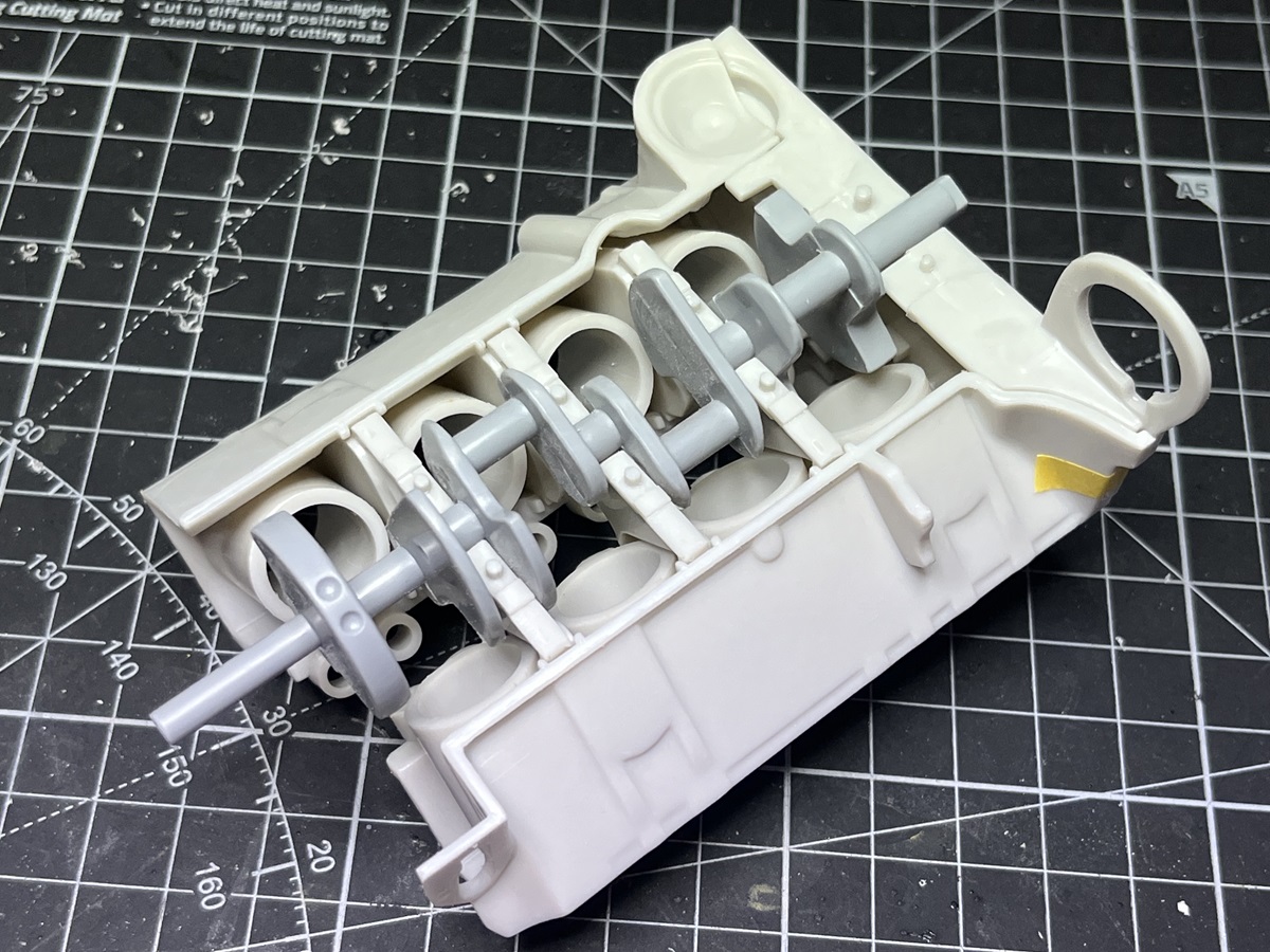
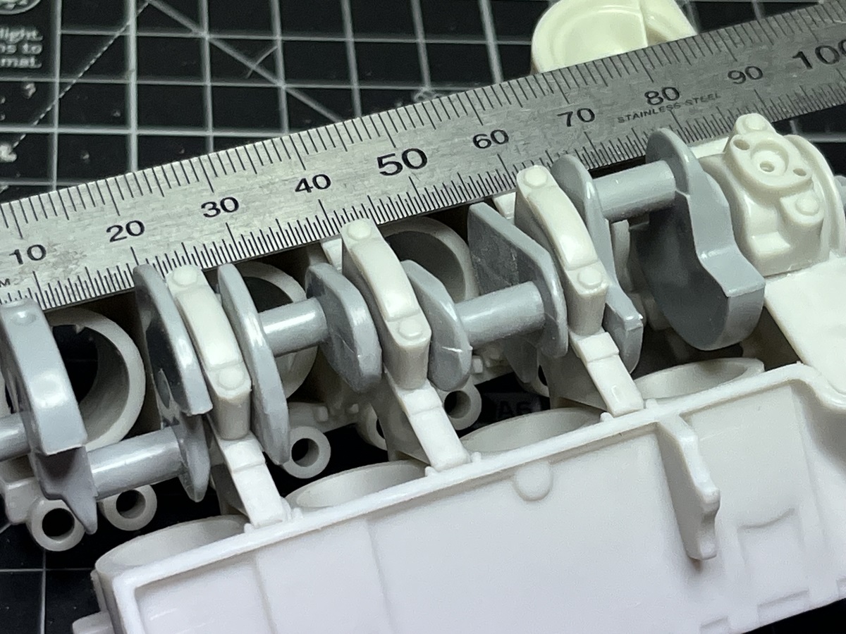
Everything seems to turn just fine, plenty of clearance to paint the parts. There is a slight bend at the far RH end and as it turns the end clamp is lifted slightly (between 8 and 9 on the ruler in the last image), so some tweaking will be needed there.
After cross-matching all of the cylinder head parts I could only get 1 of the eight to fit and line up without surgery. All of the others required “reshaping” of the locating hole to get the cylinder rings to line up. All done now, cemented together and curing. The funny thing is that these will all be hidden inside the cylinders in the end and not visible, but at least I will know that they are done!
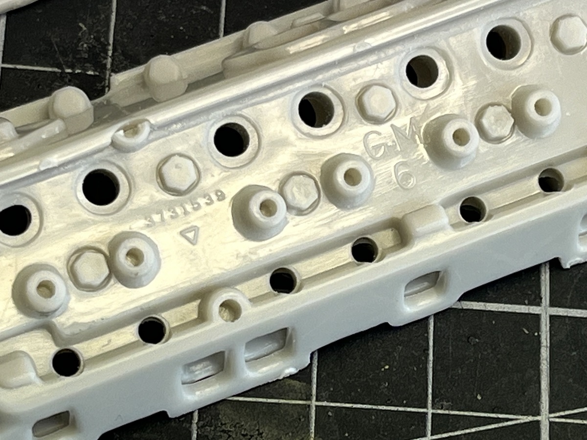
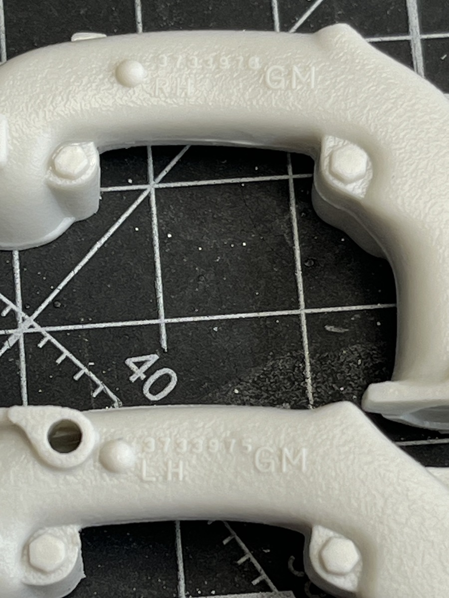
I’m looking forward to seeing this come together and get some paint. The texture and ID codes on the cast parts looks nice, which will hopefully “read” when painted -
Thanks for checking in Nick. The ID codes are very nicely done and will definitely show up well under paint. I have decided that I will go for a weathered finish, but not totally worn out. Some PLW and oil leaks will be in order.
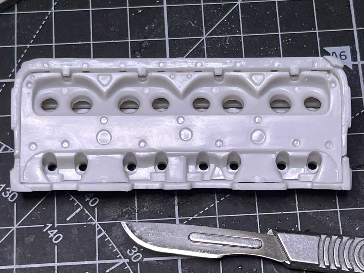
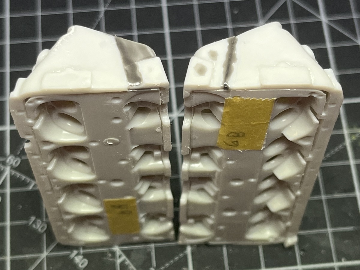
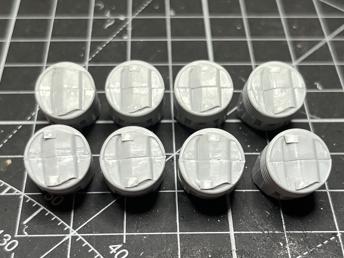
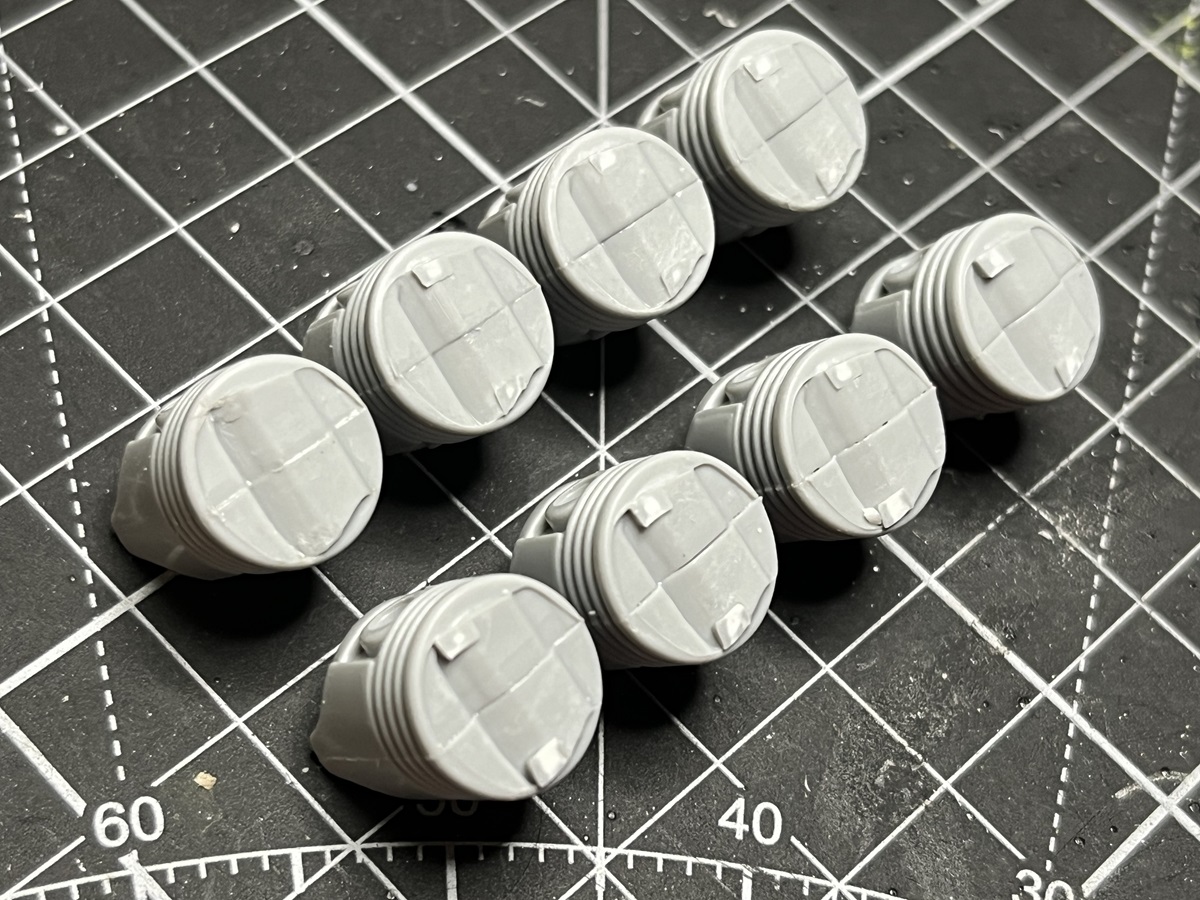
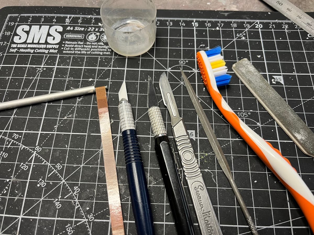
Some more progress to report folks. I’ve spent a fair amount of time cleaning up the cylinder heads now and I think I’m about done. The tool kit used to get here is quite impressive
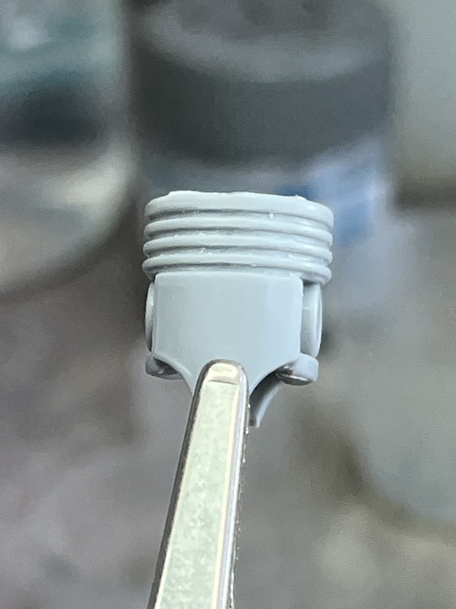
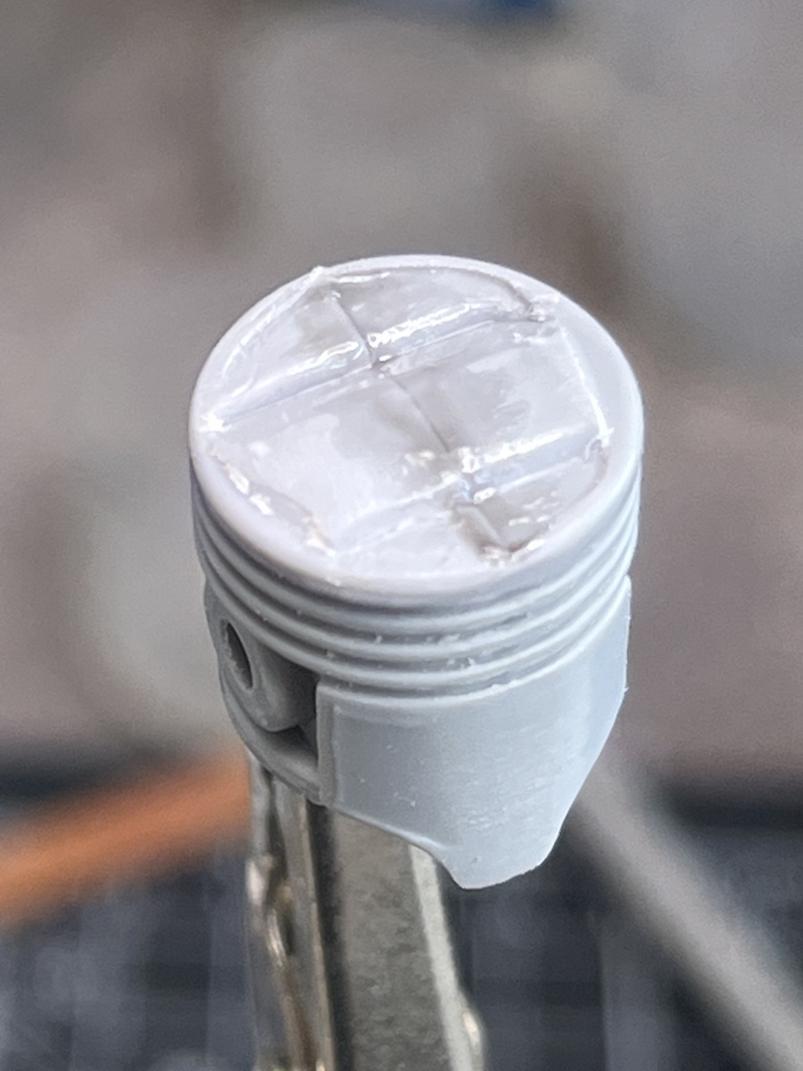
Getting the sides smoothed out and the grooves evened up was a chore, but getting the top faces even close to satisfactory was a nightmare. Given that these will be the only faces visible once assembled I will pay close attention once they are primed. This is an in-progress shot.
Meanwhile, back at Step 6, I’ve added some thin styrene strip to shim the top edge of both ends because the parts didn’t meet up neatly and there’s a small gap in the centre between the rocker cover and the head in both cases.
The rocker covers have 4 locating pins and a neat fit to the cylinder heads, and not much “meat” on the contact surfaces so I won’t be using magnets there.
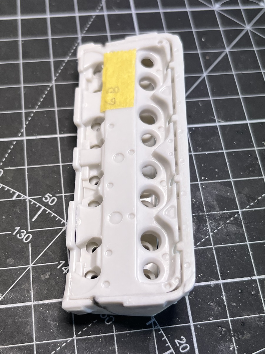
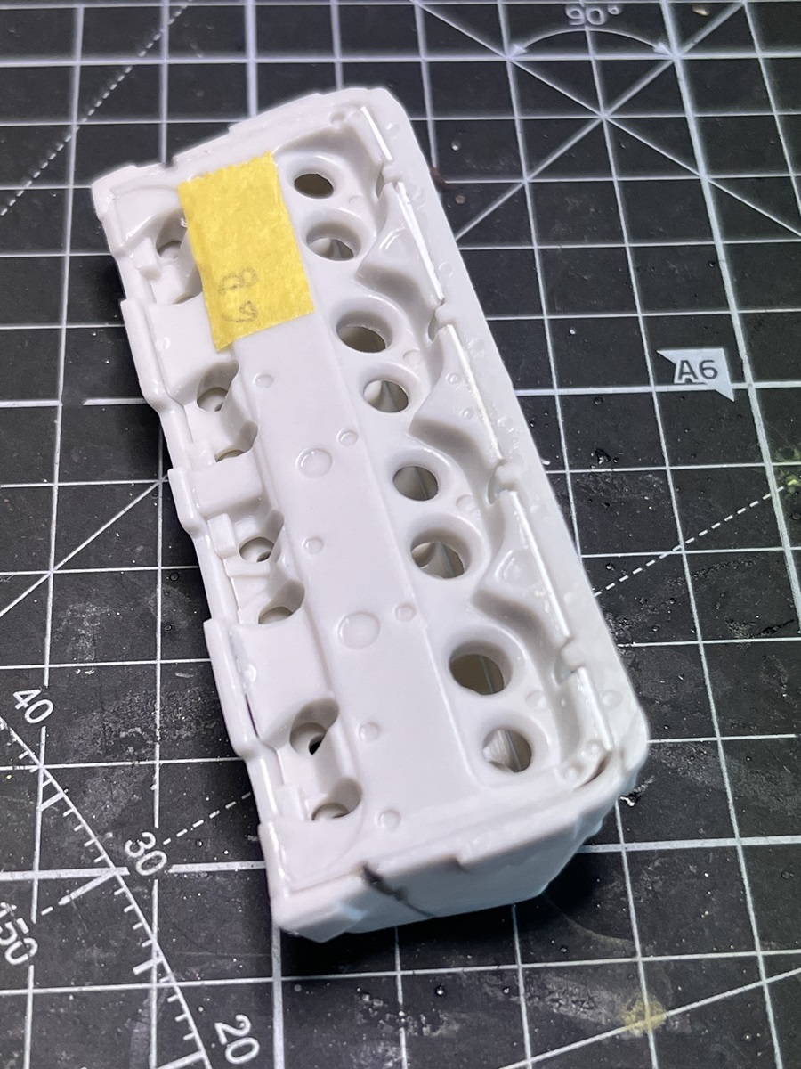
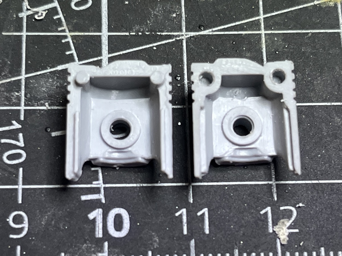
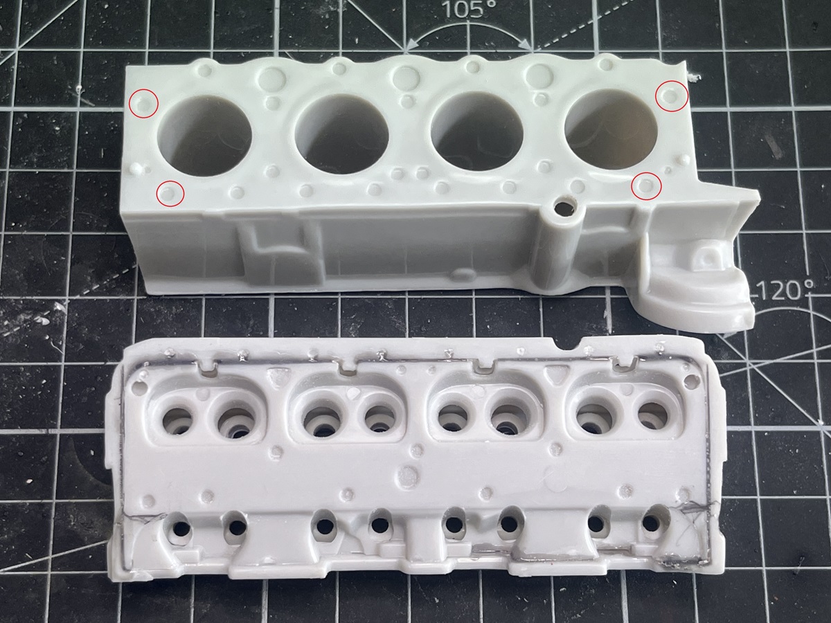
There are surface details on the block halves that are in a convenient place and almost the right diameter to take the magnets (circled in red in the image below), and the corresponding position on the cylinder heads will work as well, so I drilled these out to 2.5 mm and just over 1 mm depth to take a magnet.
The plastic there is just over 1 mm thick so I had to take care not to blast right through. I drilled at 2 mm first then just used the 2.5 mm bit to softly open out the hole instead of actually drilling down, so the bit didn’t “bite” and pull through too far. All going according to plan so far, magnets are set in place with a drop of CA.
The next part of my cunning plan is to put a tiny drop of red paint in the middle of each magnet then locate the cylinder heads to transfer the location of the magnets to the heads.