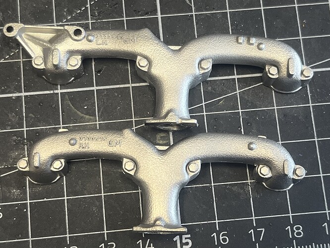
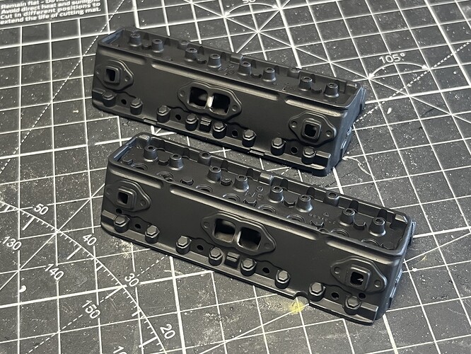
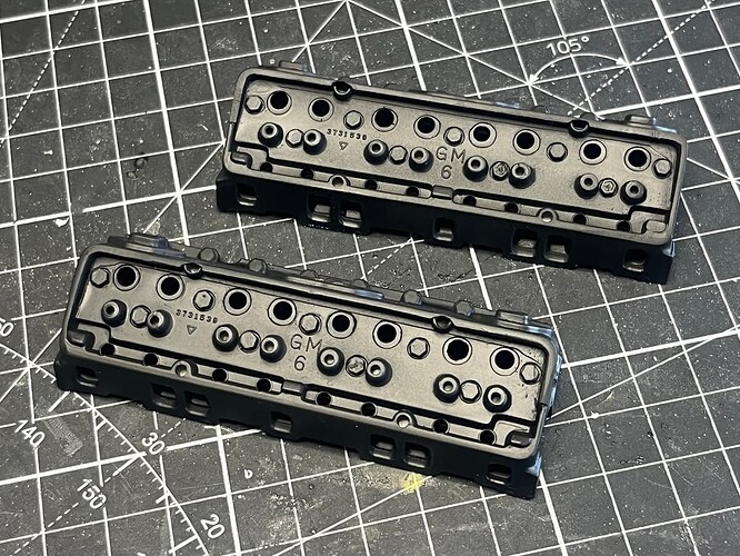
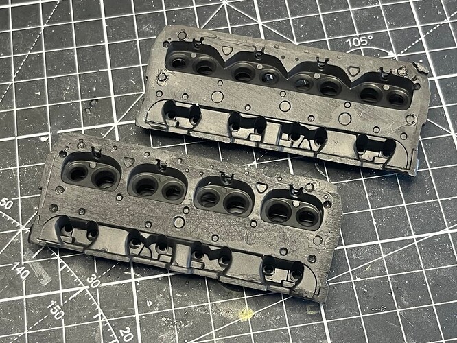
Noice!
The really new and interesting/challenging aspect of this build to me is that it has become a serious engineering conundrum. To what level do I want this to break down? Which sub assemblies need to be permanently fixed in place? Will the parts fit cleanly enough to look good if they aren’t cemented together? I need to constantly scan forwards through the instructions, investigate and test fit parts from future steps to make decisions on current stages. More on this later in the post . . . .
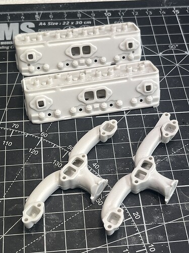
Step 12 (exhaust manifolds) continues.
Firstly, a bit of a head-scratching moment ![]()
The exhaust manifold flanges have very neatly formed locating holes either side of the exhaust ports that fit perfectly onto . . . . . . wait for it . . . . NOTHING ![]()
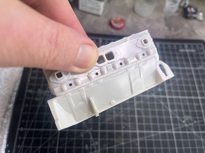
I’m thinking this must be a change in the decisions at design stage part way through as there are small recessed marks at the corresponding points on the cylinder heads, not locating pins. Instead, there are square raised lugs on the outer ports of the cylinder heads (that locate the manifolds quite well).
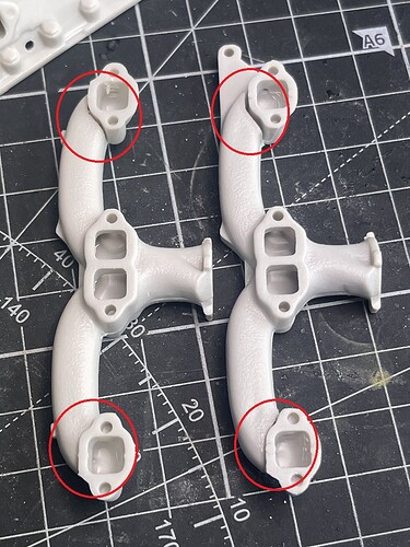
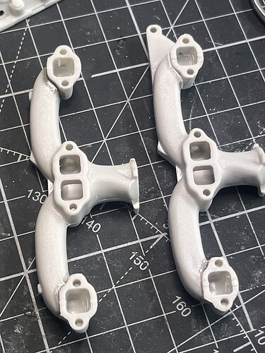
There are gaps at the back of each manifold join that need to be addressed (circled in red), sprue goo was used for 3 of these but one was wide enough that some styrene sheet was needed to fill first.
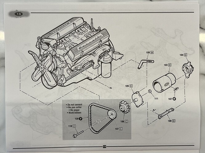
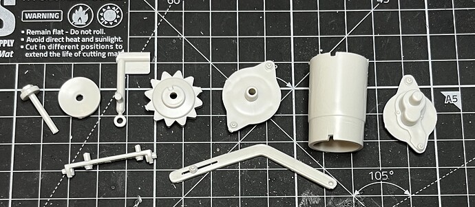
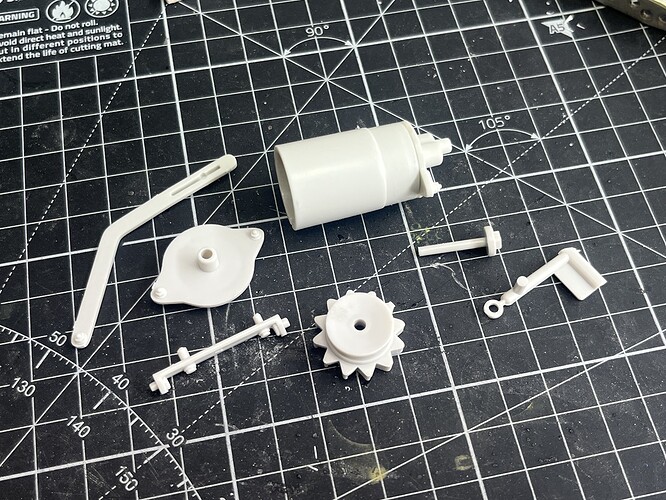
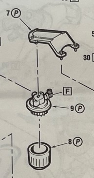
Step 13 (the generator, NOT the alternator!).
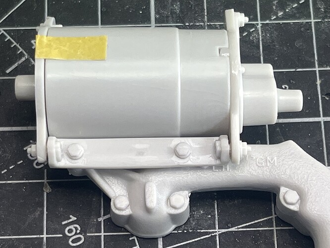
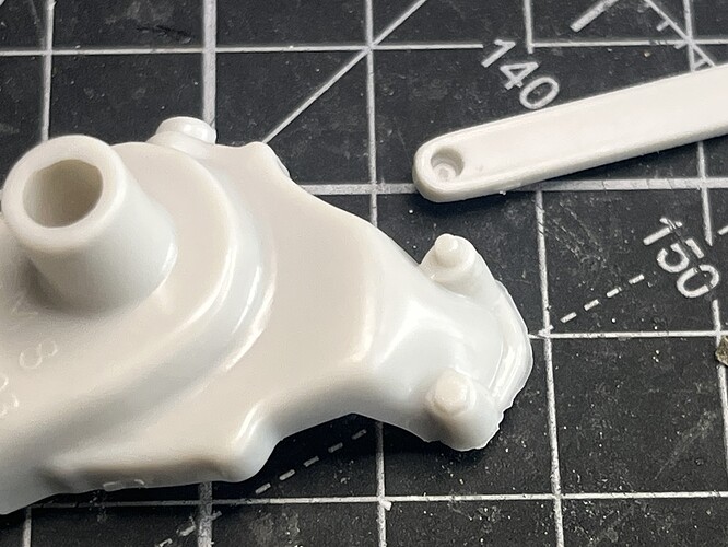
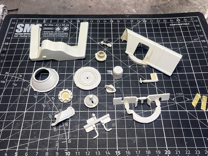
Parts cleaned up and assembled to the point where primer/paint is required.
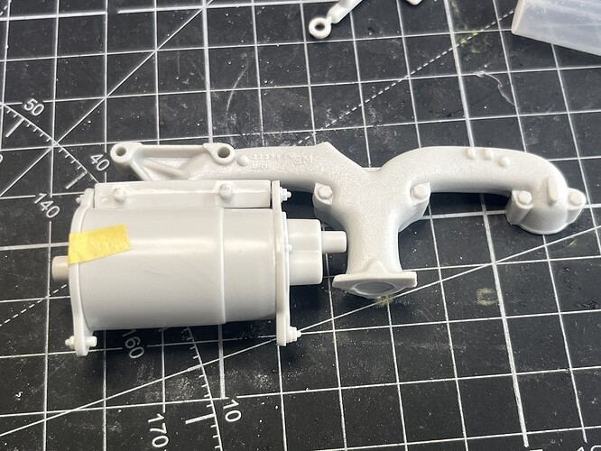
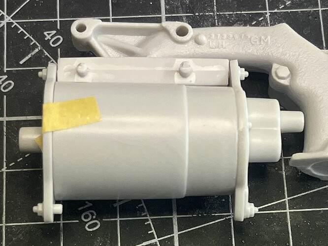
Test fit of generator to manifold.
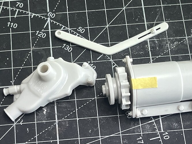
Generator adjustment slide mount fit to water pump housing (NO magical levitating generator on this build ![]() ).
).
Now comes the forward-planning and decision making time, and question time -
Do I want to be able to remove the exhaust manifolds from the cylinder heads?
Ideally yes, this will enable viewing through the exhaust ports to see the valve stems inside.
Do I want to be able to remove the generator assembly from the LHS exhaust manifold?
Ideally yes, the generator mount bracket has 2 strong locating pins that fit neatly into the integral mount on the manifold, should be easy (famous last words).
Are there suitable locating points for magnets for me to be able to do either of these things?
Yes, but it will require filling the location pin holes on the manifolds and the generator slide mount.
Then it struck me, all of this grand planning comes down to one big question . . . . . . will any of this stand up to the force applied by the vinyl fan belt ???
If the fan belt is a tight fit, it will be pulling inwards on the generator pulley, which in turn will be applying leverage on the generator mount bracket and in turn on the exhaust manifolds. Will the location pins be secure enough and the magnets be strong enough to resist this leverage?
The kicker is, the only way to find out is to complete the build and fit the belt ![]()
I will continue with sub assemblies and painting while I have another coffee and ponder this earth-shattering (and potentially plan-shattering) revelation.
Cheers, D
Still pondering life choices, but moving forward with some minor tasks at the same time.
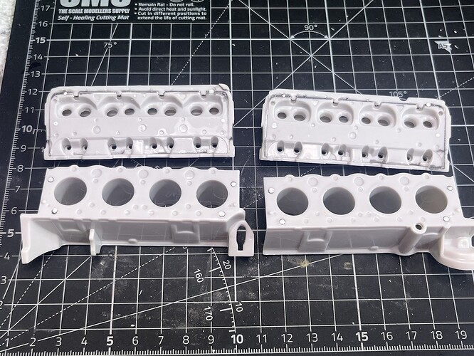
I used a toothpick to put a small drop of white enamel on each magnet on the block halves then located the cylinder heads to transfer the corresponding point. Seemed to work fine, once the enamel is cured I will drill out the holes and fit the second set of magnets.
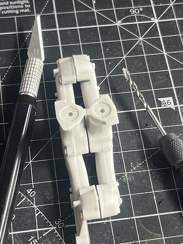
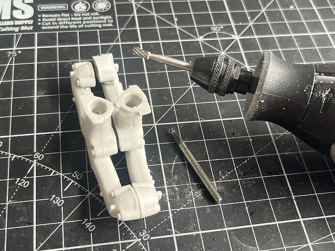
I also step-drilled the exhaust manifold outlets up to a diameter where I could use the Dremel with an end mill to grind out the blank ends and some internal plastic.
Cheers, D
Looking great Damian. I like the magnet idea and hope the works out. I remembering doing all that internal work on the Cosworth V8 and then sealing it all up. How will it work taking the heads off once you are all wired up. Will the ignition cords be a sort of slip on arrangement or is there another way of doing this?
cheers
Michael
Thanks Michael!
The ignition leads and other electrical lines all have plug boots like the 1:1 items so they can be installed and removed easily! I’m sure over time they will become brittle and start to deteriorate, but by that time I can probably come up with a solution to replace them.
Cheers, D
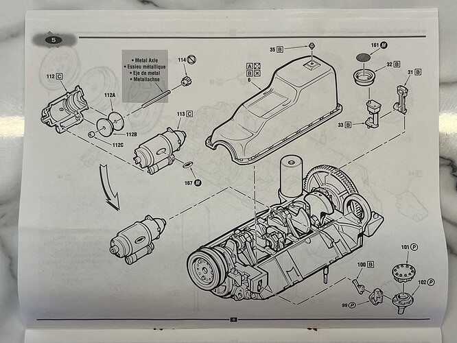
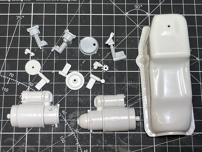
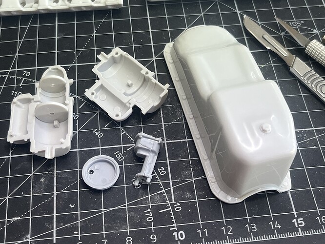
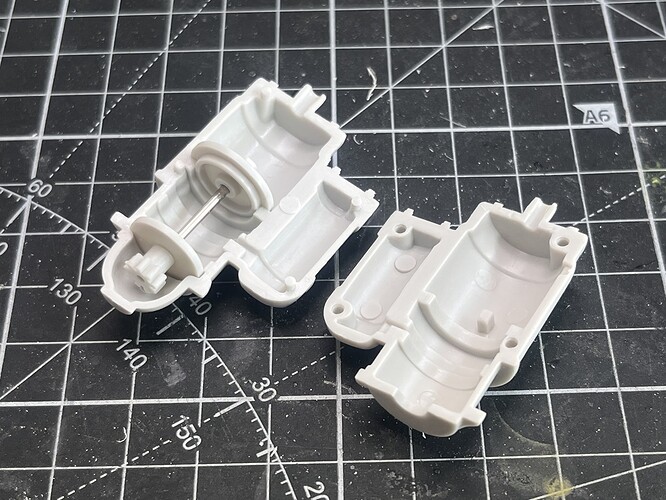
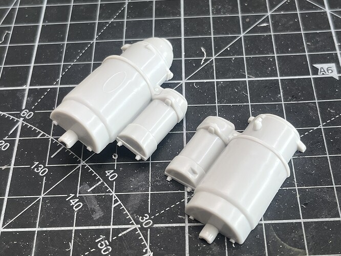
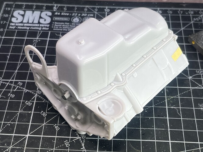
Still jumping around cleaning up parts and setting up sub assemblies, here is some work on Step 5 (Oil Pan, Oil Pick-up and Starter Motor).
And yes, the magnets worked! ![]()
I can’t upload a video but here you can see the engine block half firmly attached and correctly located being lifted by the cylinder head.
Very happy with the way this worked out, and I will do the same thing to hold the oil pan to the bottom of the block once the block is assembled.
Cheers, D
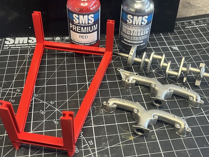
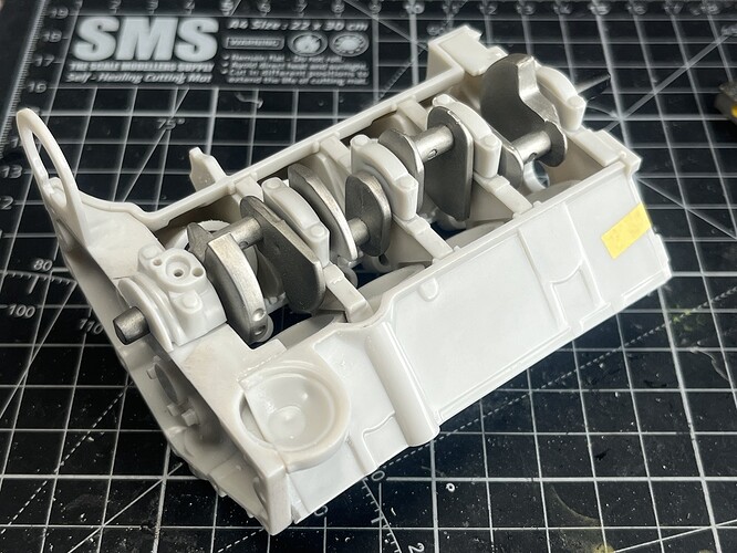
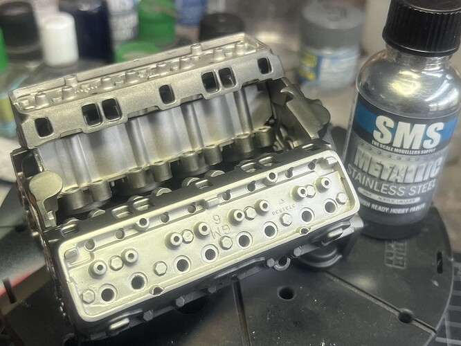
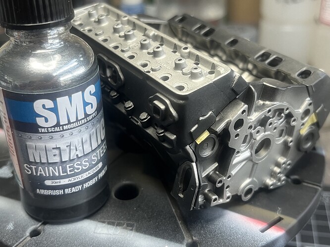
A spot of painting done, SMS Red on the engine stand (wheels are painted black and masked to be detail painted later), and SMS Stainless Steel on the crank and exhaust manifolds. I wanted something a bit darker than Steel and the texture on the manifolds dulls it off nicely.
Cheers, D
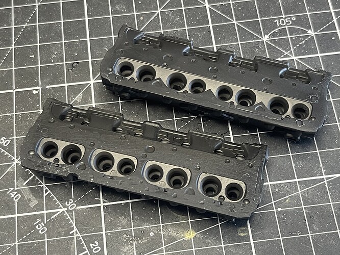
A little progress, the cylinder heads are in primer now. I will do some work on the bottom faces, they are a bit ugly ![]()
Cheers, D
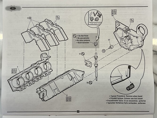
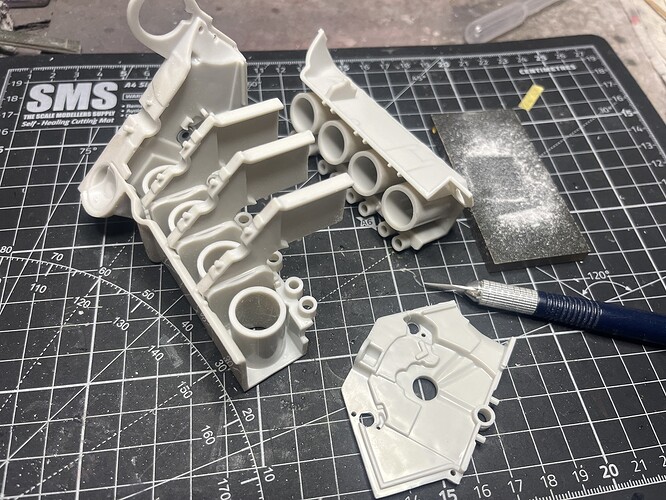
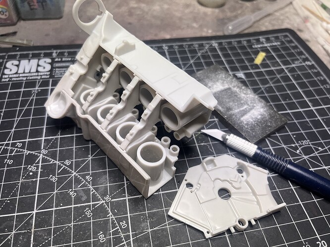
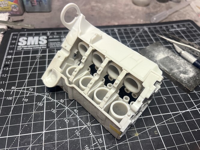
Lets jump back to Step 1 and see if we can get the main engine block parts to line up !!
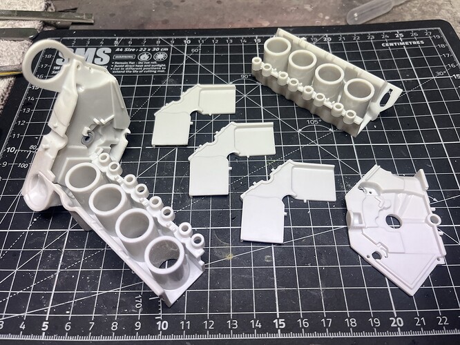
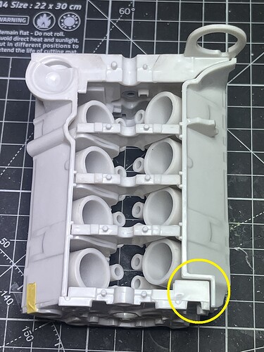
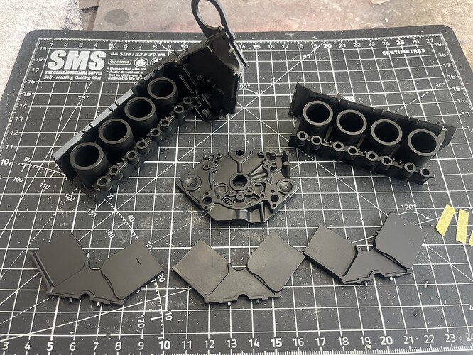
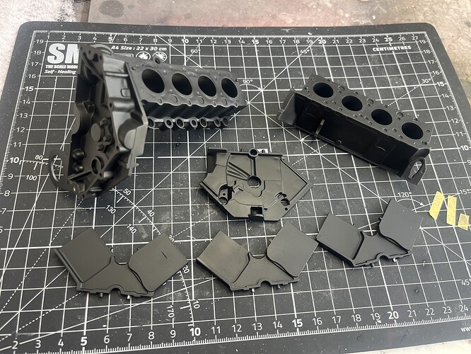
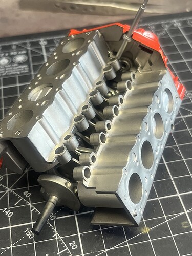
Parts #1 and #14 have been cleaned up and cemented together to give me a solid foundation to start with, now I want to see if the 3 main supports (Parts #3) and the second cylinder bank (Part #2) will fit and line up before I go much further.
As suspected, we have gappage (yellow circle) so tonights mission was to sand and scrape and test fit (set to repeat) until things line up neatly.
My method was to work on the supports one at a time so that each one would fit and allow the front end of the engine block to sit neatly in place, then move on to the next one. There was some interference right at the bottom of the gap between the cylinders that could not be accessed, so both ends of each support had to be shaped with the ceramic scraper until it settled in place. They were all slightly different but after an hour or so I think I got it to where I want it.
Now I need to test fit all of the Step 1, 2 and 3 sub assemblies and work through the best sequence for paint and assembly.
Cheers, D
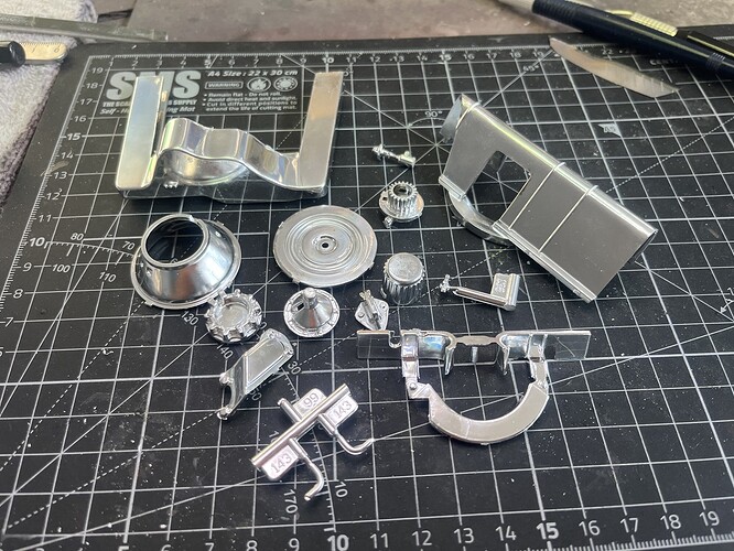
I had a good look at the plated sprue and found while most of the chrome looked quite good, a few conspicuous spots had a bit of wear and scratching, and the sprue connection points are large and “inconvenient” to say the least ![]()
Time for a bath in my favourite chrome-be-gone, Mr Muscle Oven Cleaner. See you in a few hours ![]()
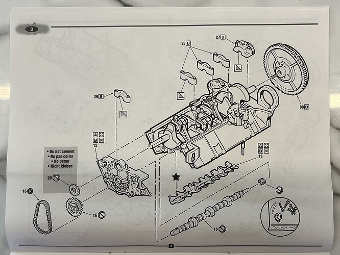
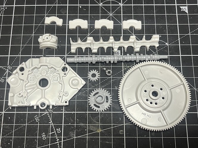
Step 3 is an assembly step with no sub-assemblies, but a few parts requiring clean-up and paint prior.
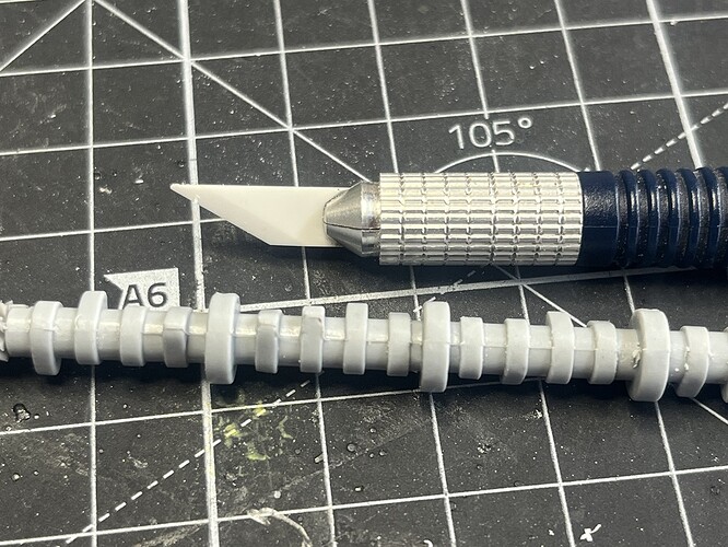
The camshaft in particular has a nasty seam down both sides. I used a sanding stick to tidy up the outside of the lobes, and the SMS Ceramic Scraper to get to the tight recesses. Still a WIP.
Test fit of the crankshaft to the block with the retaining brackets looks ok, spins freely.
Step 5 has the oil pick-up and sump, fuel pump and starter.
Test fit of the sump to the block shows a reasonable fit, but some work to do to get a tight join. I’m hoping to use the magnets again here so the sump can be removed to show the bottom end. We will see ![]()
![]()
Cheers, D
Chrome-be-gone!
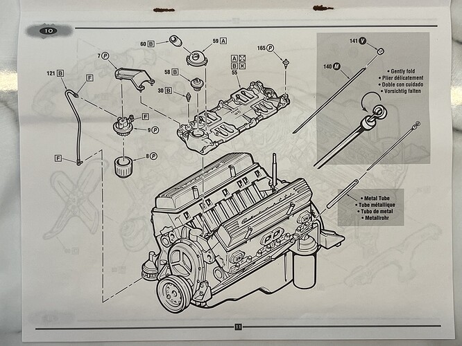
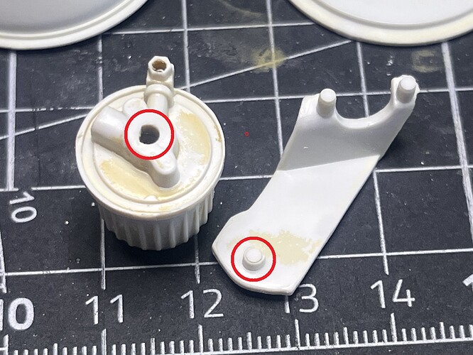
Cleaning up and assembling the fuel filter, we find AMT/ERTL engineers attention to detail ![]() The fuel filter mount bracket has a locating pin that is not quite round so that it can only be inserted in one position. Problem is that the locating hole on the fuel filter assembly has the hole orientation backwards
The fuel filter mount bracket has a locating pin that is not quite round so that it can only be inserted in one position. Problem is that the locating hole on the fuel filter assembly has the hole orientation backwards ![]()
![]()
![]() This will have the fuel line on the forward side of the filter rather than the back. Oh well, nothing a small drill bit won’t fix, but a trap if you’re not watching.
This will have the fuel line on the forward side of the filter rather than the back. Oh well, nothing a small drill bit won’t fix, but a trap if you’re not watching.
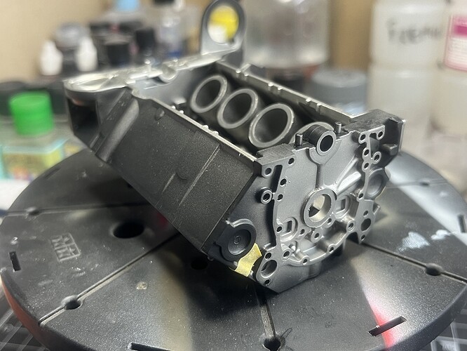
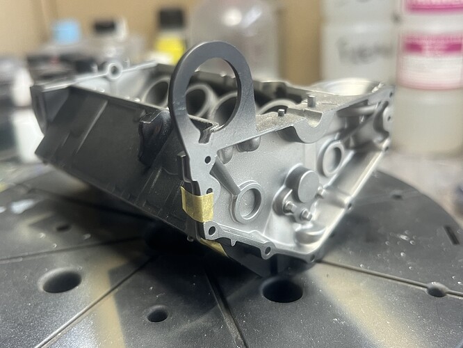
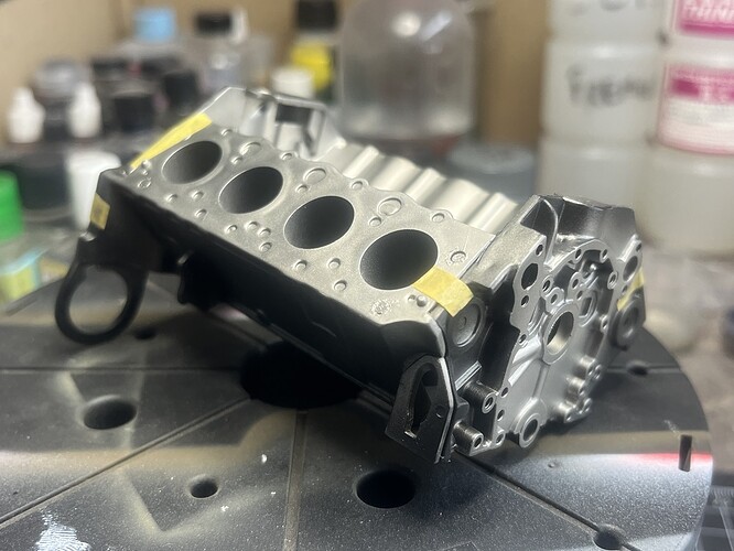
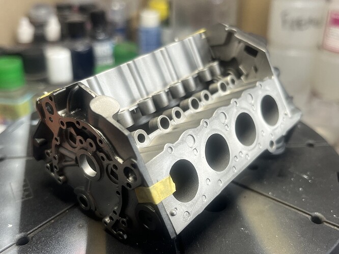
All the way back to Step 1 now, main engine block parts are primed ready for paint.
Funny how things line up! I turned 57 two days ago, and here I am working on the big '57 Corvette engine having just completed the '57 Corvette build. Maybe I should start a '57 Bel Air build now as well ![]()
![]()
![]()
![]()
Cheers, D
Or play the number 57 on the lotto …
Hey you lot, I hope I’m not making people dizzy jumping back and forth between the Steps here ![]()
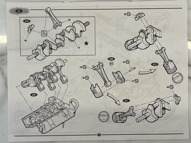
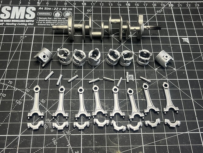
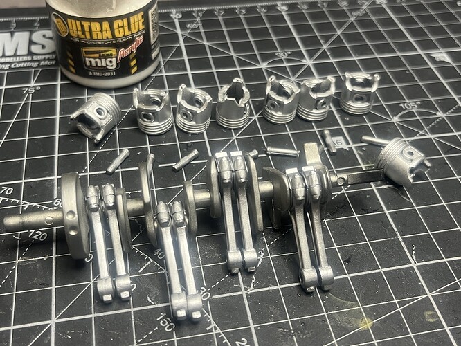
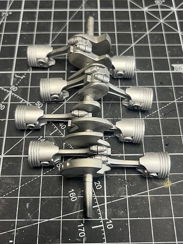
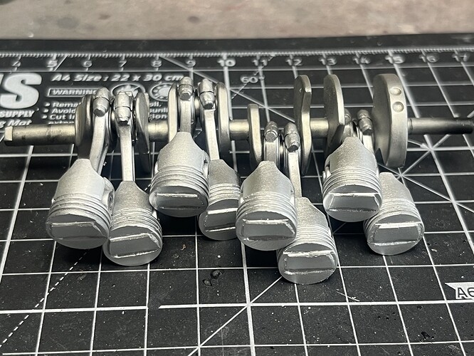
No? Ok, lets get Step 2 completed then ![]()
Some of the piston heads are a bit ugly, but it’s one of those never-ending spirals where I fix one bit and it creates another mismatch or imbalance so I’m chasing my tail. It is what it is now!
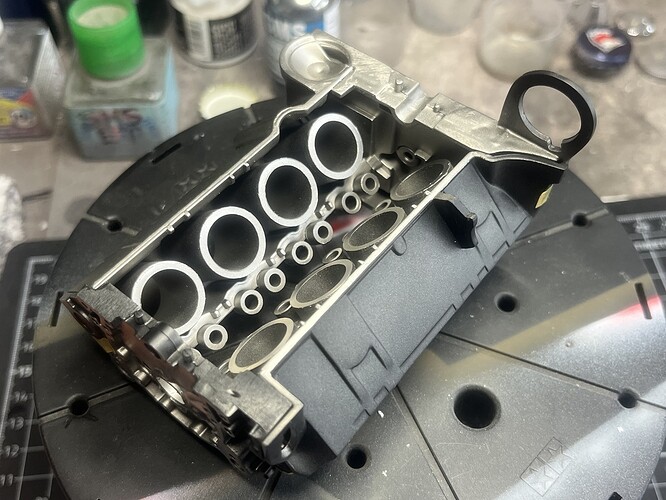
I also gave the internal surfaces of the main block a shot of SMS Stainless Steel and a dry test fit with the heads.
Pretty happy with the result here, need to mask off the S/S now and spray the Chevy Engine Orange then I can get on to some serious assembly ![]()
Cheers, D
wow ![]() D, you are doing a heck of a job on this - the various metal shades are looking really good. To your point about the pistons, yes, I get it, which is a bummer - as in yes, once you fix one, obviously you’ll need to do the next seven - and then, hmmmm, the valley where the manifold meets the block and valve heads looks, a bit off, and by the way, the valve heads, well, I could…
D, you are doing a heck of a job on this - the various metal shades are looking really good. To your point about the pistons, yes, I get it, which is a bummer - as in yes, once you fix one, obviously you’ll need to do the next seven - and then, hmmmm, the valley where the manifold meets the block and valve heads looks, a bit off, and by the way, the valve heads, well, I could… ![]()
![]()
![]()
![]() The never ending struggle!
The never ending struggle!
Looking forward to the next post!
Cheers
Nick
Thanks Nick!
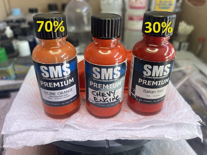
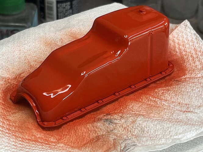
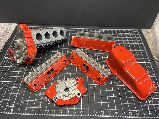
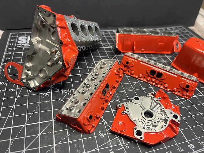
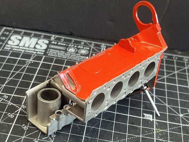
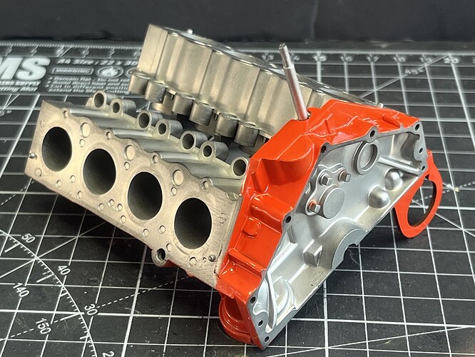
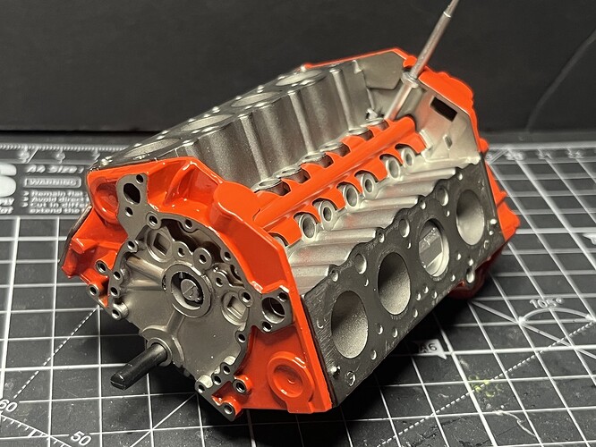
Wow, where did the last 3 weeks go? I wanted to get some colour down so I mixed up a batch of Chevy Engine Orange/Red and fired it at the oil pan to see how it looks.
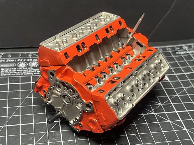
Happy with that, so after a lot of masking I laid the colour down on the main block and heads as well, followed by a clear gloss to protect it from my fumbling fingers.
Almost ready to start the main assembly on Step 1 now ![]()
Cheers, D
All I can say is that looks incredibly good - wow ![]()
![]() It looks like you just set the real parts out for assembly - that looks great - the markings on your work mat is the only reason you wouldn’t expect to see this on a workbench - again, wow!
It looks like you just set the real parts out for assembly - that looks great - the markings on your work mat is the only reason you wouldn’t expect to see this on a workbench - again, wow!
Cheers
Nick
this has got to be the best looking small block I have ever seen. If one didn’t have the sense of scale, they would think those were real heads. absolutely beautiful.
Thanks you gentlemen, I really appreciate the feedback!
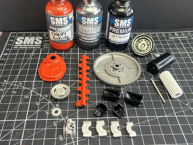
I put some paint down on parts for some future steps.
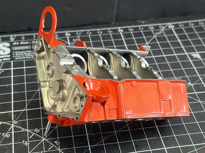
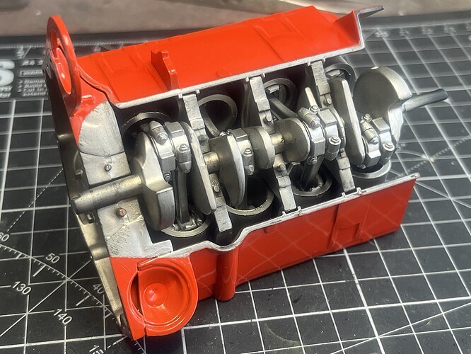
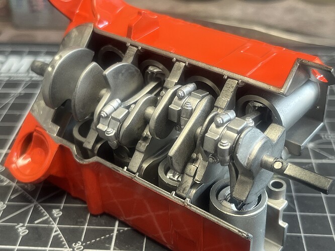
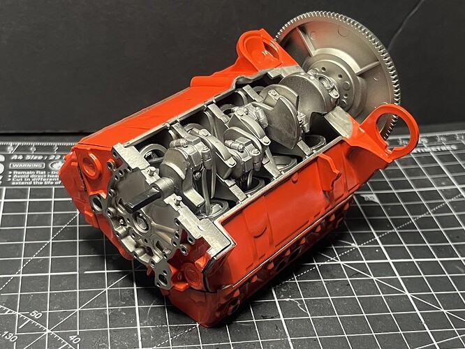
Once the paint was cured properly on the main parts I completed assembly on Step 1 . . . . YAY!!
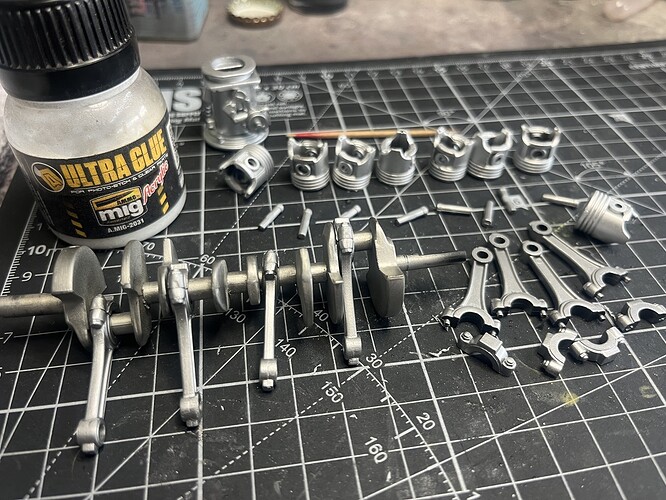
Once Step 1 assembly was fully cured I set up the Step 2 assembly (pistons, rods and crankshaft).
The crankshaft has a slight bend in it, I’ve warmed it up and straightened it a couple of times but it’s determined to stay bent. I’m hoping that the hold-down brackets in Step 3 will keep it lined up so it spins neatly.
Cheers, D
That metallic colour you have used Damian looks so realistic. As the others said, that could easily pass for a refurbed block on a workbench. Amazing!
cheers
Michael
