@LeoCmdr - Jason,
Thank you for dropping by and having a look at my smaller scale version T-15 and even in 1/72nd scale it’s an imposing beast. 
@FirstCircle - Matthew,
Yes indeed at times I feel like I have “bitten off more than I should chew” but it is slowly progressing. The beast is similar enough to the Terminator and one can definitely see that it’s kit design comes from the same “house” or “stable”, so to speak. The parts locating features appear to be all over the spectrum. From small but precise fit to sloppy to virtually non existent. My gripping tool has proved a “heaven sent” at times and has only “dropped” a part once or twice that I recall. The five claws are virtually locked in place by an appropriately strong spring with a simple but ingenious locking system. You might be surprised at the size and shape of some of the parts I have managed to clean up while being held by its jaws. As for where I might cleanup parts, that all depends. The part D37 that I glued on before cleaning was too small even for my gripper and only measures approximately 4 mm long by .75 mm wide. Cleaning it after it was safely “welded” in place seemed like the logical choice. 
@Braille - Eddy,
Yes this version of the Armata is quite impressive in size and its defensive systems. The APS system can supposedly intercept APDS shot fired from 120 mm guns. The moulding in general is quite nice and detailed and one definitely needs to be prepared to deal with some minuscule parts. Of course that’s what makes this scale so fun?  While the hull top hatches are positionable I fear the rear ramp to the troop compartment is moulded closed. Then again that area is quite busy as there is a troop door in the ramp plus both ramp and door are covered by bar armour.
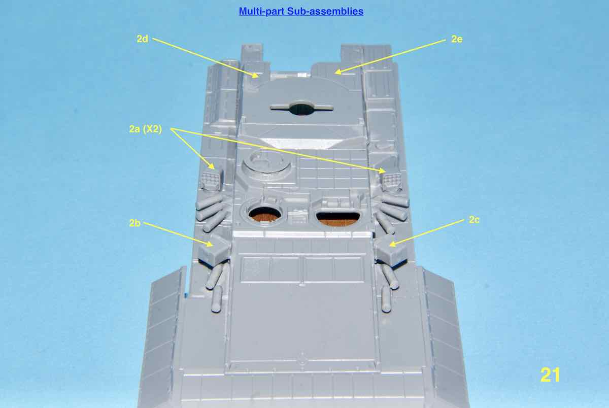
Now it has been a while since I’ve updated this build but I was dealing with assembling various sub-assemblies from STEP 2. Not only were many of the parts small but because of the size it made it difficult to handle them to sit right.
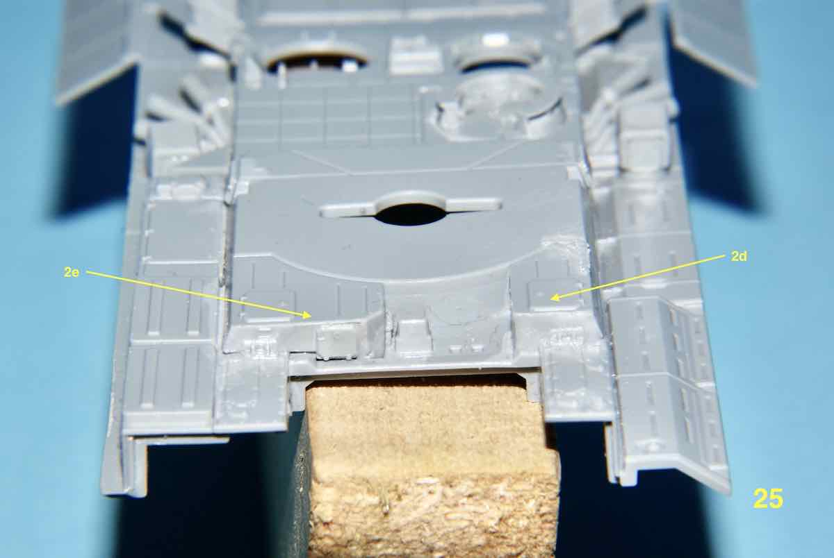
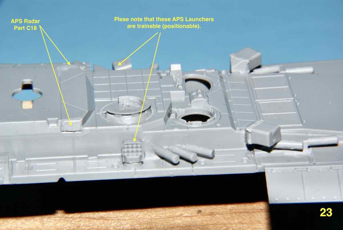
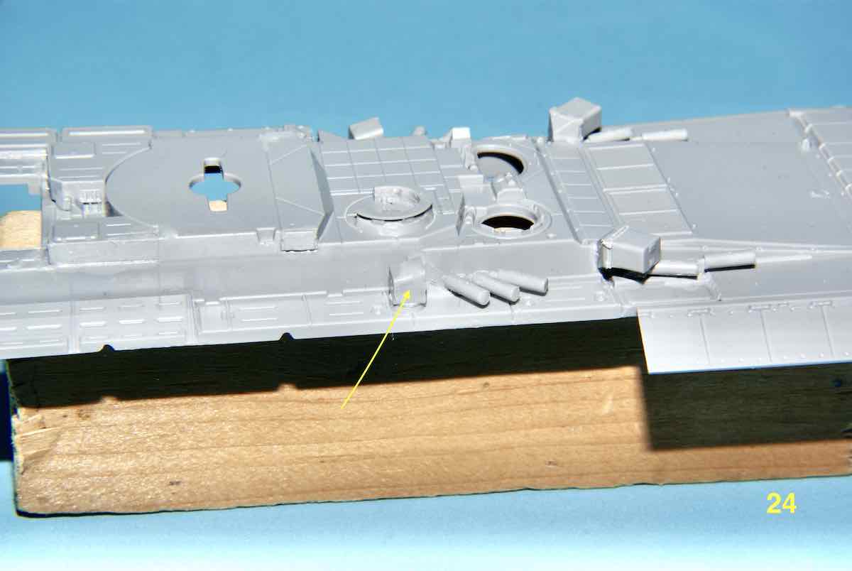
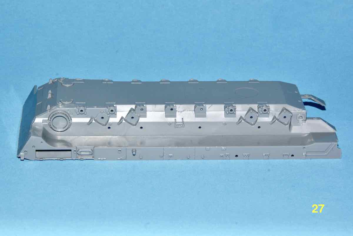
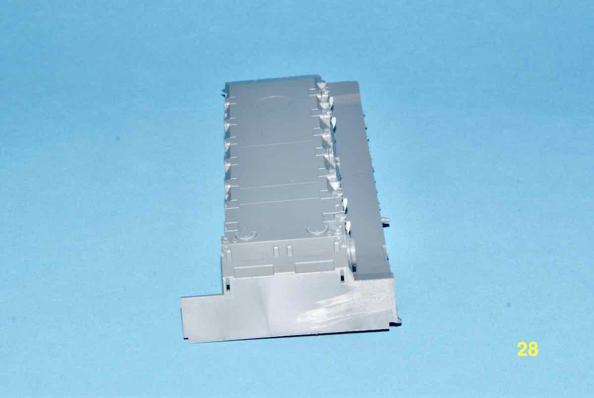
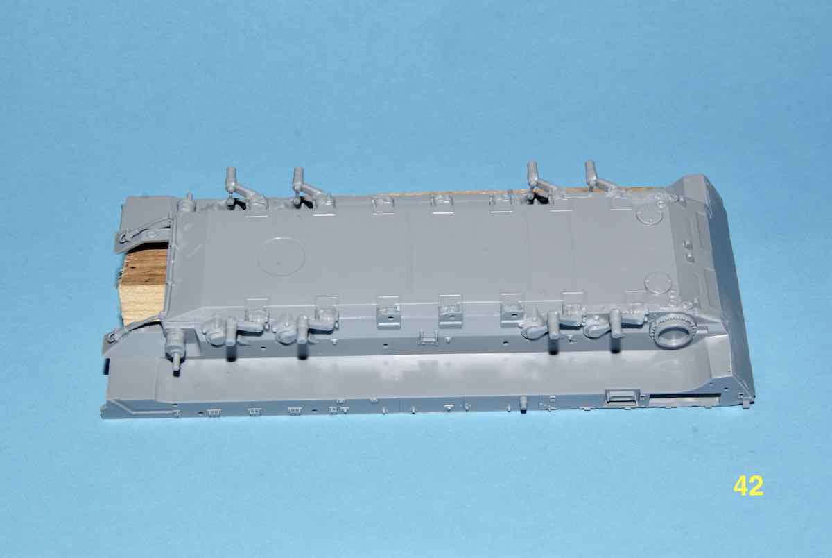
First up are general images of the hull top and the sub-assemblies in place.
Next images are of the side trainable APS launchers. The builder can choose to make them workable but be forewarned, the Part C20 is the underside cap that fits on a pin and has a recess in it to fit over the pins’ end. This cap is only 2 mm wide and .8 mm thick. The recess for the pin in the cap is about .5 mm deep.
As you may notice, the headlights and their bush guards still aren’t installed. I have not yet decided but with STEP 2 pretty much complete I may start STEP 3 shortly. This step is assembling the lower hull of the TBMP. Thats it for this update, if anyone has any thoughts or questions, don’t be shy just ask away? 
Cheers,
Jan 
@tread_geek - Jan,
Is this vehicle capable of traversing over water? It sure looks like it can, I know nothing of these vehicles. Half PT boat half tracked vehicle. These modern Russian vehicles look so interesting.
~ Eddy 
@Braille - Eddy,
In answer to your question, at 50-55 tons the T-15 is about as amphibious as the proverbial solid, lead balloon. However its armour is pretty much equivalent to many modern MBT’s. It was designed to accompany the T-14 MBT into battle not follow it as other APC’s do. Unlike the T-14 the T-15 crew is not housed in a separate armoured capsule up front but in the main crew compartment behind the engine. This compartment also holds a nine man section od infantry besides the crew of three. The Boomerang turret is totally isolated from the interior and has blow-off panels over its ammunition. Hope this brief description gives you a better idea what this beast is all about.
Cheers,
Jan
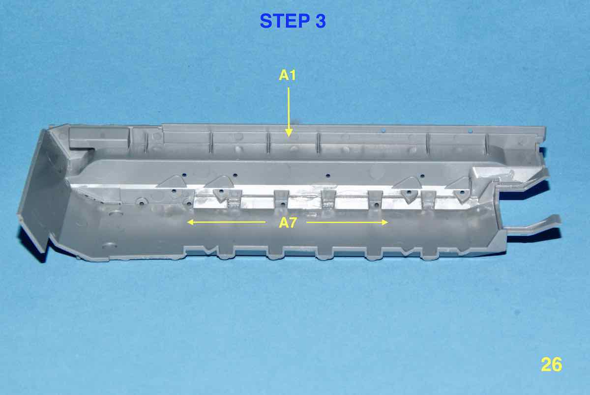
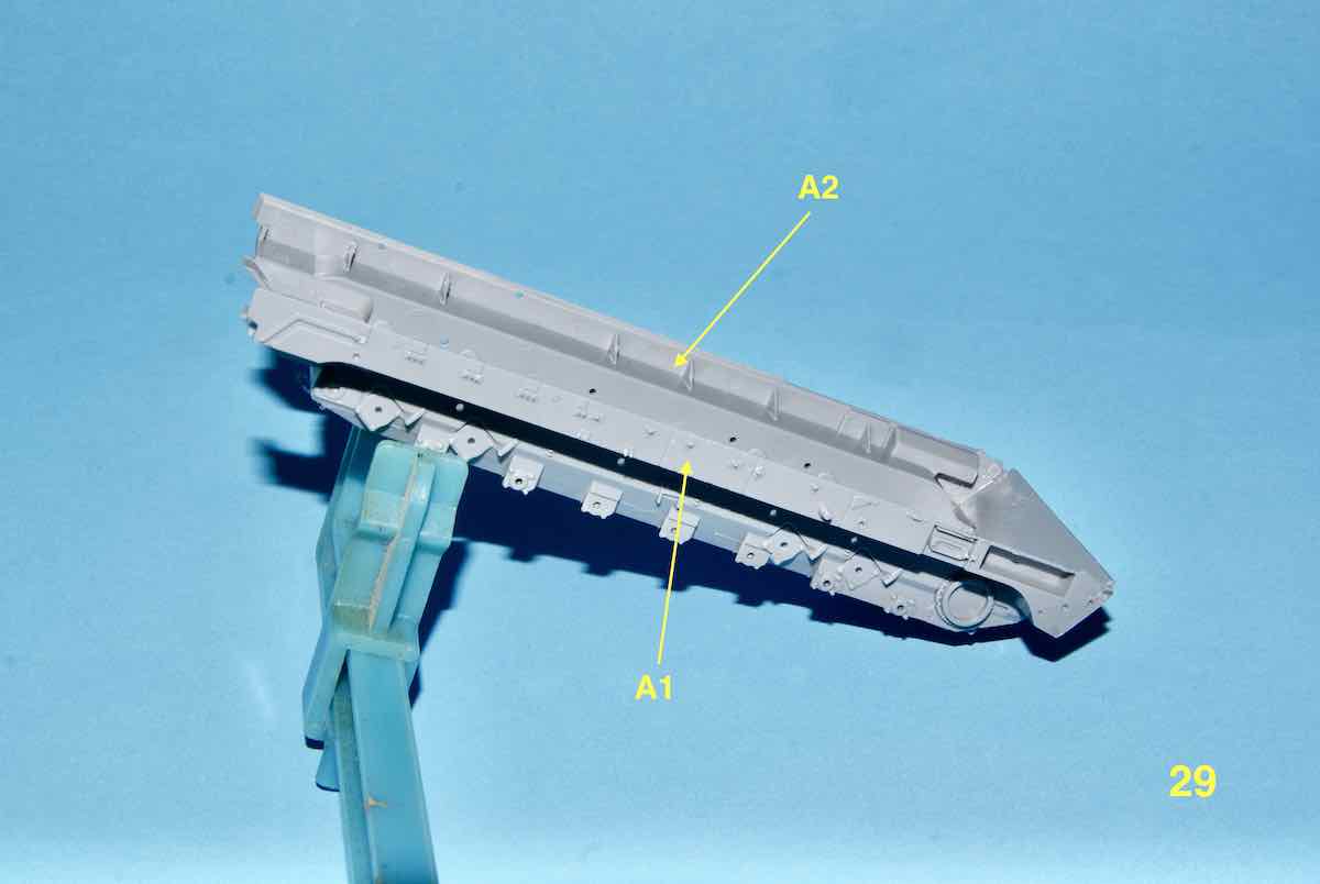
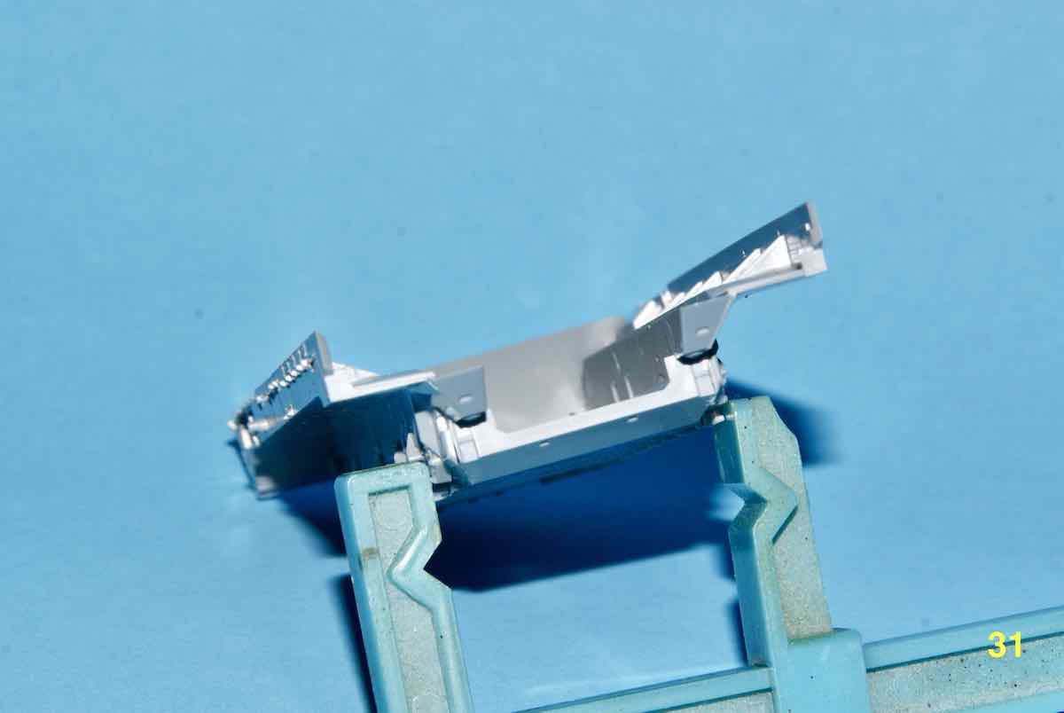
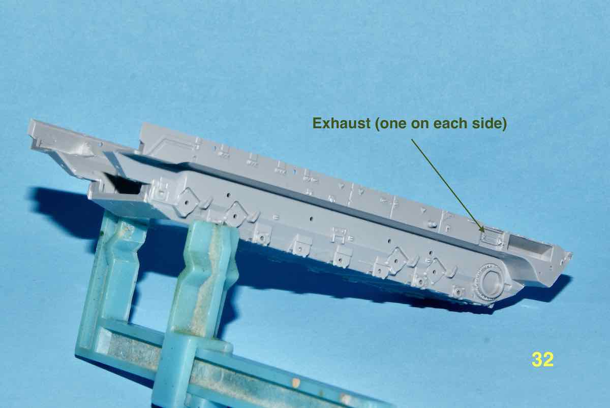
Well surprise, surprise, I started the “simple” STEP 3 but those three parts in that step were not the easiest to align and hold until the glue set. Zvezda uses several alignment tabs to supposedly assist the alignment process. Unfortunately these are long and somewhat thin parts so are subject to some minor warping. Getting things aligned was a process that could have used at least three hands but I was left to use only two so it took a while.  Hopefully the following images with some markup should speak for themselves?
I must admit that image upload is a dream compared to anything I’ve experience in the past (my thanks to Jim Starkweather and all who got this all running )
Cheers,
–Jan
2 Likes
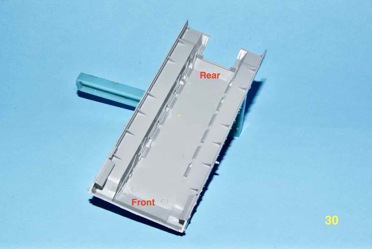
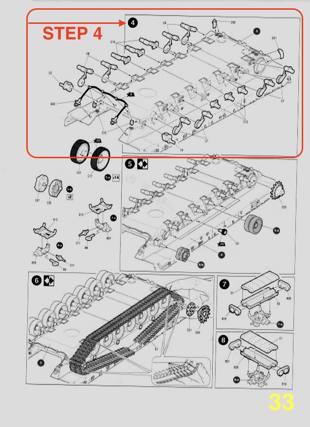
No progress today other than some photo and scan editing and preliminary planning. I am looking at tackling this next step outlined in red in the scan below.
Getting familiar with this new sites’ features and capabilities is a learning experience so I’m trying different things to see how they work. In the old forums my reviews, BLOGs and features all worked according to what was set up for them respectively. So far there is nothing similar with the new version so that’s why the experimenting.
Oh, and add to that new photo editing software that allows image markup.

Cheers,
–Jan
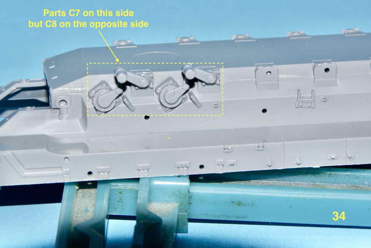
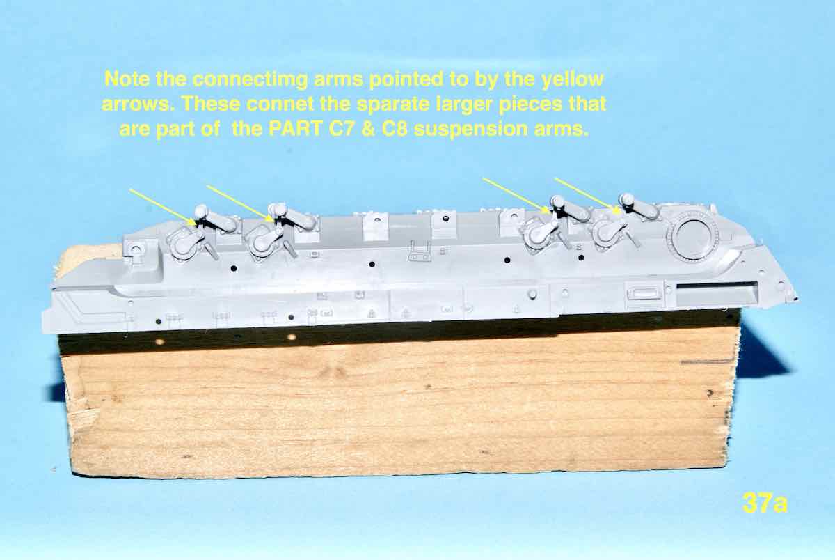
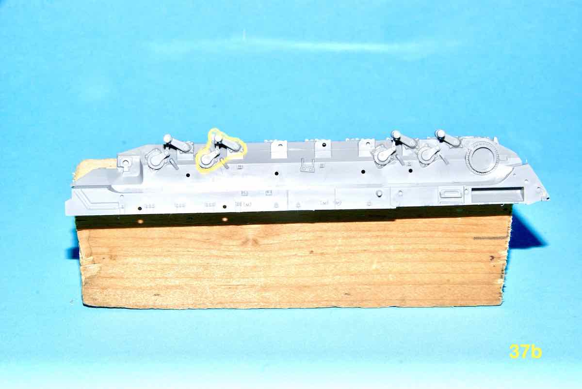
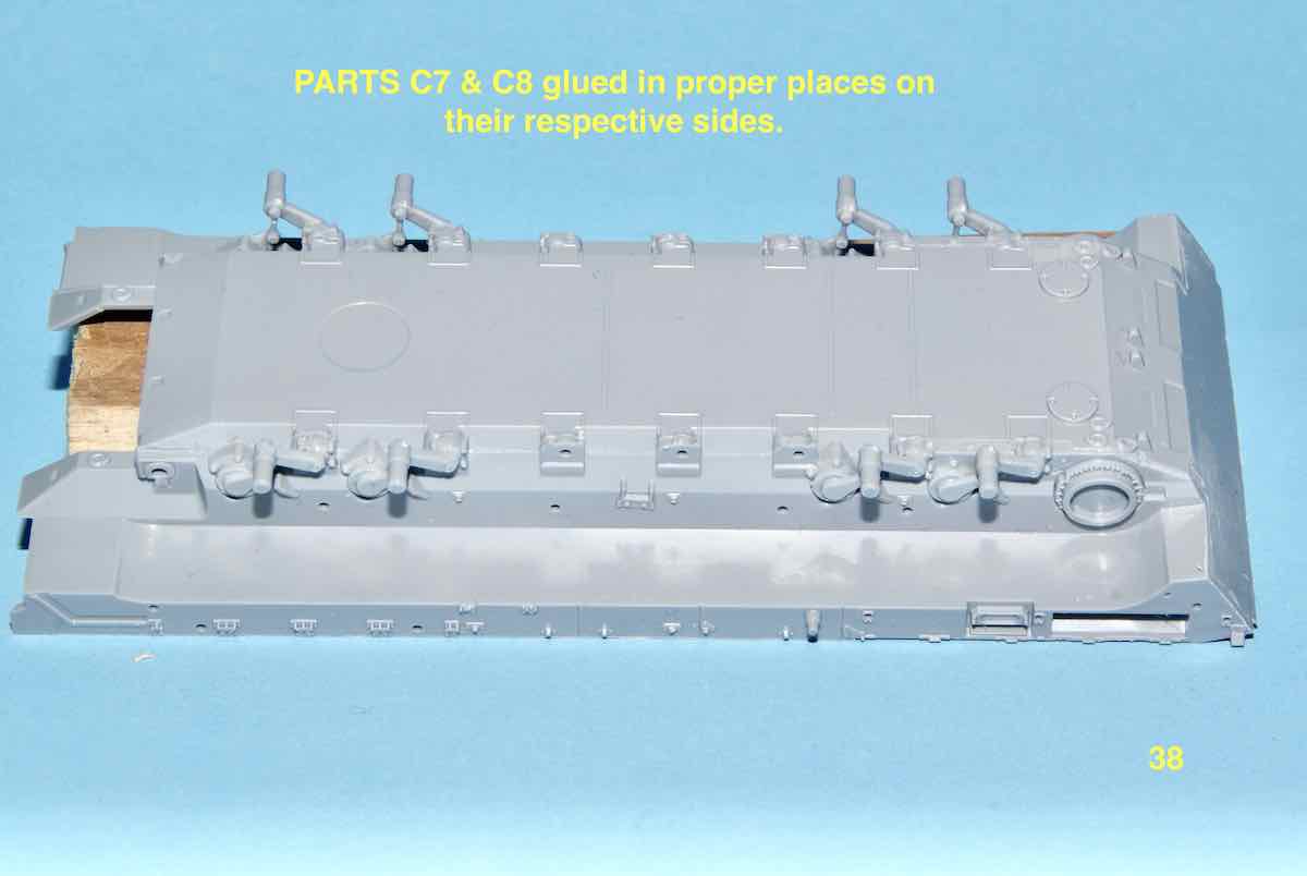
Had a brief time at the workbench today and glue actually met plastic. I started with the left side, rear pair of bogie arms. Warning these arms are all VERY LOCATION SPECIFIC. In this case please follow the instructions because what goes where can get confusing. Also note that parts C7 and C8 are held at three points on the sprue and are delicate and can get easily distorted. Here’s what it looks like so far.
Cheers,
—Jan
1 Like
@tread_geek - Jan,
Your getting a bit of bench time and that equates to fun in my book. There are a lot of suspension parts to clean and I was wondering how you go about keeping all of the axel arms lined up because I can only see the locating hole for the axel. Could the axels be separately positioned for placing the model on an uneven surface? I guess in that case you would need to go for some after market track links if any were to be available?
Been meaning to reply earlier but been busy at work and at home. I’ll be away from work for the Holidays and hopefully will get some bench time myself. My build is now somewhat stalled but that won’t stop me from updating soon.
~ Eddy
Thanks for commenting Eddy and the bench time comes in bits and pieces, nothing too regular. There are a fair number of smaller parts (as in minuscule in some cases) and they take patience and time to clean and place properly. That is providing they don’t go shooting off into astral spaces? 
All the axle arms/suspension components have some sort of alignment feature so they all line up in the proper position. However, for a determined and/or demented mind these could be modified with various degrees of difficulty. In other words, not that easily. As the Zvezda tracks on most of their 1/72 vehicles are one piece affairs, a determined individual could theoretically cut them up to serve almost any purpose. 
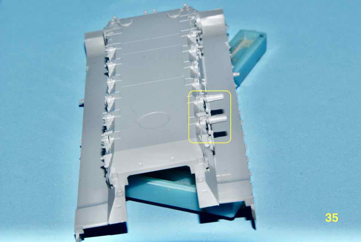
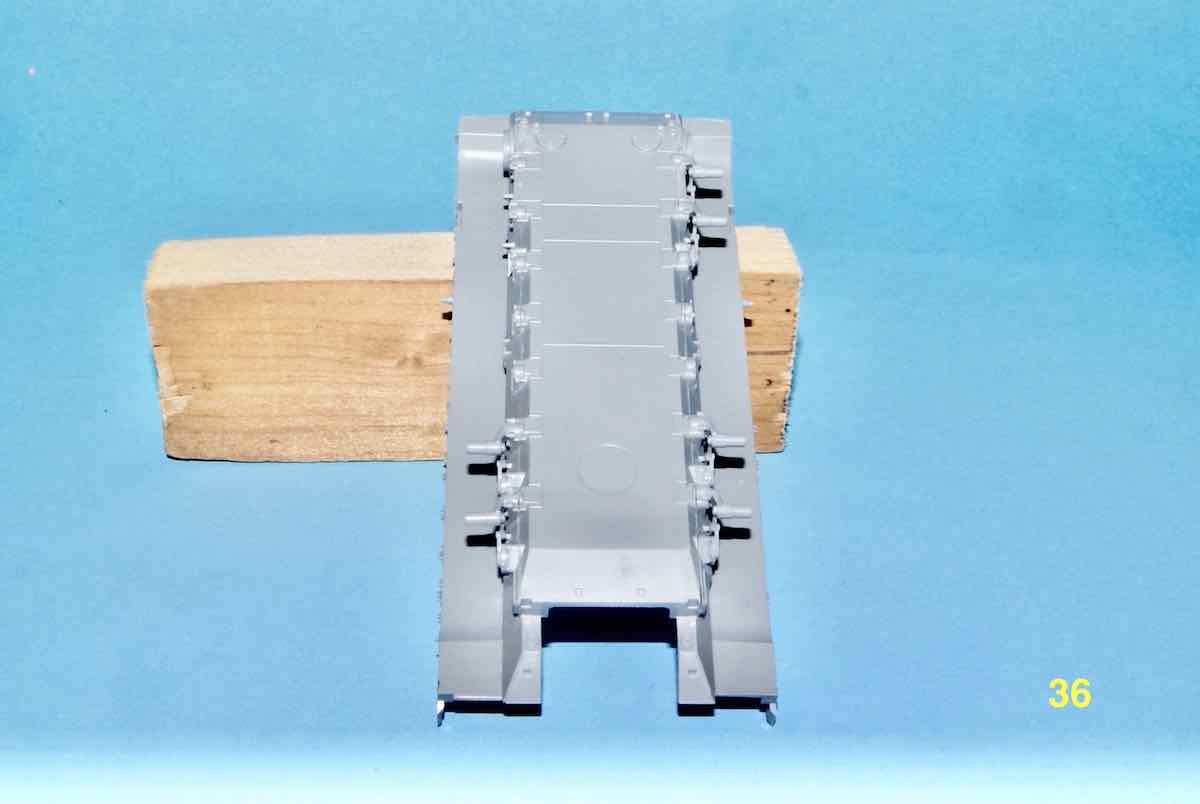
We continue on with the suspension work in this update with further addition of the C7 and C8 components. These represent the axles for the front and rear pairs of road wheels.
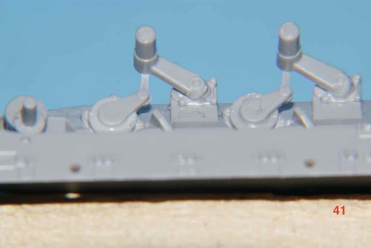
In a following image I have highlighted the Large C7 component to show the form of these parts. Care is needed when removing them from the sprue as the two parts of them are joined by a very thin and fragile arm.
These C7 and C8 parts are modest in size for 1/72 but still quite awkward to hold and manipulate due to their shape.
The next two images are taken using a 4X Macro filter to show the parts in detail. First is the rear mounted tow rope that is made up of three parts, two absolutely minuscule and the actual rope quite fragile.
Next we’ll see a closeup of the idler axle and rear two road wheel axles in place.
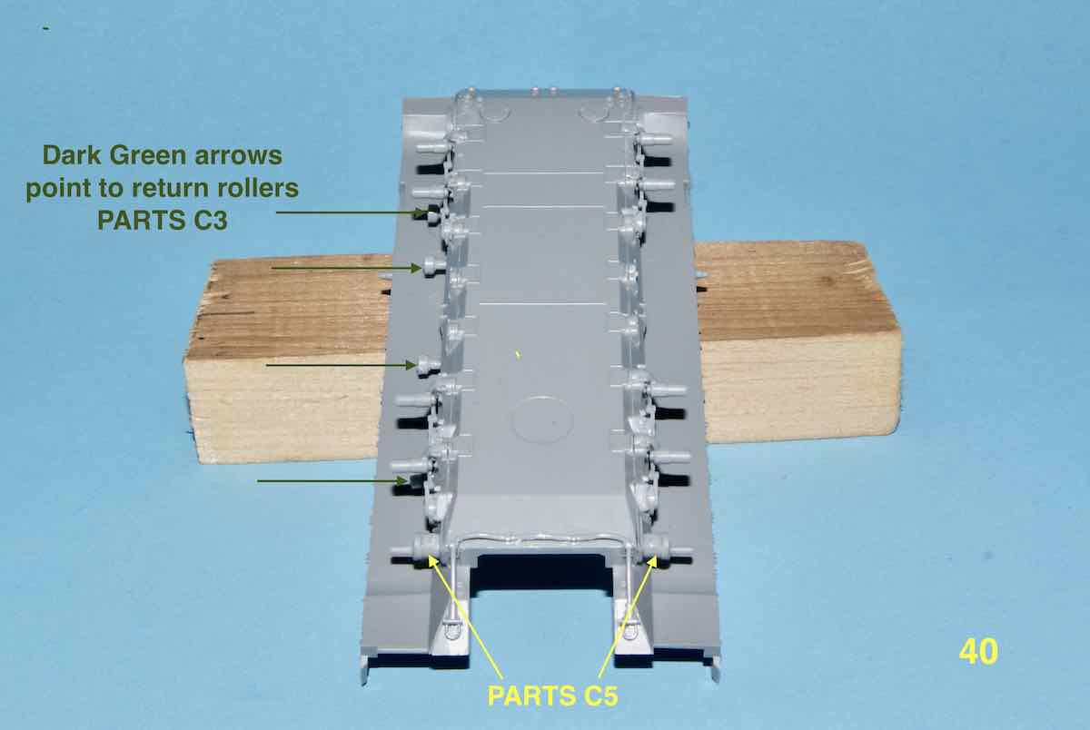
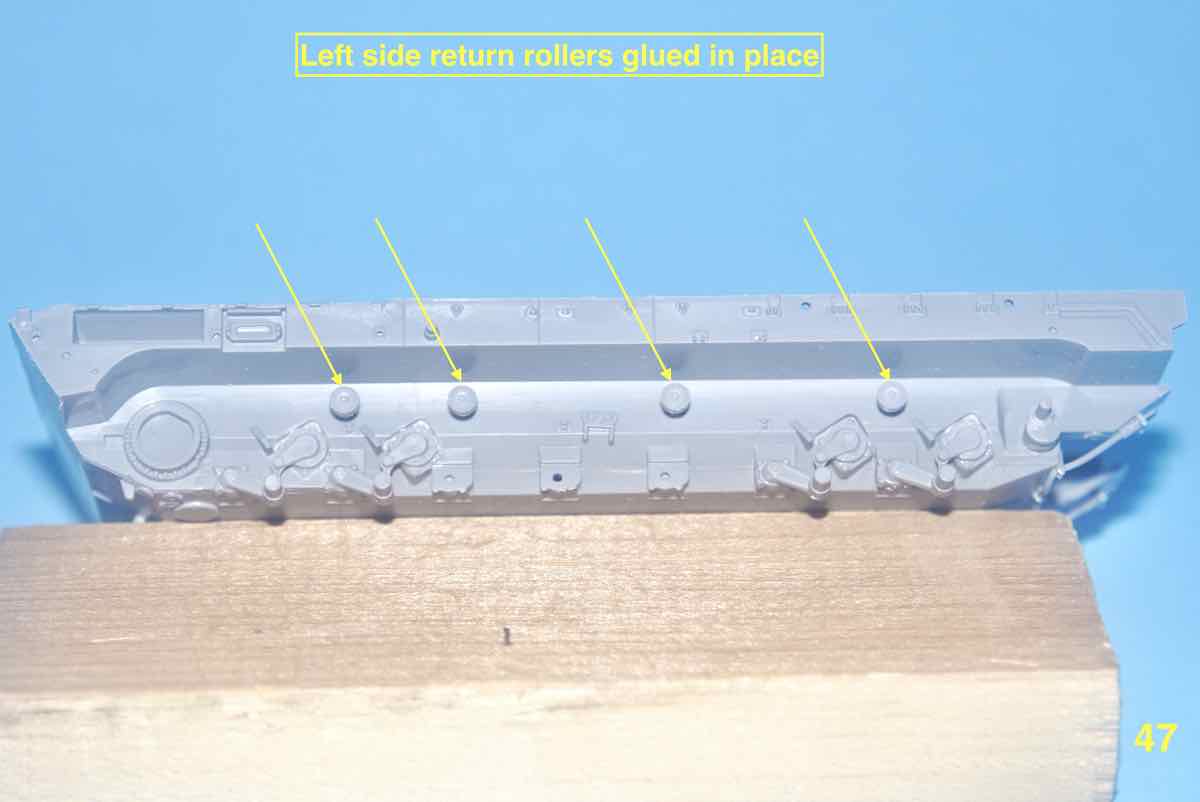
And finally the C7,C8 parts attached with both idler axles, followed by a picture showing the return rollers on one side. Note that these parts are quite small and will require mechanical assistance of some sort to hold and place.
Cheers,
–Jan 
Jan
Wow, those last steps you showed look quite fiddly. Hopefully all that detail can be appreciated once the model is complete.
Sometimes hard to feel like you’re making much progress on stages like these. I find I’ve become very patient (or very slow) in terms of wanting cement to thoroughly set before touching anything else on that same assembly.
Anyway, you’re getting there and this looks like a good kit in terms of detail.
Matthew
Wow, those last steps you showed look quite fiddly. Hopefully all that detail can be appreciated once the model is complete.
Sometimes hard to feel like you’re making much progress on stages like these…
Fiddly, you want fiddly Matthew you’ve come to the right kit? As for progress, as long as something is getting reasonably well completed I’ll be happy. It’s been a fairly long modelling drought for me so reawakening dormant skills has been an objective also. I must admit that this kit is serving that purpose handsomely? 
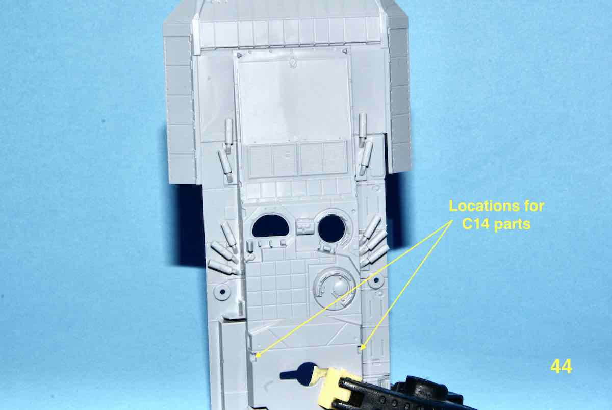
With this update we’ll start by stepping back to STEP 2 for a bit. Two very small parts identified as C14 needed to be placed on the hull top piece. I had removed one of them and while trying to clean it up it “mysteriously” has gone missing at least three times! My cutting mat is located on a tray with raised sides that I hope will catch most if not all dropped, falling or errant pieces. This mat itself is itself located on a workbench that I have covered with a cloth that hopefully would either catch and/or prevent bouncing of any escaping parts. The setup generally works but occasionally the odd part has eluded recapture.
Firstly the instructions for these parts.
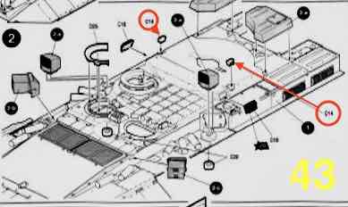
As you can see, even in the instructions the C14’s are small.
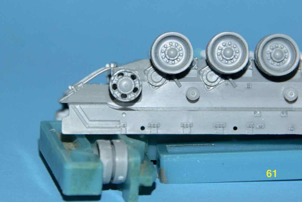
Now where they are to be placed.
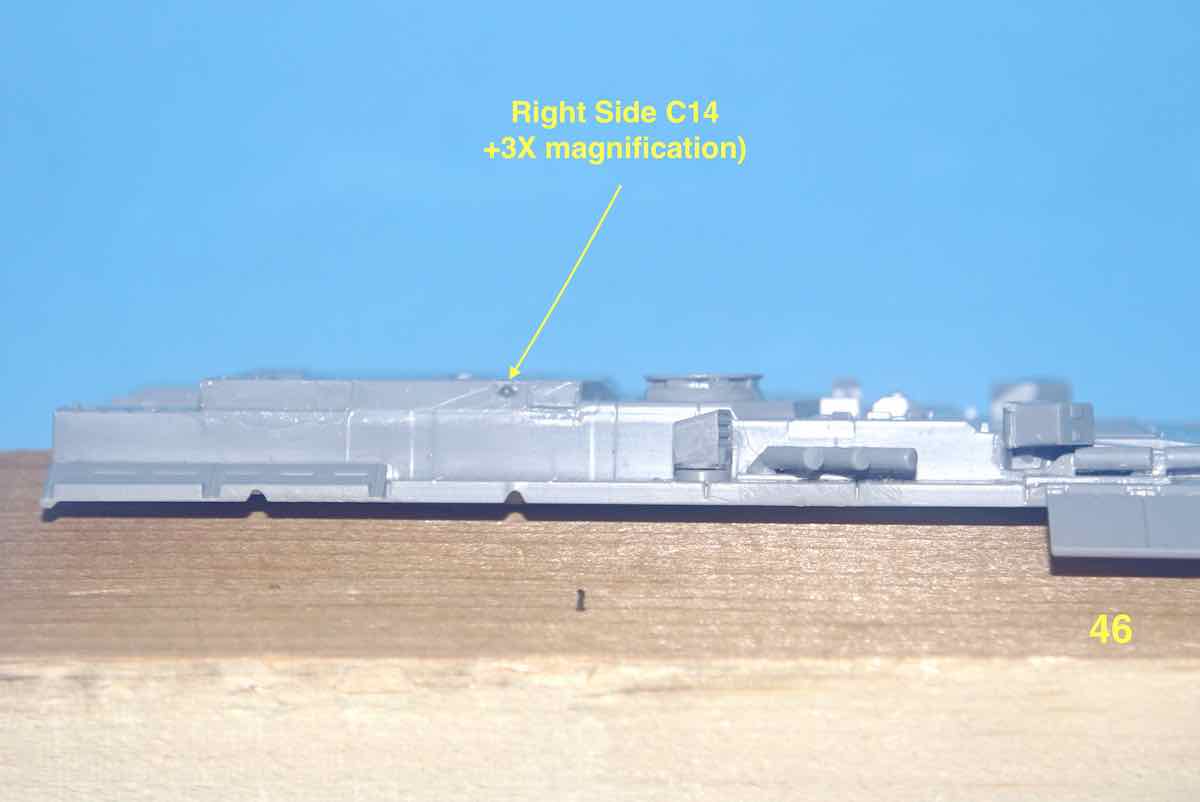
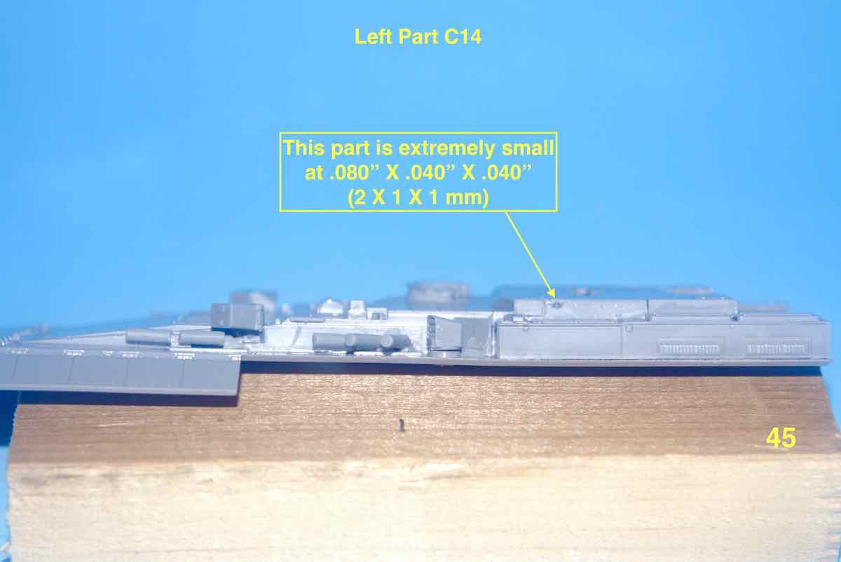
Finally the placement.
As a long time Braille Scale modeller I have amassed a good variety of various sized tweezers over the years. In the case of these super small pieces in this kit I found myself having to resort to bringing out my super fine Micro Set. they made a world of difference in handling these smallest parts.
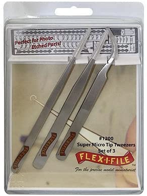
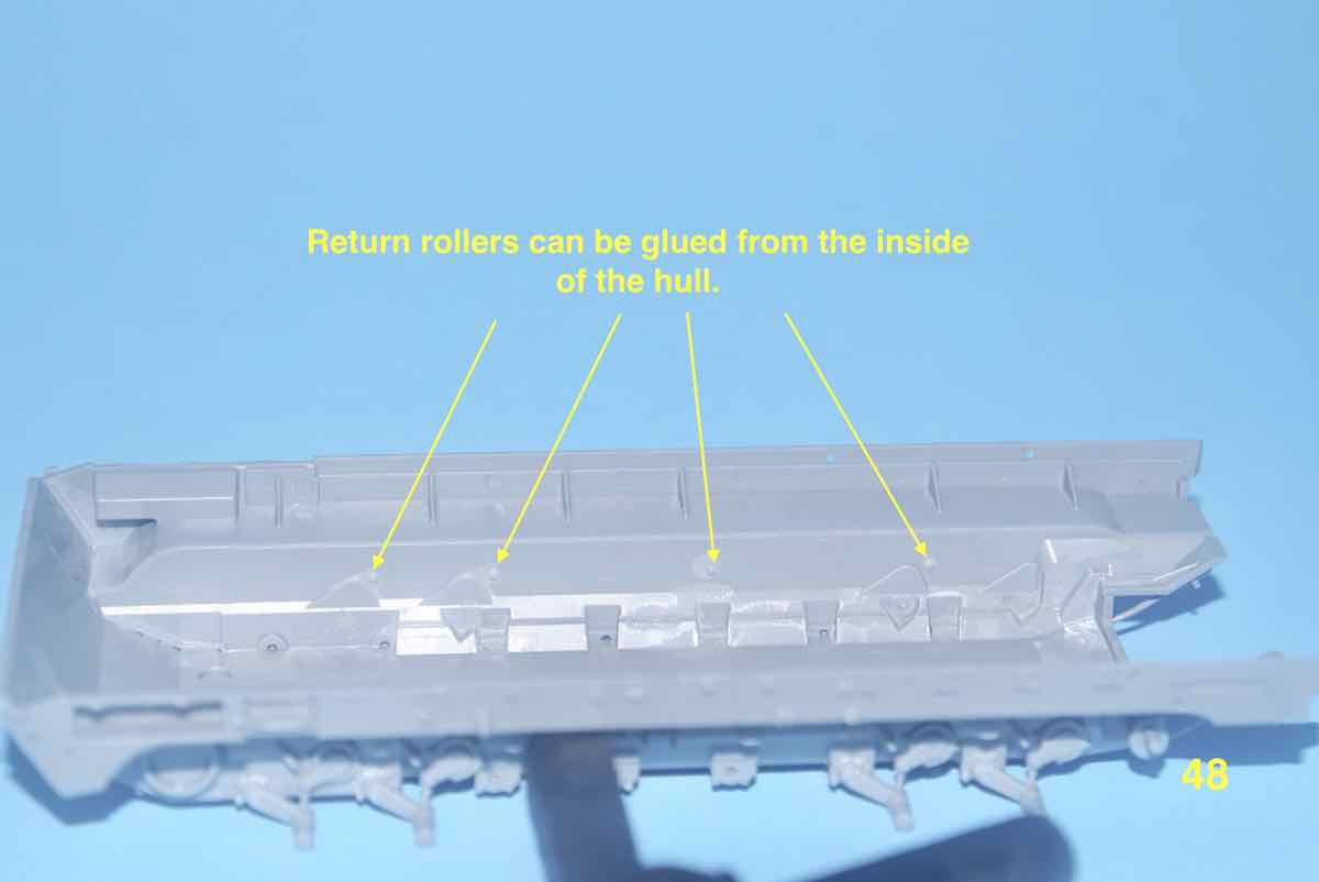
I’ll conclude today with moving back up to STEP 5 and finishing the placement of the left side’s return rollers (aided by the micro tweezers).
That’s it for this update!
Chees,
–Jan
Jan,
Those instructions look very busy with lot of small items to install but I’m sure that after painting it will have been worth the effort in terms of detail. Good idea about the micro tweezers, I’ve just gone and made a purchase of these. I know I will need them as the 72nd stash is quite large.
When I do use my tweezers on the smaller items they tend to over grip the part causing the part to be catapulted to unknow areas in the room never to be found again. So I hope that these smaller sized tweezers will help eliminate this issue? Sausage fingers tend to exhort higher pressures me thinks?
Thanks for sharing this information with all of us!
~ Eddy 
Firstly, Seasons Greetings to one and all! 


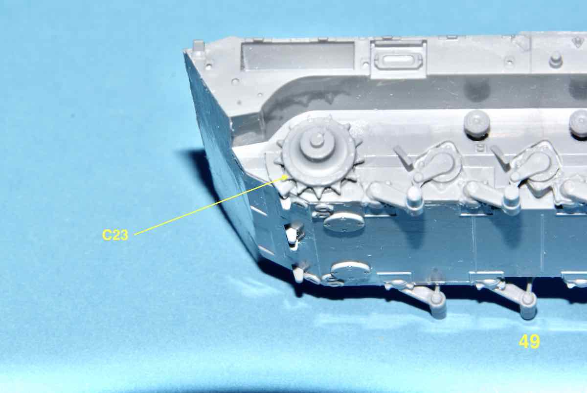
A bit of work on the T-15 done earlier this week. First was placement of the first halves of the drive sprockets. Each sprocket is made up of three parts with the centre and outside shown to be put on in conjunction with track placement. The tracks are the single length with scored bending points.
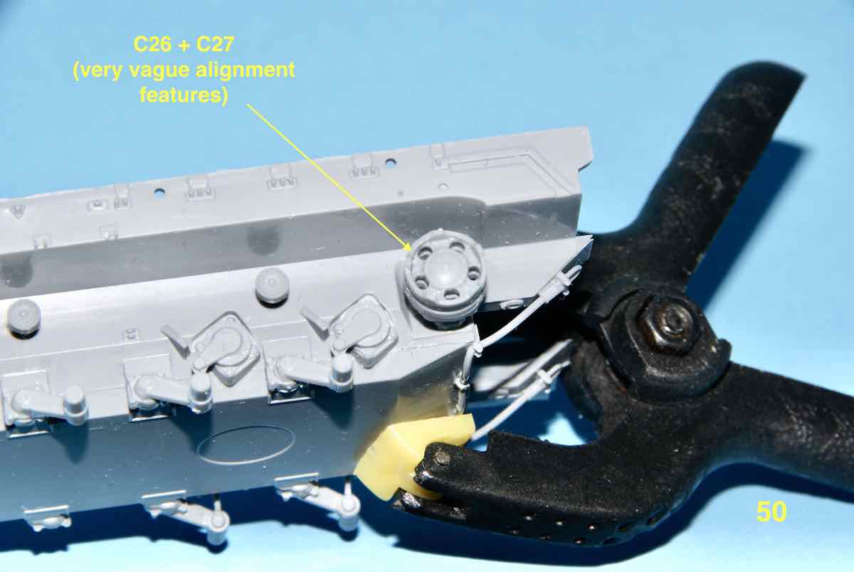
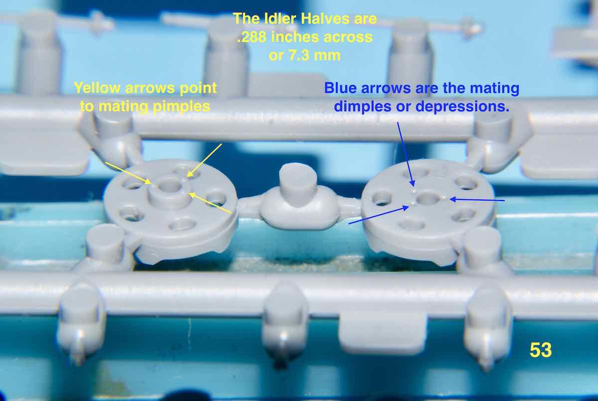
Next is the idler wheel which is made up of two parts that have extremely vague alignment features. These “'features” are basically three microscopic pimples that are meant to fit into three infinitely small depressions. For all intents and purposes, totally useless. Interestingly the instructions show a peg with a key fitting into a hole with a keyway .
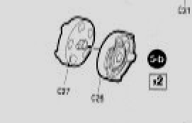
It will be annoying but your best bet may be trying to align these two halves (C26 + C27) by eye.
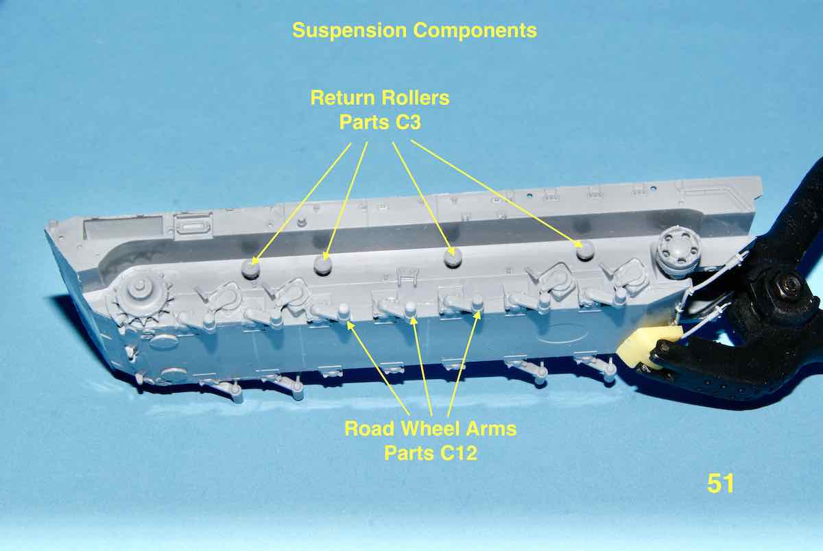
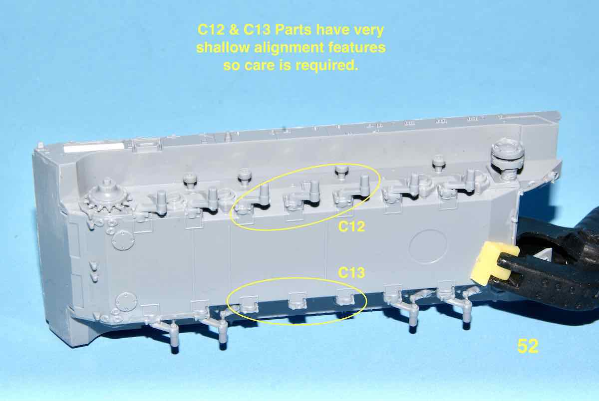
The left side return rollers are now in place and proverd easier to do using the micro tweezers. Then road wheel suspension arms (C12) have quite light alignment ridges. They help somewhat with proper alignment but again the modeller will have to make sure they align well by eye.
This applies to both sides of the three centre arms.
Questions or comments are welcome, have a pleasant day!
Cheers,
–Jan
2 Likes
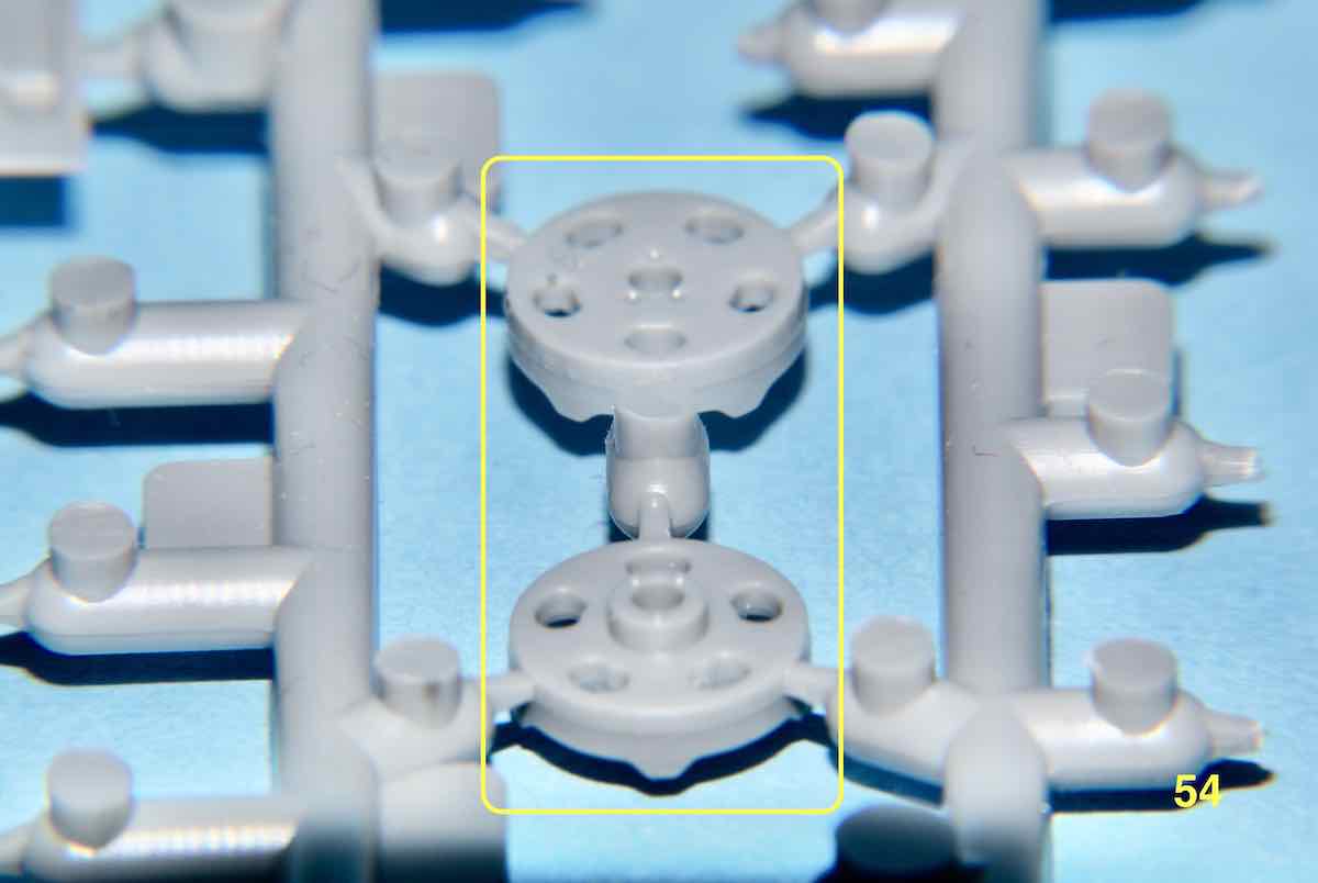
Greetings to all the followers of this thread. No real progress since the last time as I’ve been dwelling over how to properly align the two idler halves. I have taken two 4X magnified images of these parts to show how pathetic the mating features for these two parts are. Hopefully the photos are self-explanatory and show how virtually useless these so called mating features are.
On top of everything else the joined idlers must fit over a peg or shaft and then in turn have the one piece track wrap around them. Hopefully I can devise a jig/fixture to assist in this alignment issue. Thanks for your interest.
Cheers,
– Jan
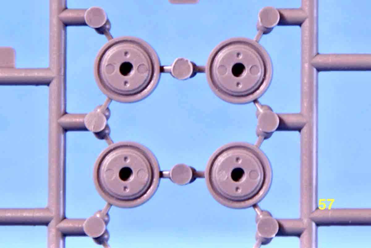
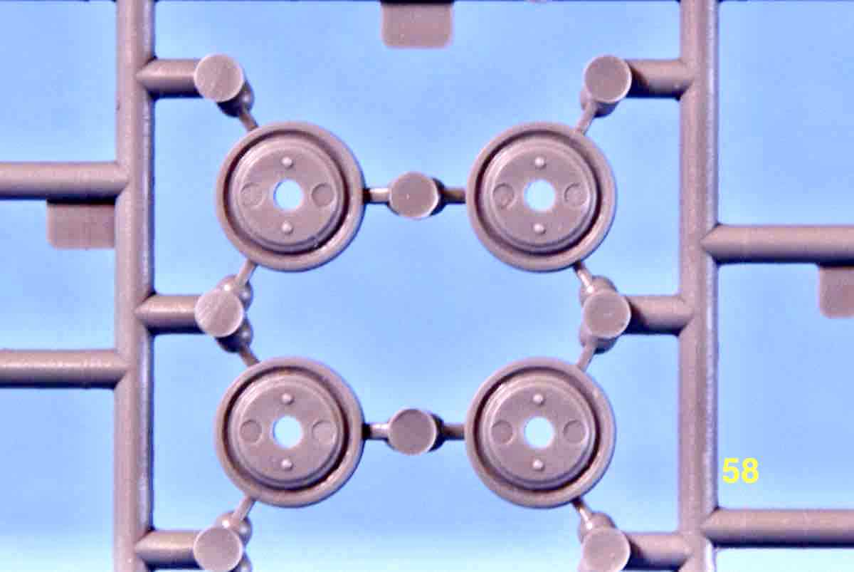
Small update today still pertaining to the suspension. I still haven’t found a solution to the idler wheel assembly but now it’s compounded by the main road wheels. It seems Zvezda repeated using tiny “pimple” and “dimple” locating features for joining the two road wheel halves. The pimples and dimples are somewhat larger than on the idlers but still not solid in their mating feel or alignment. Here’s a couple of images of what I’m writing about.
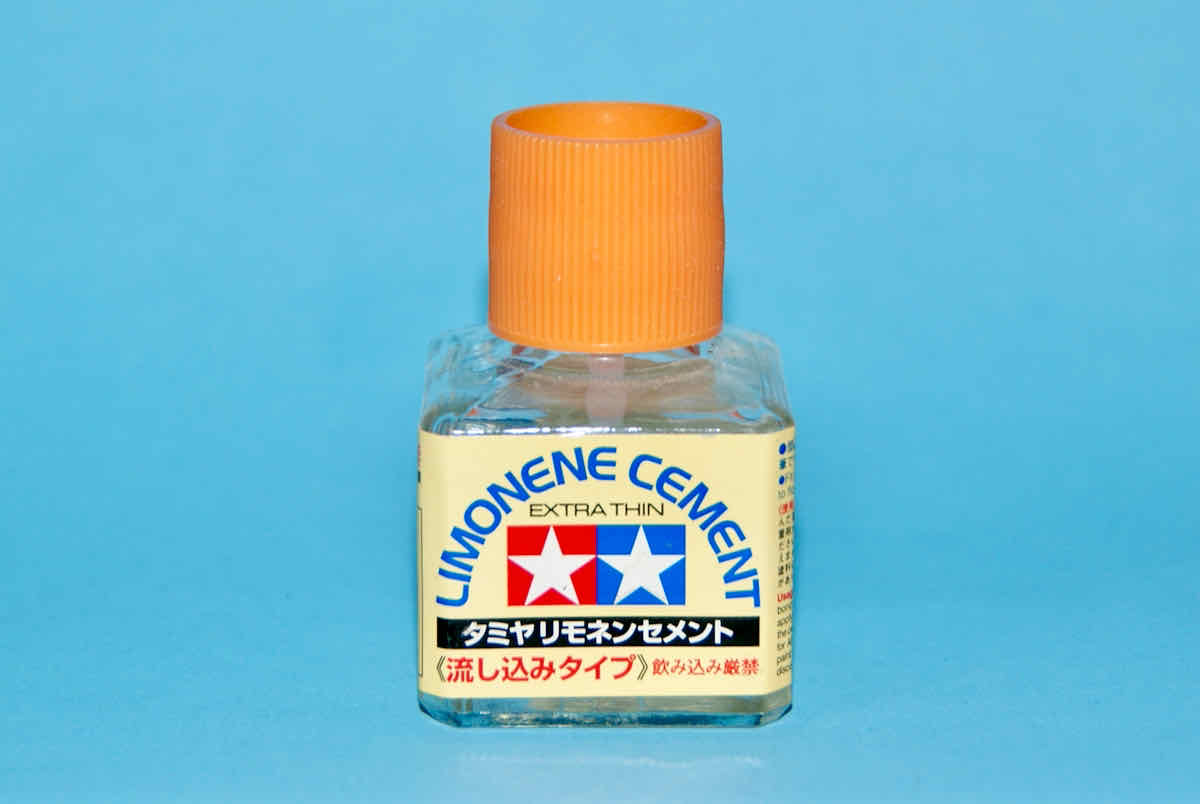
There are fourteen of these road wheel sets required and its been slow going to make sure everything lines up properly. I am using a slower drying Tamiya Limonene Extra Thin cement to give me a longer working time for adjusting parts as needed.
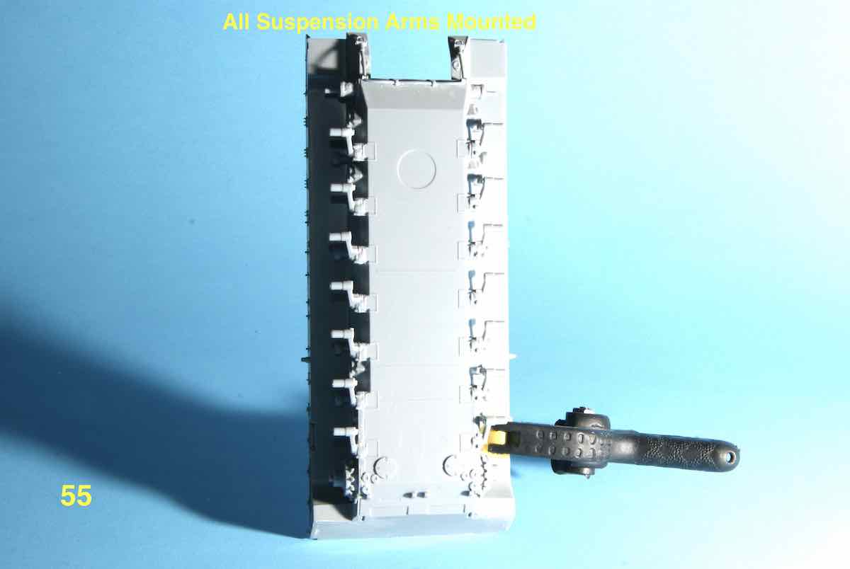
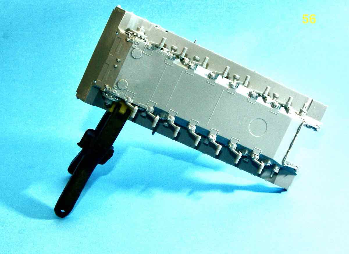
Obviously I have the suspension arms all attached and the three centre arms on each side where a pain to align properly. Here’s then end result.
I have five road wheel pairs assembled and will take pictures shortly.
Cheers,
–Jan
1 Like
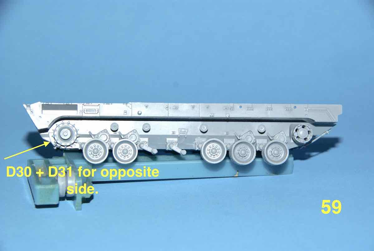
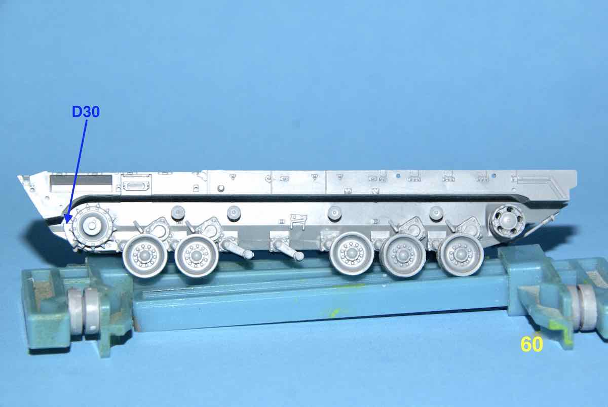
Finally made a very crude jig out of styrene and assembled the idler halves. Unfortunately I didn’t take a picture of the jig and I had to take it apart to remove it from the part. Here are a couple of the images of the one idler glued. The other has a few road wheels dry fit. The D30 and D31 parts are very small and here you can see where they fit.
(EDITED: to add extra picture and correct numbering of images)
Cheers,
—Jan
2 Likes
Jan,
It’s good to see that one of us is making progress on our projects. Yes, it can be tedious work to put together so many wheels but in the end it’s looking good. Thanks for the tip on the Tamiya slow setting liquid cement or is that a glue from a squeeze tube? I’ll have to look into that. The tweezer set has finally arrived but haven’t used them yet, been working on photo-etch fenders and some soldering.
Keep this one going when you can I’m enjoying watching this one coming together. Perhaps you could find a figure in this scale to show just how large this vehicle is?
~ Eddy
@Braille - Eddy,
Thanks for dropping by and having a look and commenting. Unnecessarily tedious is a more appropriate term for this beasts suspension. Especially annoying is the near microscopic so-called alignment features for the road wheels and idler pairs. I’ve assembled Zvezda’s T-90 and its wheels were a breeze to put together.
As far as the glue goes, it actually is a cement and I apologize for not providing an image earlier so here is one.
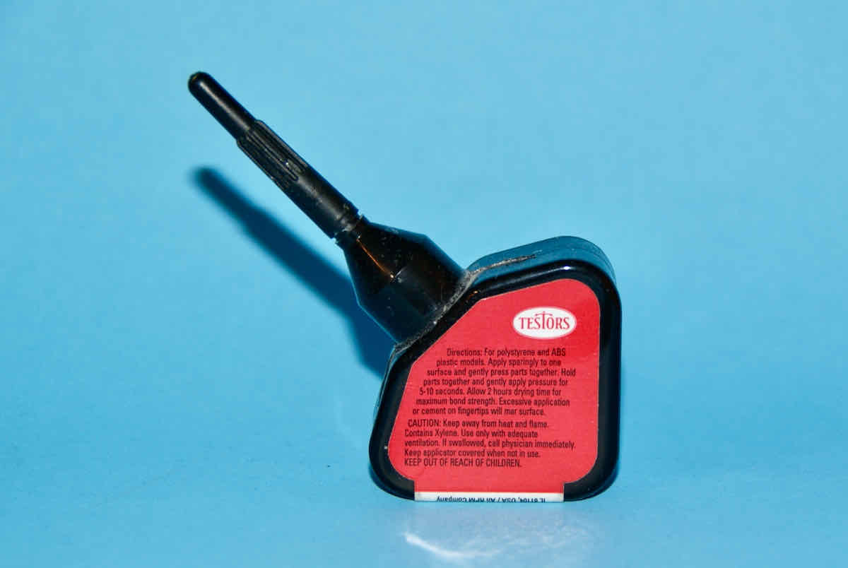
Please note that it is NOT as thick as a “tube glue” but quite thin and it will get tacky fairly quickly. In place of “tube glue” I have taken to using the following Testor’s product. It is a similar gel-like quality like the tube kind and possesses similar attributes.
As with most tools you’ll need to experiment a bit to find what will work for what case.
As for the tweezer set, I actually had them sitting in my tool box for quite a while before finally breaking them out for this build. Boy was I sorry I waited so long to see how useful they can be.
I’ll have another update shortly but I need to prepare a few pictures first. Thanks again for commenting.
Cheers,
–Jan
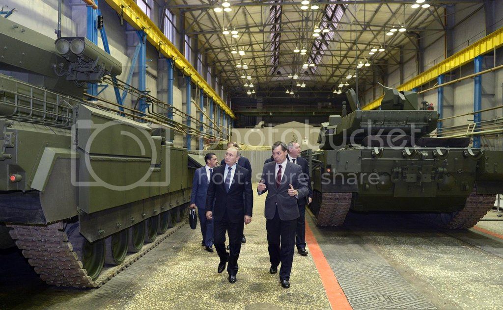
Sorry that I didn’t reply to this query but I’ve been struggling with these wheel issue which are the focus of STEP 5 and I’d need to be past STEP 9 before I could even place the upper hull on the lower part. I’ll definitely keep that idea in mind for some pictures as soon as I can. However, here is an image from LeoCmdr’s larger scale BLOG that may give a size idea.
Hopefully I should be back with an update in a day or two. I’m currently in the process of migrating to a new household computer server and that process has demanded my attention. 
Cheers,
–Jan
1 Like
@tread_geek- Jan,
Thanks for the reply it is much appreciated. I have seen this bottle of cement at my LHS but just did not pay attention to what is was for other than just another glue, will have to add this one to the bench. I like using Testors liquid cement too and also use their gel like liquid cement that you picture in the black container.
Now that you have provided all of us a picture of President Putin, and a small entourage by this vehicle we can see that it’s overly huge. Much success with the new server. I haven’t been doing much modeling in a couple of days, busy following update on what’s happening in American politics.
~ Eddy

 Your comments and explanation on the tweezer-pult principle were right on the mark. Perhaps it’s the reality that we don’t appreciate the strength our fingers can exert on tweezers. Perhaps a good example of the physics laws about force, mass and acceleration of small parts?