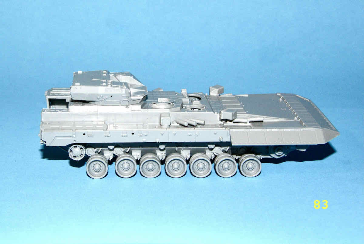
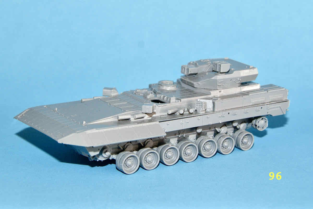
Yes indeed the T-15 does appear gargantuan when compared to the old BMP’s and their rather squat tank brethren of Soviet origin.
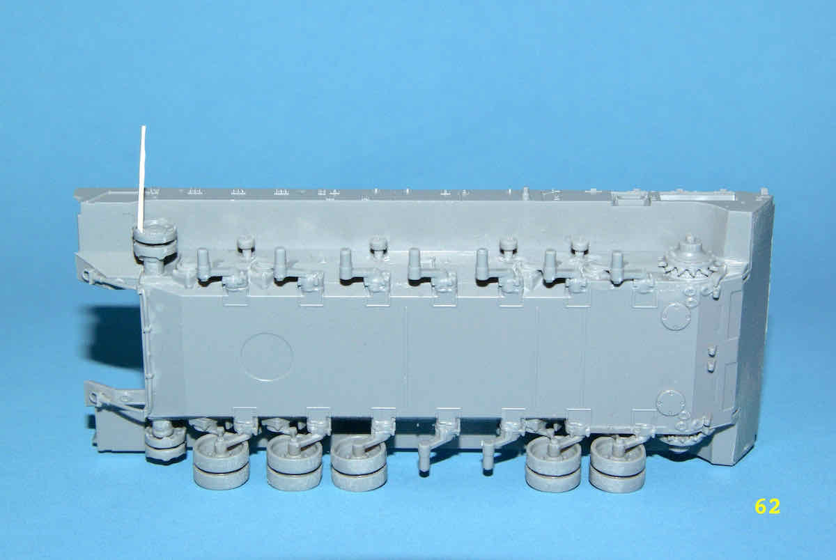
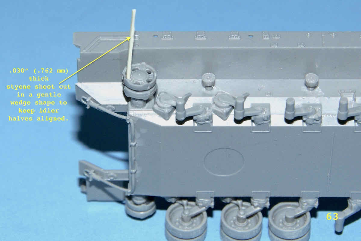
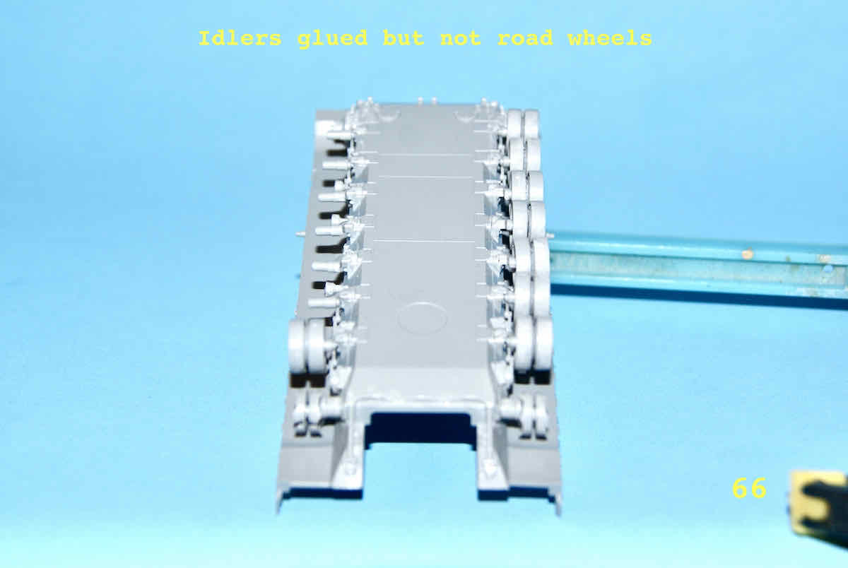
Now for another update. Because of the rather pathetic method of mating the idler halves I created a rather complicated jig to hold the first two parts together while they were glued and attached to their axle. It wasn’t the best and had to be “disassembled” to be removed. I didn’t want to go through all that work again for the other side so I tried to devise a new simpler method to keep the two parts aligned. I came up with using a slightly tapered piece of .030" (.762 mm) thick styrene sheet material tapered so that the thicker part was slightly larger than the holes in the idlers. The inside idler piece was put on this shaft and stopped where the plastic became wider than the idler’s hole. The outside idler was slid down the shaft so that the idler’s tiny mating features met and then this assembly was placed on the axle and glued. The shaft was then removed from the holes after tweezers were used to make sure the idler halves were properly seated against one another.
Here are a couple of pictures of the assembly positioned on the axle.
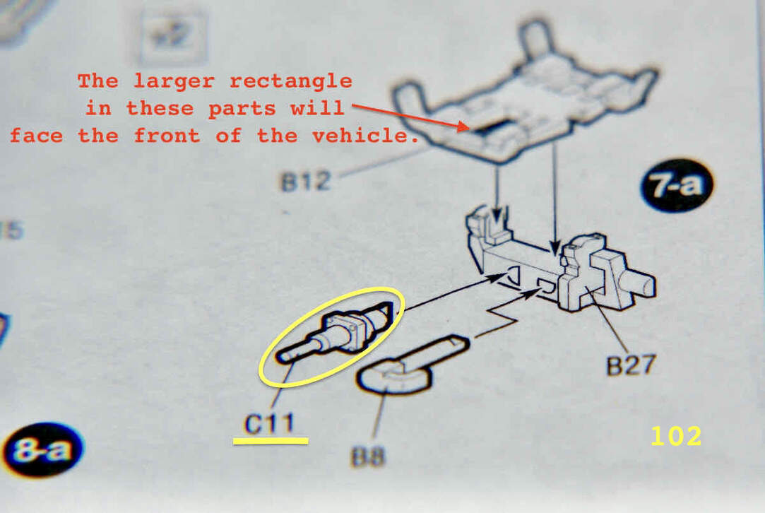
Greetings to all those following this thread. I’ve taken a slight break from the boredom or monotony of doing road wheels. Part of STEP 5 is construction the cradles on which the two pairs of ATGM tubes are mounted. The construction is listed as subassembly 7a and involves four rather small parts. Here’s the illustration:
It turns out that perhaps this wasn’t all that much of a break as it took me a good 45 minutes to find and use the proper sized tweezers to finally get the half moon shaped peg on the bottom of part C11 into its corresponding hole in B27.
I found I had to use a pair of my Micro Tip Tweezers and a lot of patience to mount the part. I have tried to quickly follow this with mounting part B8 but after dropping the part a few times decided to wait until I was more relaxed and ready for the task.
Cheers,
–Jan
UPDATE Three hours after I wrote this update I FINALLY succeeded in installing PART B8!
Finally a bit of an update on getting the B8 part installed after having dropped it no less than a half dozen times. Note, I used the Micro Tip Tweezers to handle these tiny parts. One thing I noticed is that the half-moon pegs do not easily fit into the respective half-moon shaped holes. I have tried sanding down the pegs to assist in this process but it didn’t totally help. What does appear to have worked is placing a bit of Tamiya Extra Thin cement on the parts’ pegs to soften up the plastic. This allowed the pegs to slide into their respective holes without needing too much force/pressure.
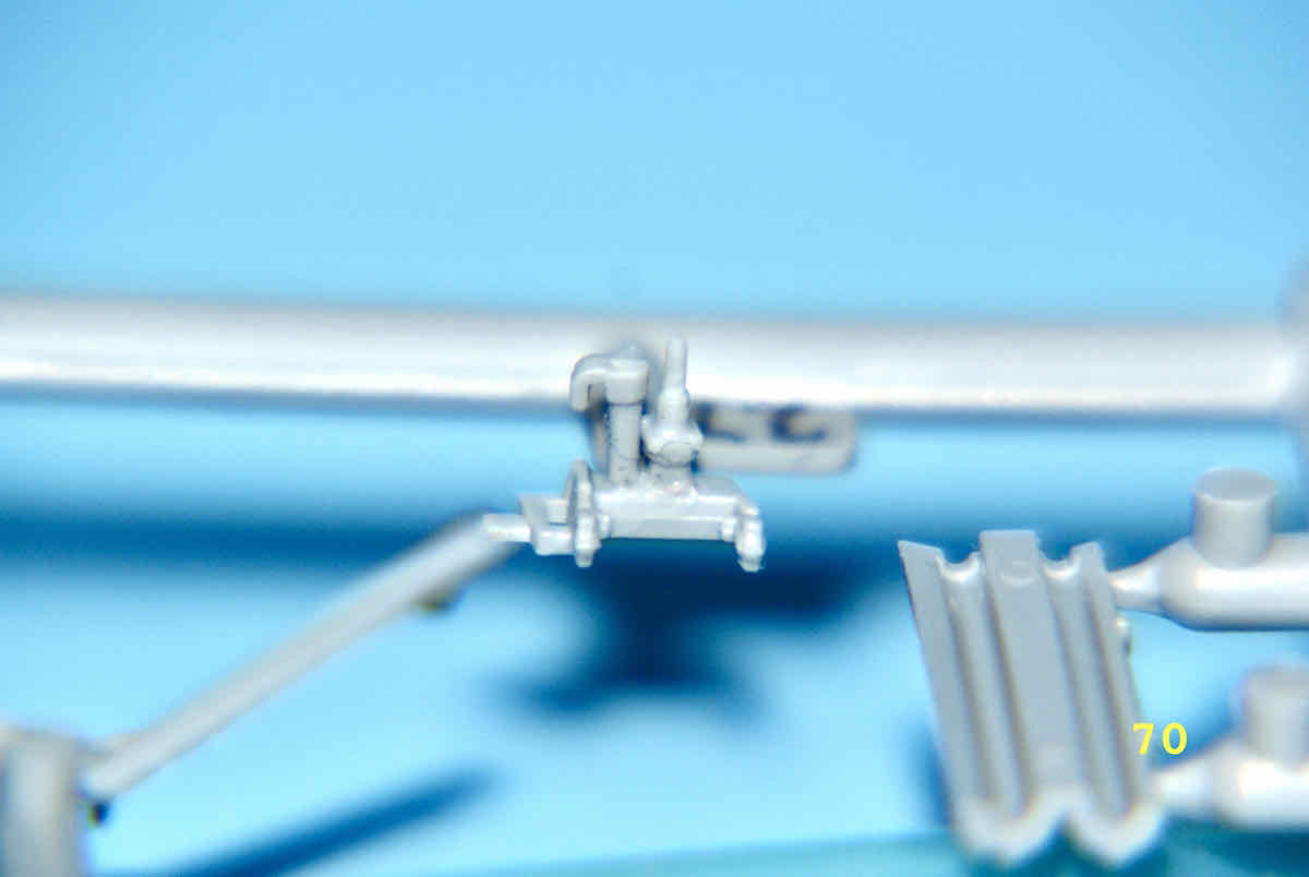
Here are a couple of images of the completed sub-assembly:
I’ve also completed a few more pages of road wheel pairs and been preparing other parts for the ATGM launch tubes. I’d just like to mention here that the instructions are not the clearest in this process and the builder should try to study the parts placement positioning carefully.
Thank you for dropping by, having a look and commenting. As it so happens, I have a 1/72 Zvezda T-14 next in line to follow this build. I can say that since the T-14 and T-15 are part of the Armata vehicle family there definitely are similarities especially when it comes to the suspension. Unfortunately these similarities also involve the sloppy locating features of the idler and road wheel pairs. The nicest thing about the T-14 is the turret and lower hull body at least have slide-moulding and therefore you won’t need to worry about getting sides, bottom and front and back perfectly aligned. A small issue I see however is that since the hull bottom includes the fenders, getting the return rollers in place will be an issue for those with stubby fingers.
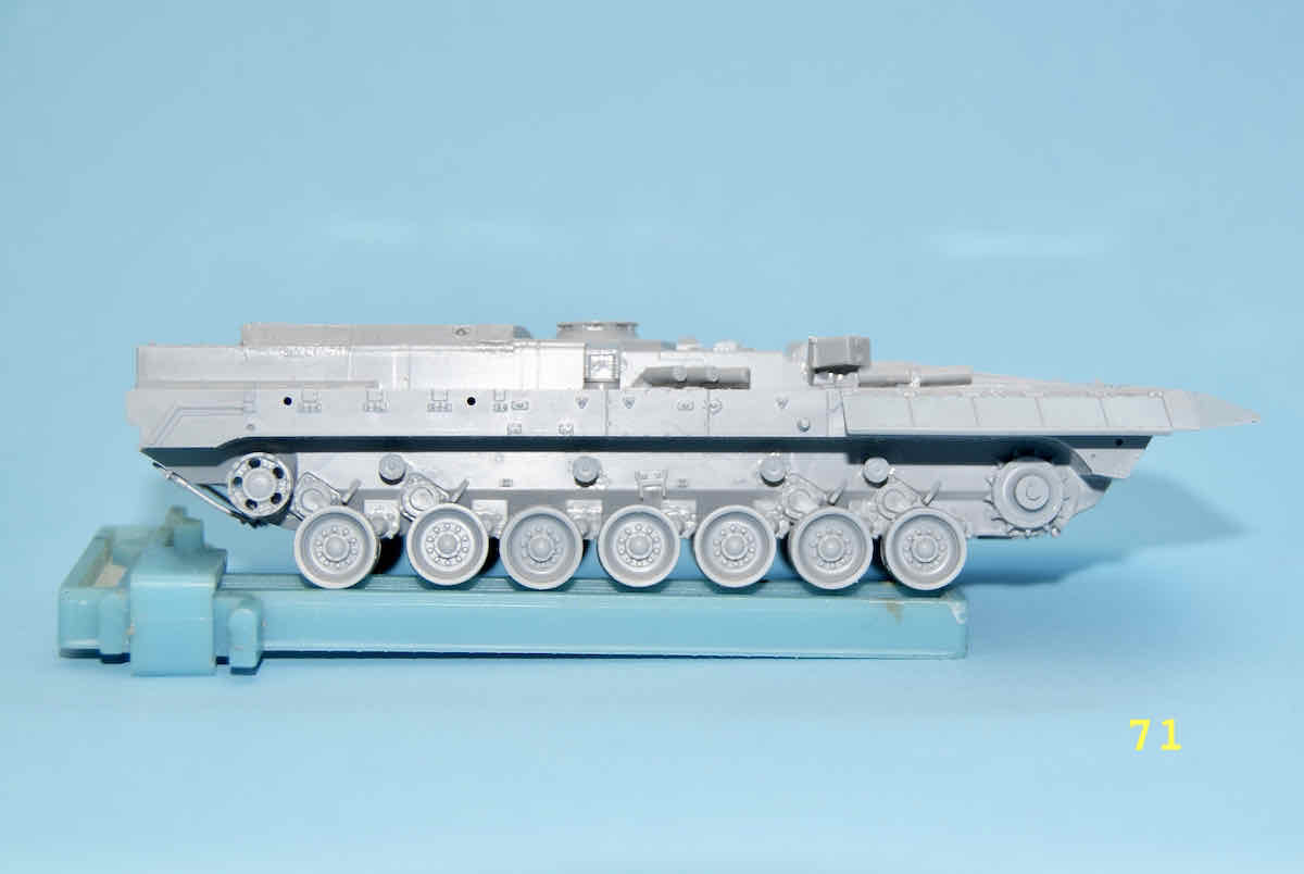
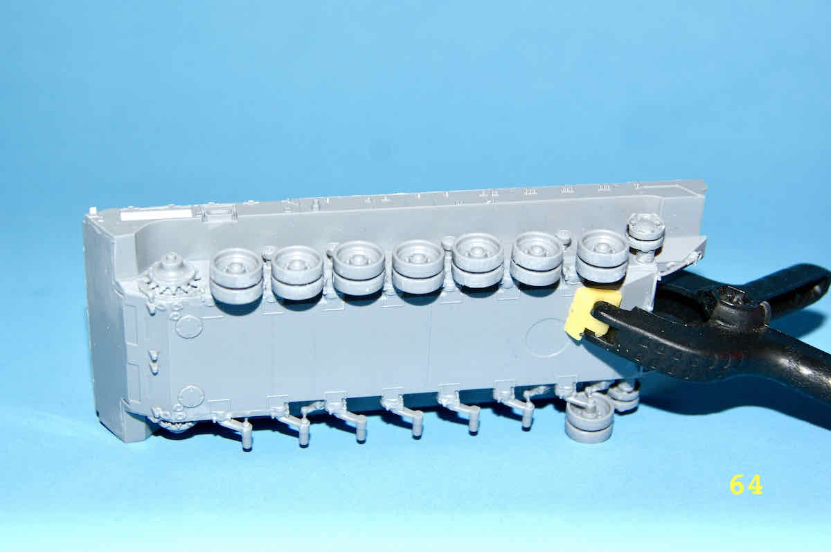
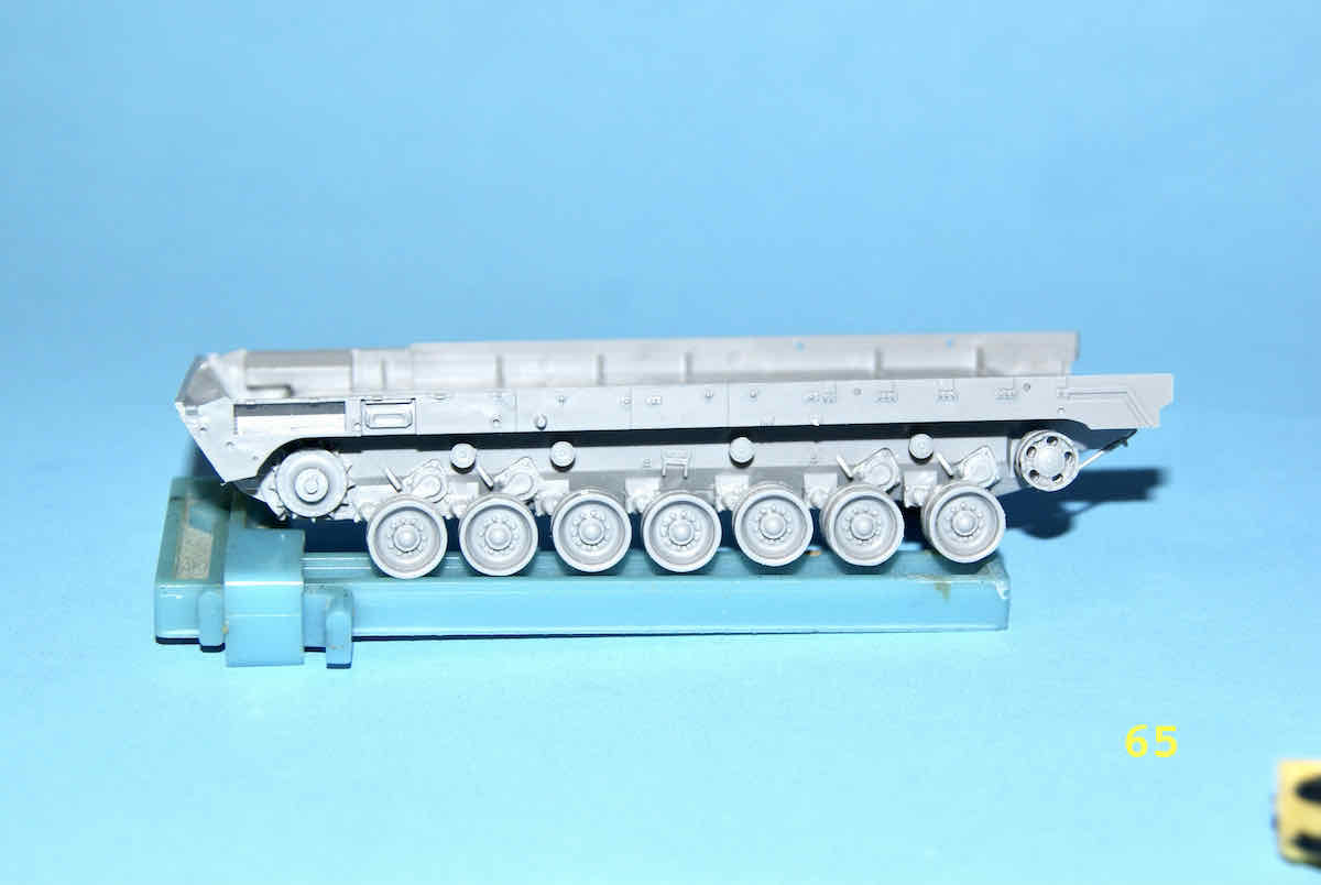
Slogging away the last few days on the last pairs of road wheels and they are finally complete. It was a tough battle but I showed no mercy? I had used Limoneme cement as its slower drying time gives you more working time to align those microscopic pimples with their corresponding dimples. I was only required to disassemble (rip apart) one pair to be reassembled. On with the pictures.
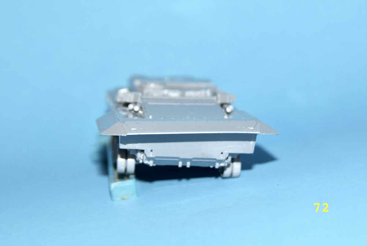
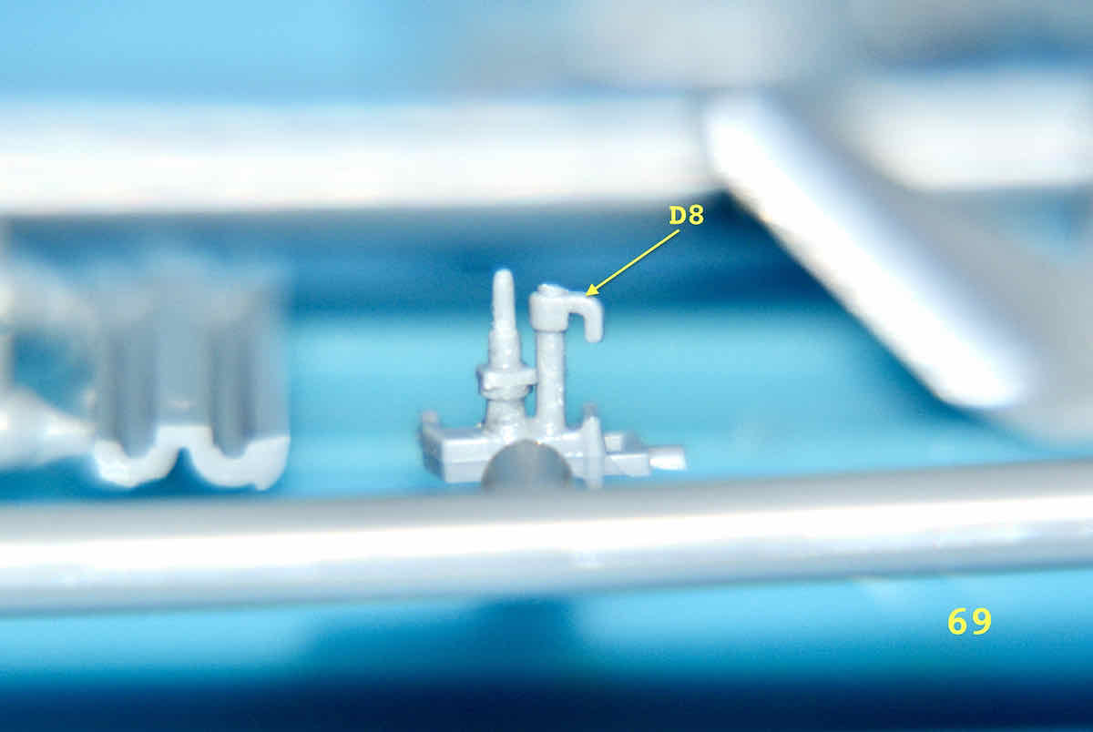
Minor progress update but quite revealing about Zvezda’s accuracy in this kit. I glued the two body end panels A8 and D8 to the upper body part A17 and they fit perfectly. Not only that but they also mated with the lower hull quite precisely. While the hull top is made up of one piece the, hull bottom or tub is made up of three pieces but the hull rear will be about a dozen parts. So far with the exception of the road wheel and idler halves these multiple body parts have exhibited a precision that I have rarely seen and on them Zvezda must be commended. Here are a couple of images with the new parts installed.
The two parts I added were added to the hull top but in a build by a fellow modeller Drewe Manton he added them to the hull tub. For those interested you can find his build here:
[- YouTube]
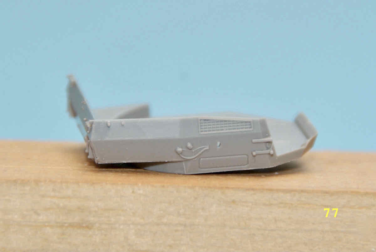
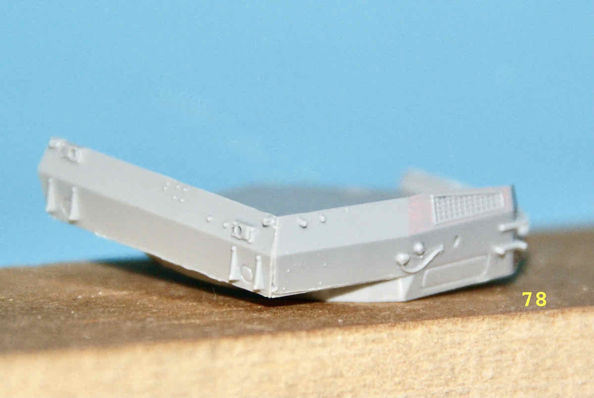
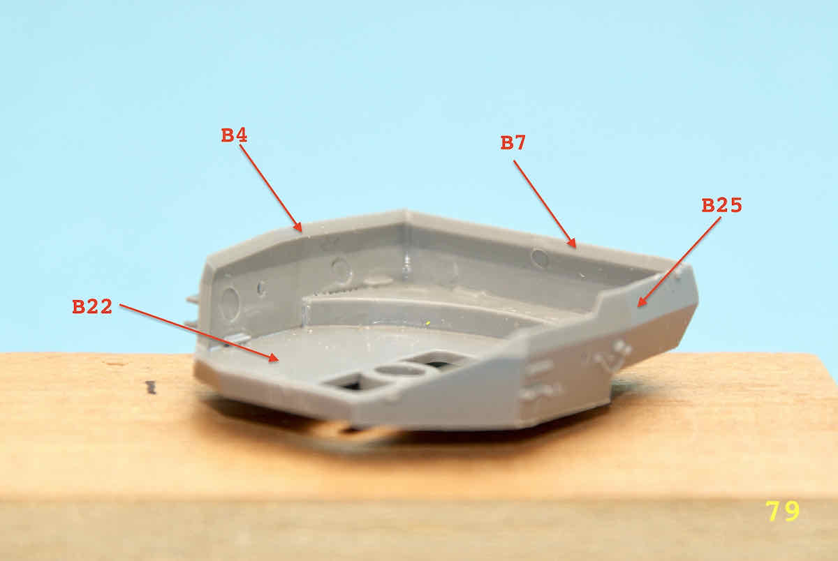
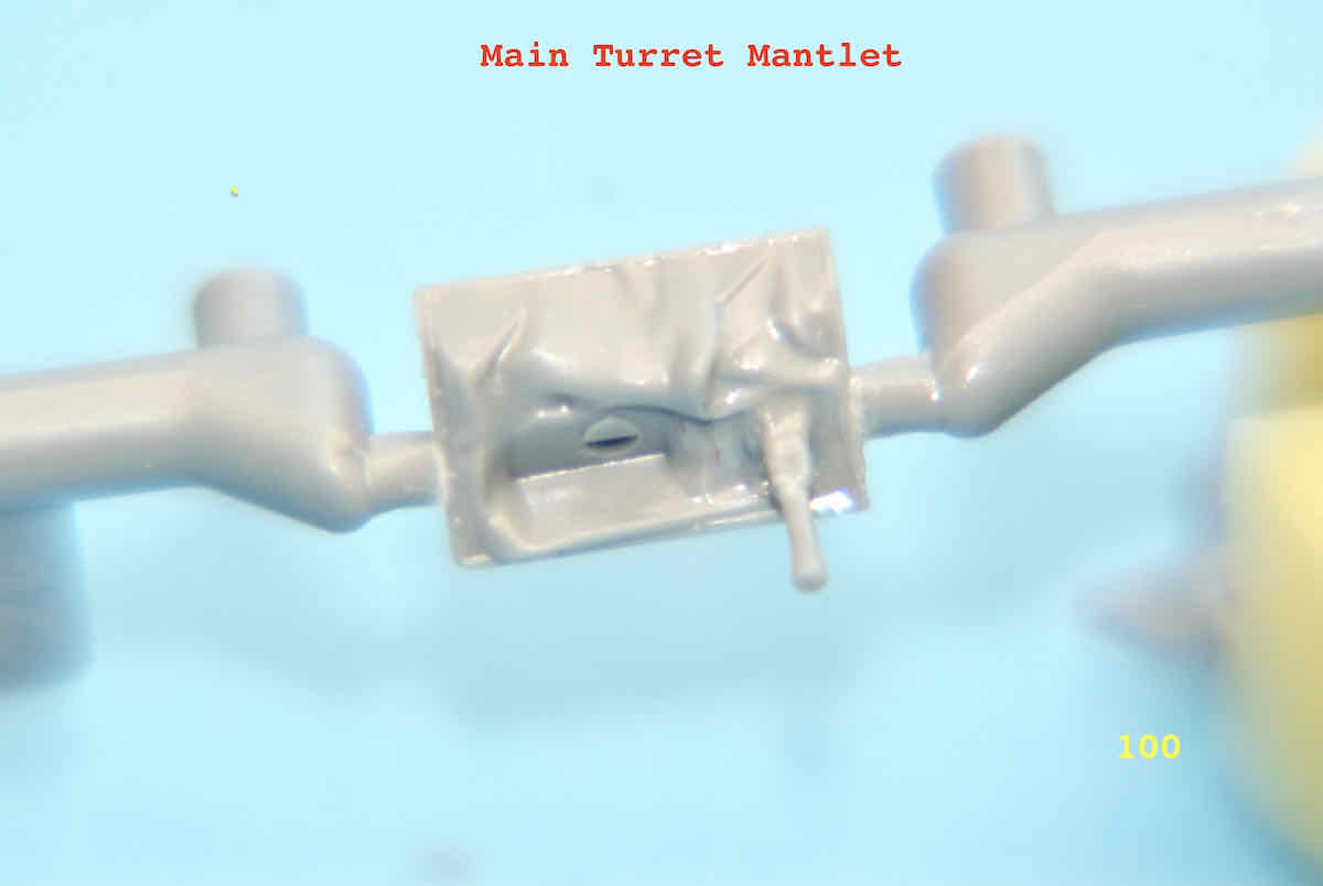
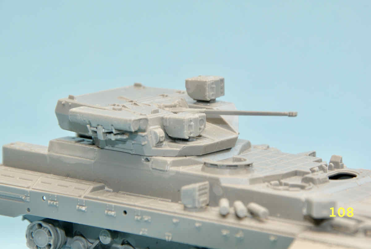
Greetings everyone watching this build. A bit of a diversion or change of scenery this update. I looked over the plans for the turret and decided to give it a try. The turret bottom, sides, back and top are all separate parts and will be aligned by nothing more than mitre joints and a few small locating tabs.I used Tamiya Limonene cement for initial placement of the parts and then when they were more or less dry I went over the joints with the Extra Thin version. Here are a few images of the first parts:
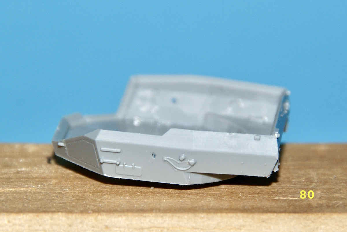
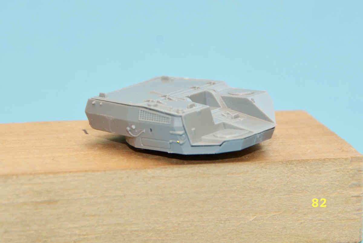
**NOTE:**while care needs to be taken when initially positioning the turret parts, if all pieces line up well the parts meshing is surprisingly good. Ideally minimal filling and sanding should be required.
Jan,
It’s coming along and looking good. The photo of the real thing with Putin taking a tour really puts the size of the monster in perspective. Perhaps you could post a pic of the build next to one of your other 1/72nd Russian vehicles as an added reference?
@ViperMX - Keith, thanks for dropping by having a look and the comment. Yes, the real thing is pretty big and that’s the reason I put up that Putin picture. As for images with other vehicles I’ll see what I can arrange once the build is a bit further along. A large number of my vehicles in this scale are mounted on somewhat limited sized bases to appear at model shows. Unfortunately the bases aren’t large enough to accommodate a vehicle of this size in addition to the one already mounted. But, I’ll see what I can come up with.
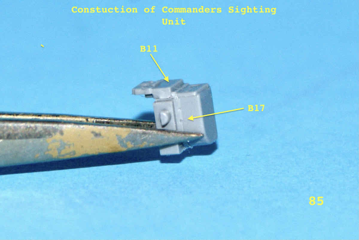
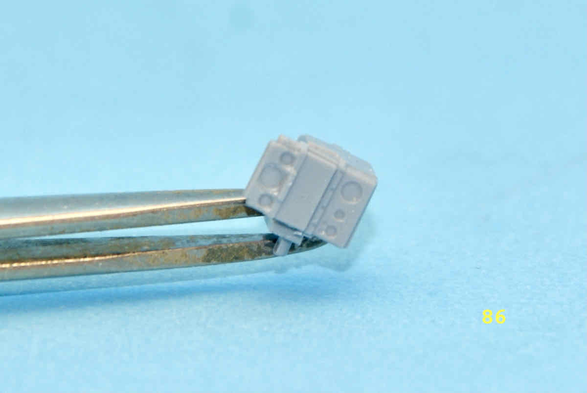
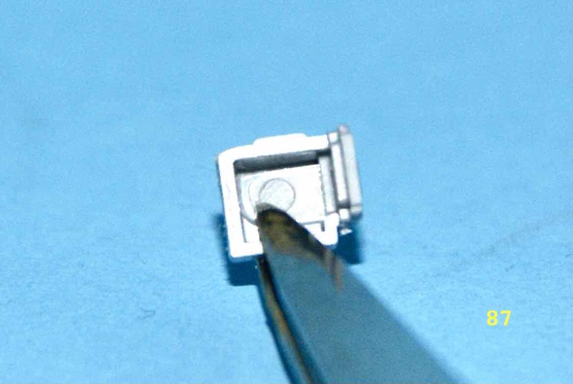
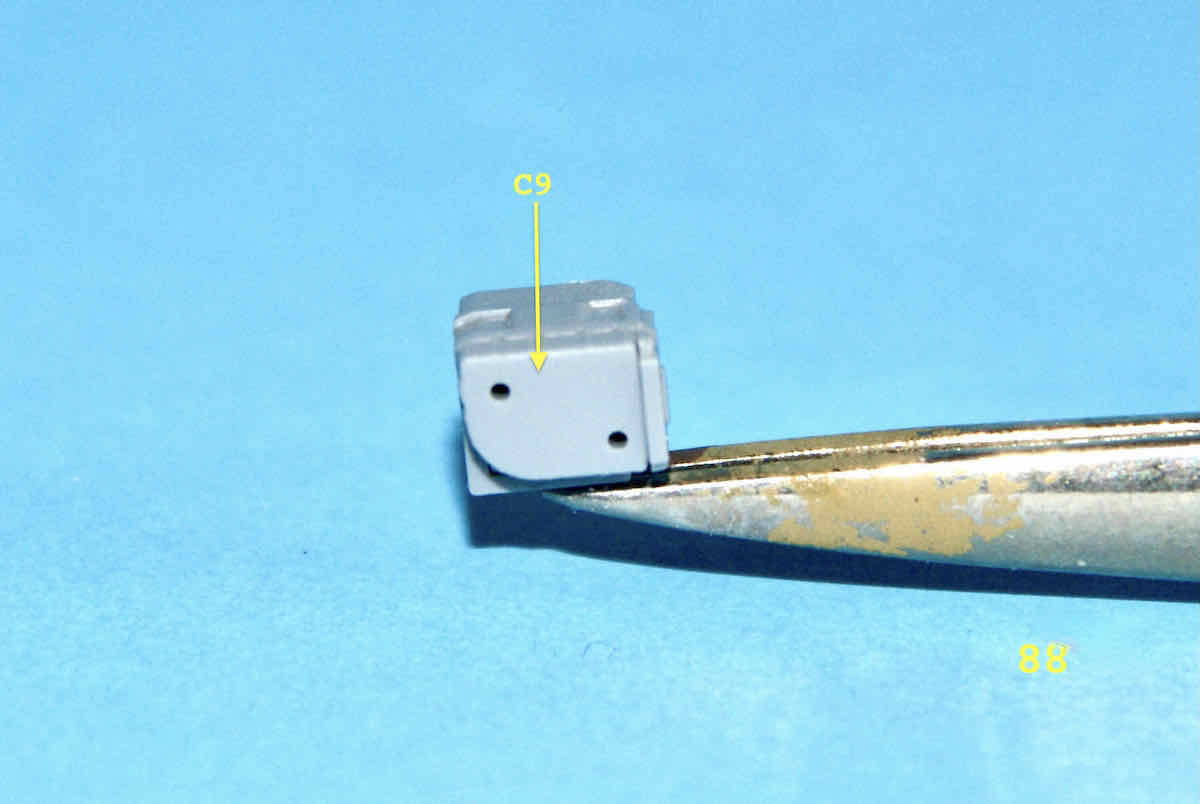
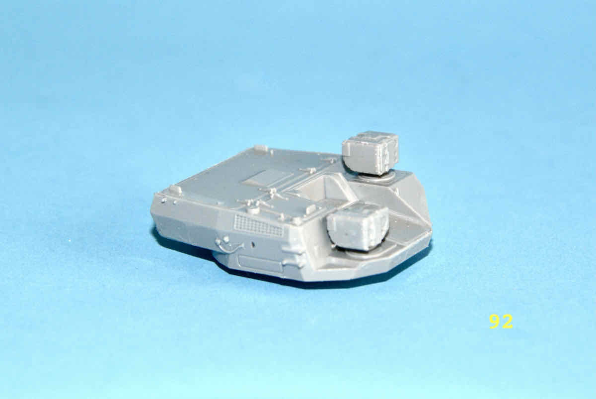
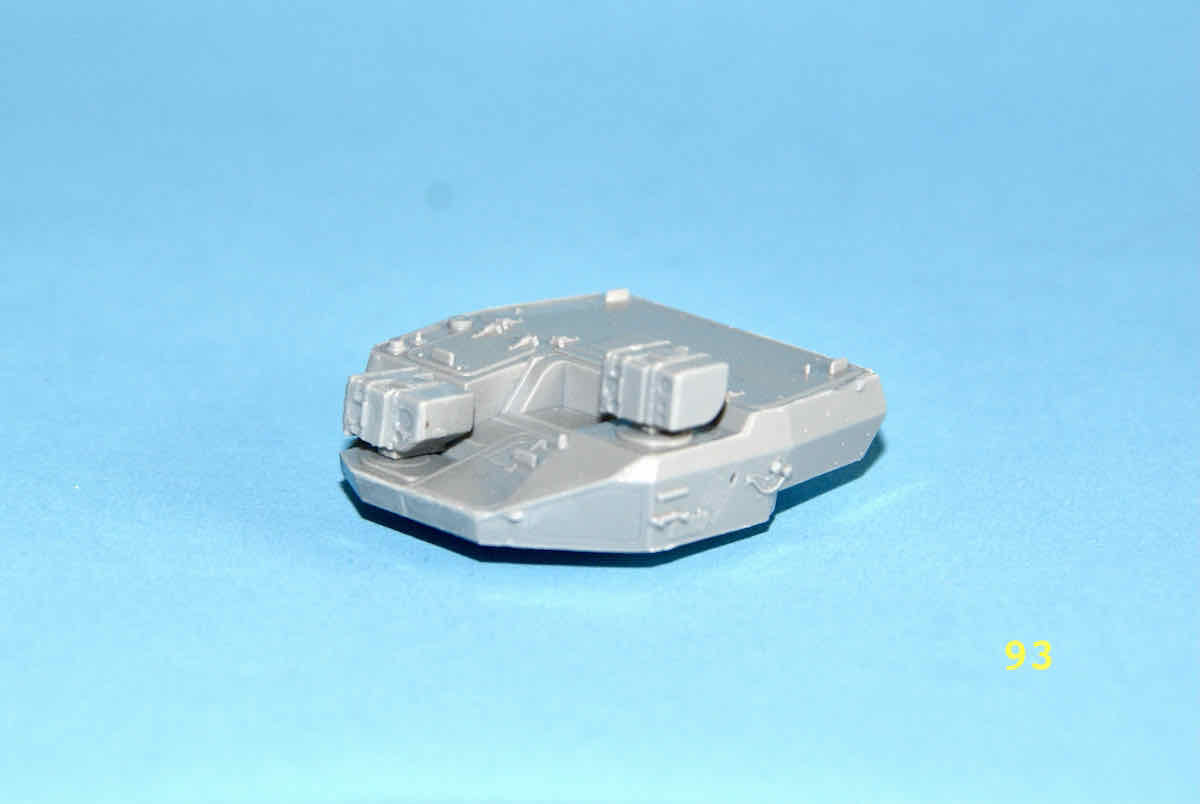
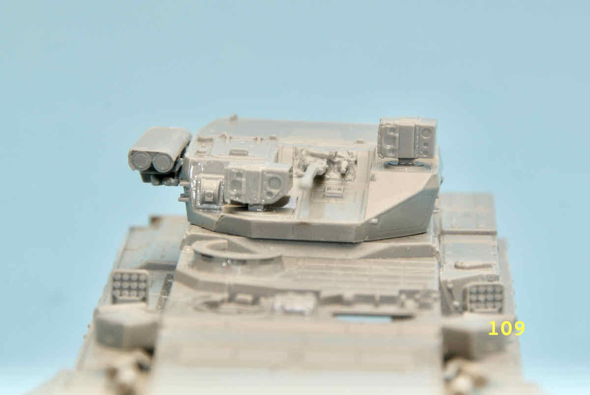
Over the last little while I tackled assembling two larger turret mounted sighting units. Both are made up of four different sized pieces, three for their bodies and one for their front or face. I assembled the gunners sight unit first but then took images while assembling the commanders sight. Both sights re roughly 5 millimetres square and 4 millimetres tall. Here are the images of the commanders sight assembly:
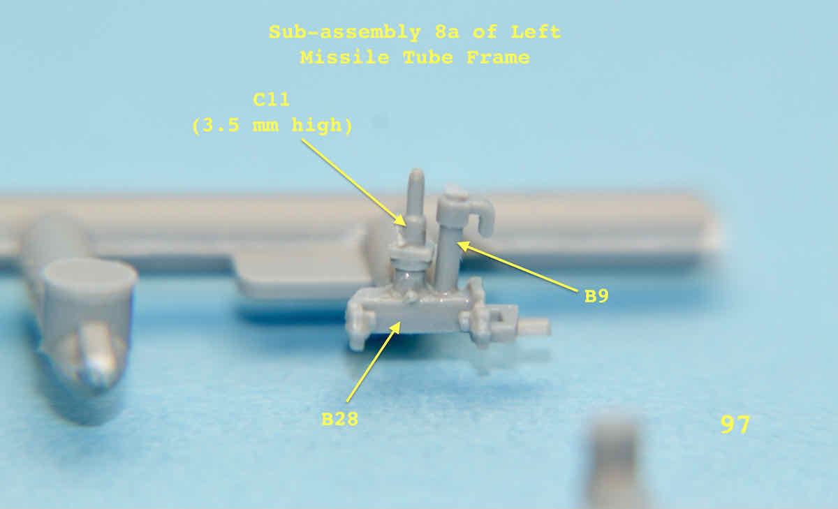
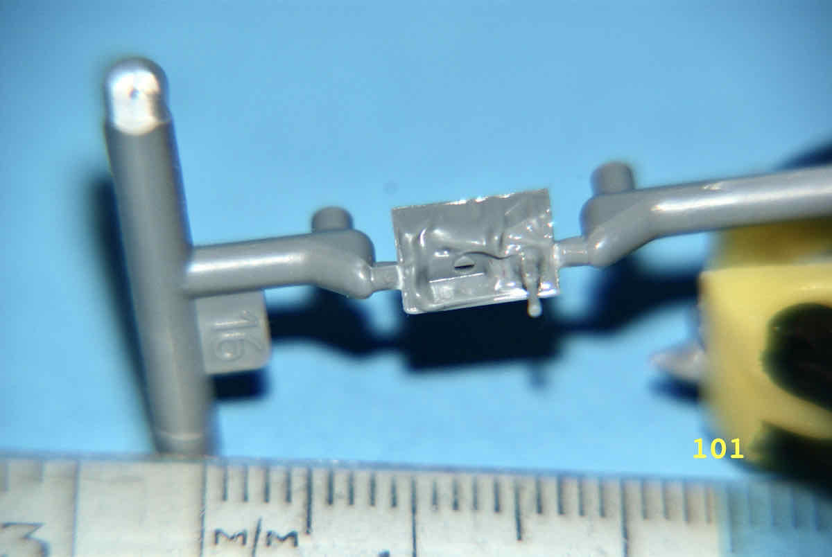
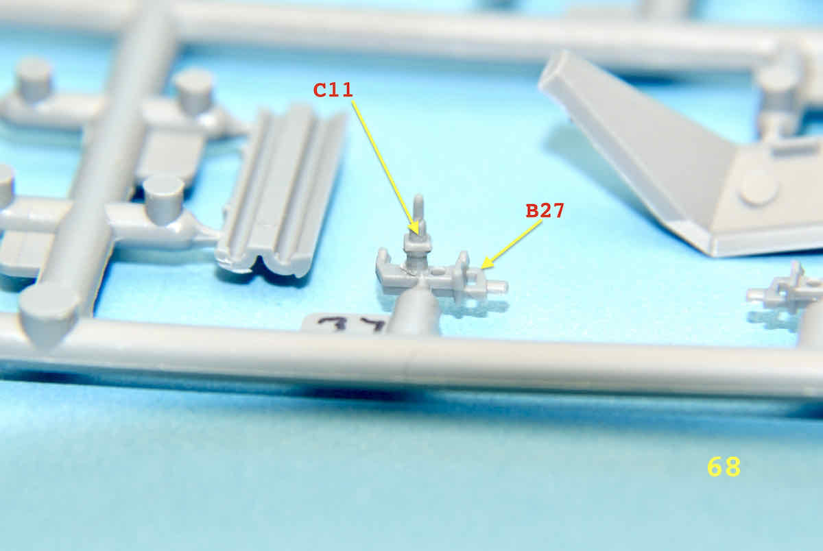
Been a while but the build has continued although a bit slower than I had hoped. I started on the first sub-assembly of the left ATGM tubes frame. This is basically the same type of assembly as was first seen back in pictures #68, #69 and #70.
I have noted the size of the Part C11 so that an idea of the size of these items can be appreciated.
All the images in this update were taken with a 250 mm lens with a 4X Macro filter attached for better viewing. The parts have half moon pegs that fit into corresponding half moon holes so you cant’t help but get them aligned properly.
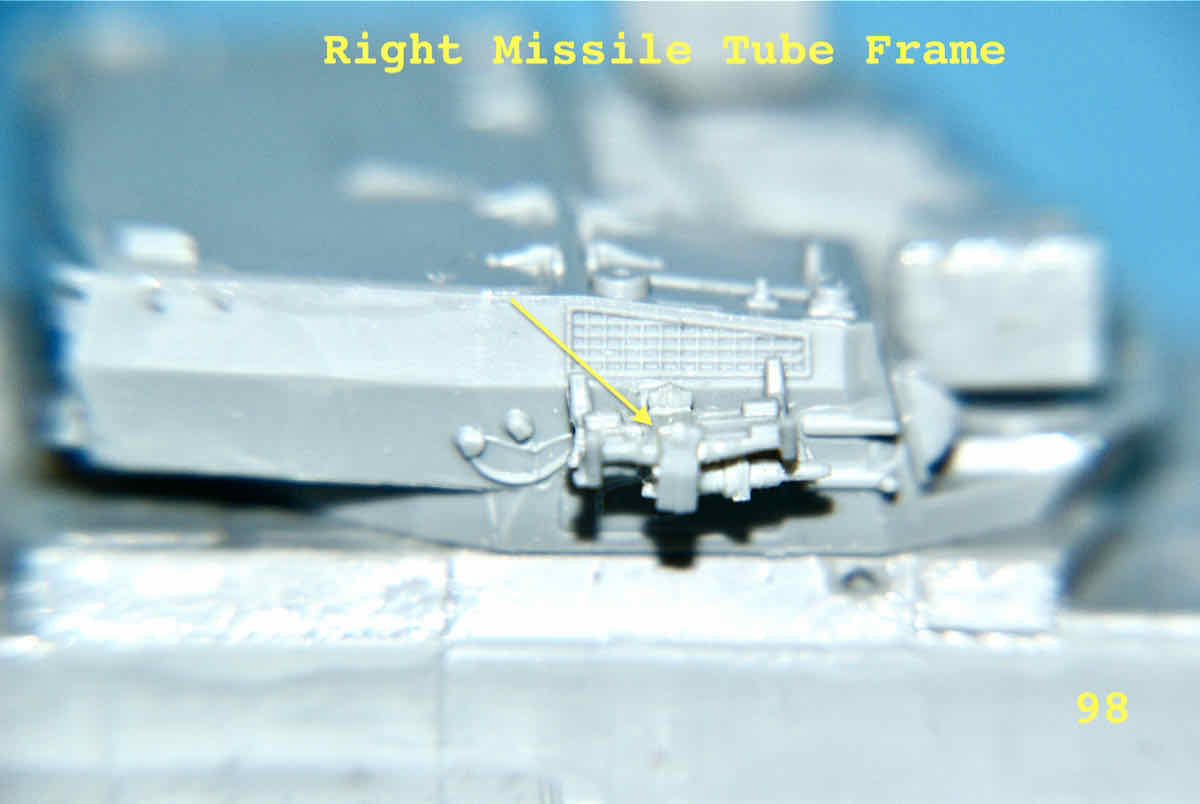
I have finished the right missile frame assembly and mounted it on the turret side. Here are a couple of images of the mounted frame.
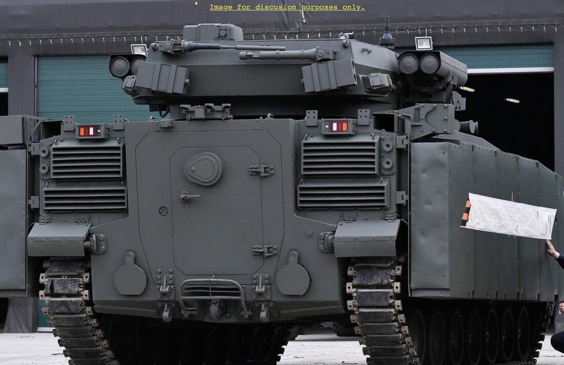
I know that it’s been a couple of weeks since my last update on this project but sometimes “real life” has a way of dislodging the best laid plans. While the instructions are generally adequate for most items I found that assembling the missile launch tubes did not have the clearest drawing of the parts. I must have scanned scores of pictures of the T-15 looking for images that would clarify a few points. One thing I did find is the proper orientation of the missile tube mounting frame. As a picture is worth “1000 word”.
The text in red pretty much sums up the most important point in assembling the missile components. Other than the above unannotated image there is no other way to keep everything aligned. Each sides missile unit is VERY side specific. Another thing to note is that the missile unit end parts are also location specific. While the parts are numbered the drawing fail to show any difference in the front and back parts. I found a couple of images to show the difference via a general Internet search.
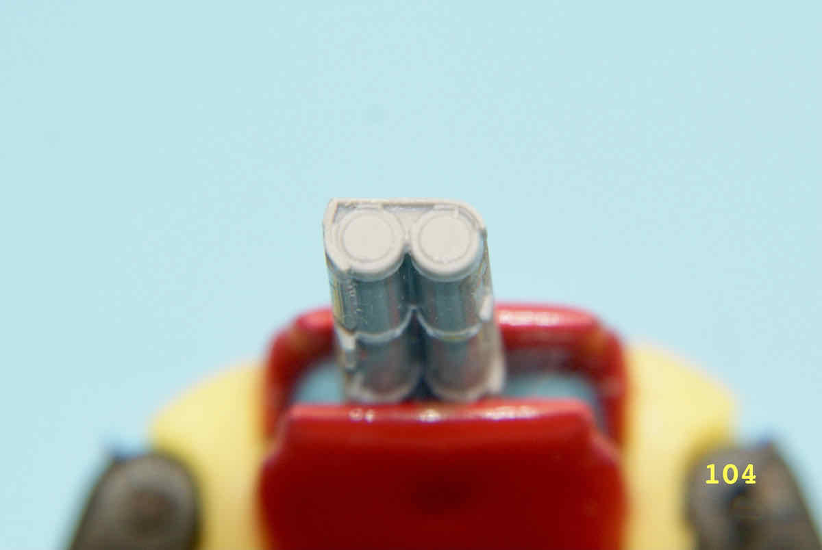
AS you can see in the images the front tube covers are for the most part flat while the rear covers have a specific contour to them. On the model parts they are represented as:
FRONT
It is also worth noting that shroud covering the missile tubes comes down lower on the side furthest away from the turret. The shorter end is nearest the turret.
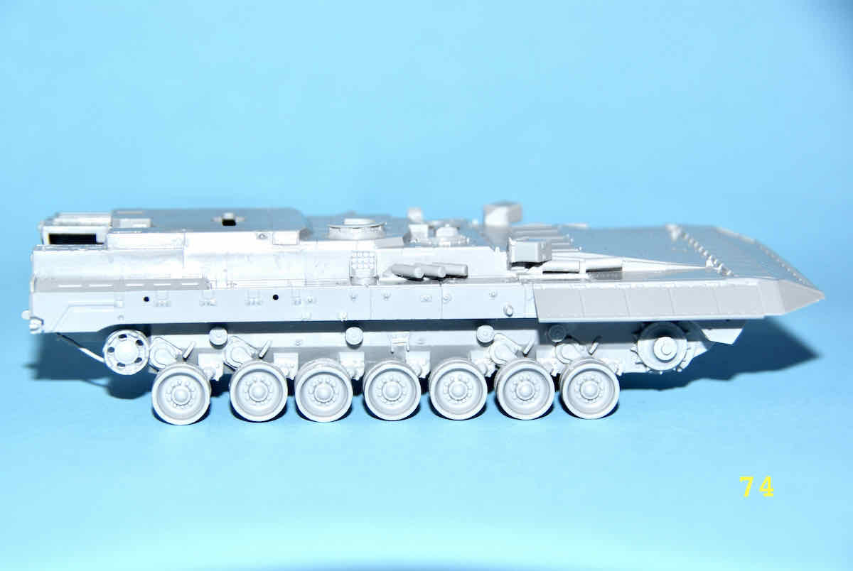
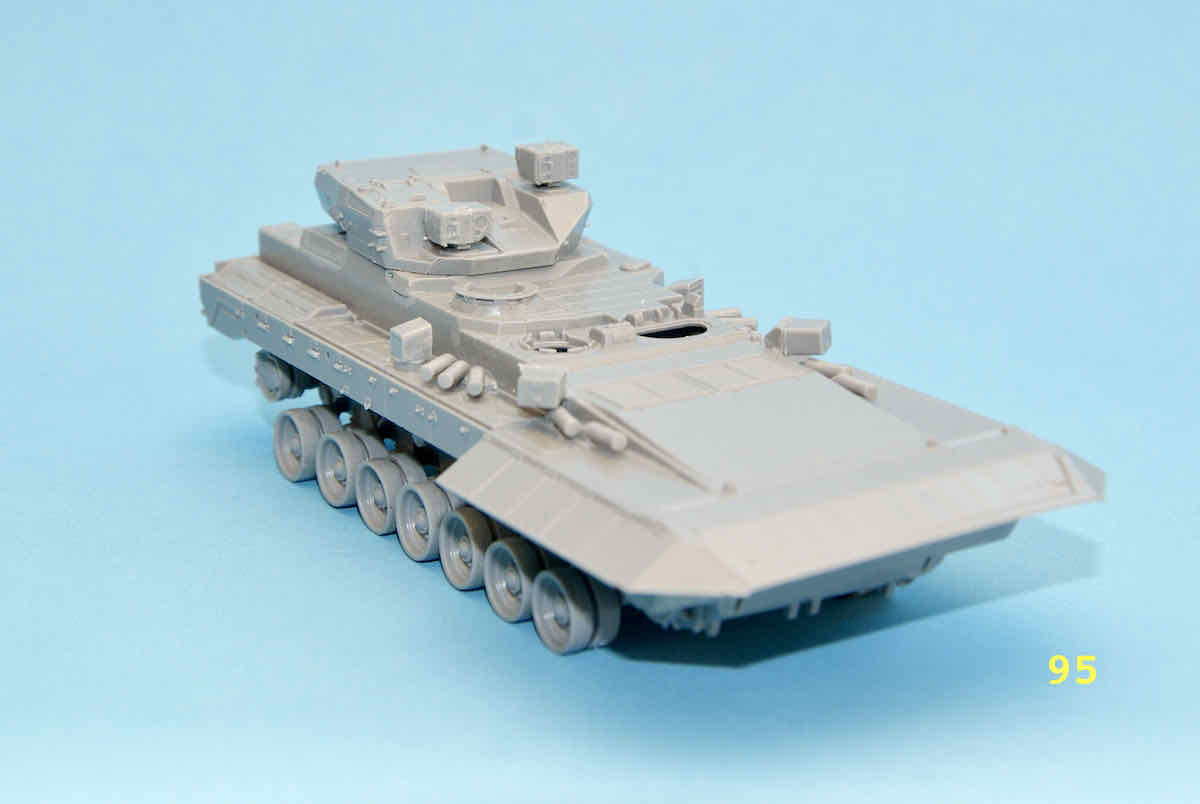
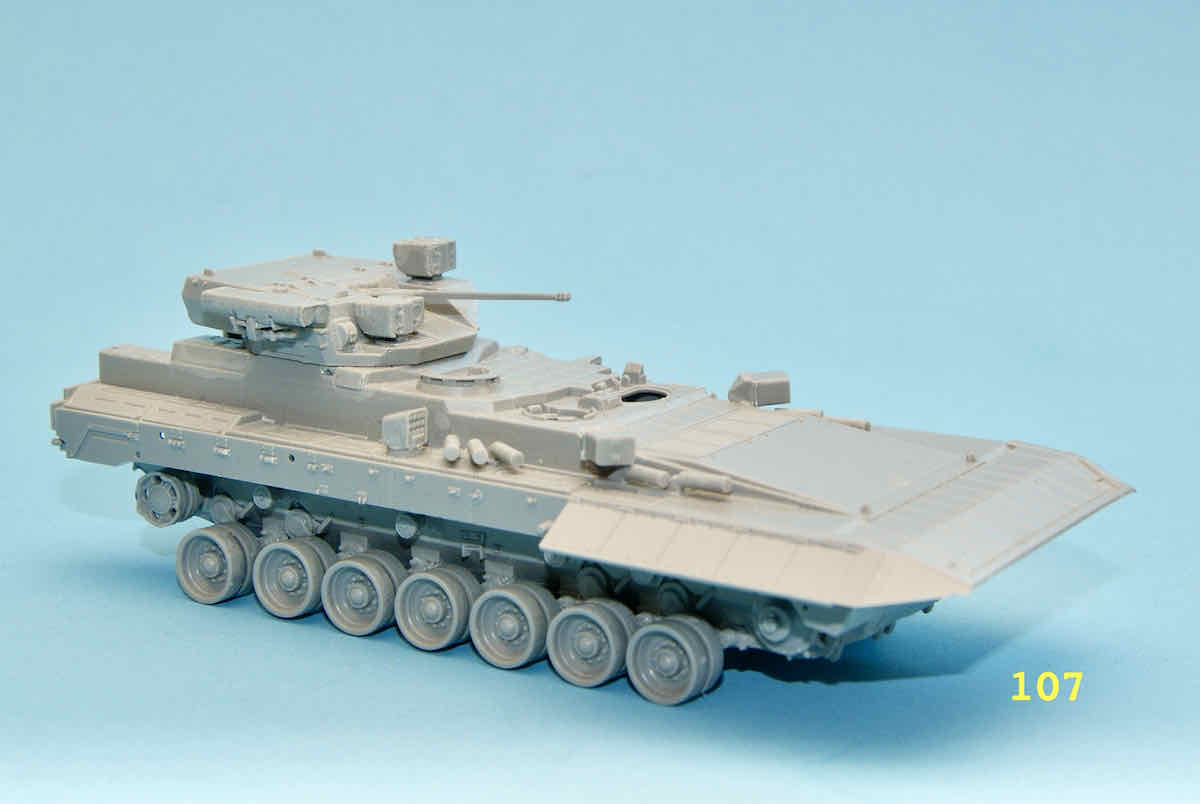
Finally a few images of the TBMP-15 dry assembled.
Merci Oliver pour vos commentaires. Si vous pensez que le “bec” est étrange, attendez qu’il soit plus construit! Painting this “beast” is going to be an interesting endeavour as it has some, to put it kindly, unusual angles and quasi-hidden spaces that are just visible enough to require painting. However, there is still the rest of the construction to deal with. BTW, a large segment of the “beak” are actually reactive armour panels.
Jan, I must say that your blog isn’t inspiring me to want to tackle this kit myself, it looks very fiddly and I have some form in losing minor pieces part way through builds.
I am interested though to see how you take on the tracks and what looks like reactive side armour slabs, and the painting sequence. I assume the top is still only dry fitted?
If I had (insert appropriate currency here) for every part that I have dropped and then been on my knees hunting down while holding a portable illumination device, I could start my own model manufacturing empire? But in all seriousness, it is indeed a royal fiddly kit but also rewarding to bring the kits’ misbehaving parts to submit to their final and appropriate resting place.
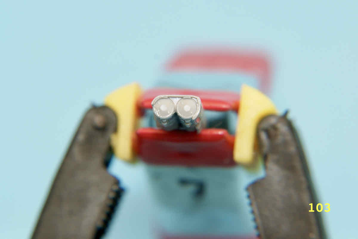
As I had mentioned above to Oliver, there are still a number of parts to manipulate and assemble before I tackle the “joys” of determining how and when to start the painting processes. You might also have noticed the beast still hasn’t had its headlights mounted as I have dreaded having to deal with their placement and that of the “brush-guards” associated with them.
You are also correct in assuming the the top hull is just dry fit as also so are the road wheels as I mull over how tackle the painting of the suspension area. I’ve done very little painting in the last few years so I’m a little leery of what my dormant skills might produce.
Anyway thank you for dropping by, having a look and the comment. The T-15 is no Airfix Tiger I but it does have a few of its own issues.
I’m certain that I would be using a dedicated set of vison visors at every step of the way just to be sure that I’m placing each of the parts in the correct area and arrange them correctly.
I’m just not getting in the amount of bench time that I would like so it’s nice to see that one of us is getting in a little more of that time, hope you are having fun and keep up the good work.
…sounding likely candidates to get knocked off just when you’ve almost completely finished painting it! I managed to do exactly that with a headlight on that Unic halftrack I did last year.
Thanks for the kudos Eddy. When appropriate, and in this models’ case there are a few, times when a pair of 5X Opti-visors sure come in handy. Along with them a set of Flex-i-File micro tip tweezers will also be a fine and helpful companion.
Bench time is also at times an elusive commodity especially under these pandemic times. However, I study the instructions at each free moment I have and plan out what I can efficiently accomplish in the time available.


 I’ve taken a slight break from the boredom or monotony of doing road wheels. Part of STEP 5 is construction the cradles on which the two pairs of ATGM tubes are mounted. The construction is listed as subassembly 7a and involves four rather small parts. Here’s the illustration:
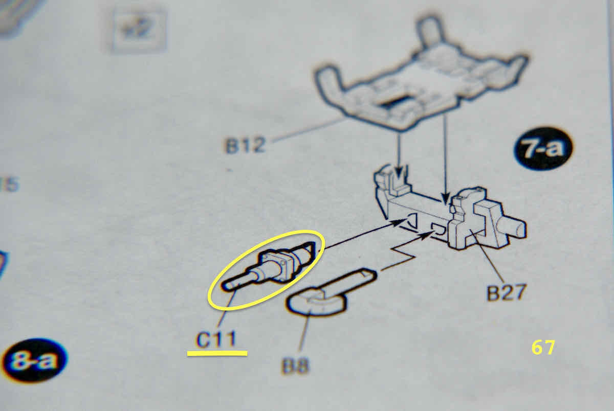


 It was a tough battle but I showed no mercy?
  I had used Limoneme cement as its slower drying time gives you more working time to align those microscopic pimples with their corresponding dimples.