A Brute! Converting Scammell Pioneer to Explorer off road recovery - all of it

Hello gents,

This is a project I’ve wondered about doing for a while, and of all things, watching off road recoveries on Youtube was the catalyst to go for it.

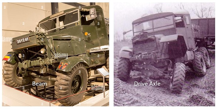
First up, you can see the difference between the two trucks below:

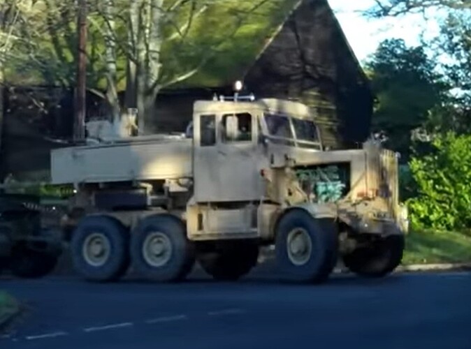
How about this bad boy!?! what a rig! On the left is a Pioneer, which is a 6x4, and on the right, an Explorer, which is a 6x6!! Awesome!! Making it more interesting, the front end on both is a three (really a 2 link) link set up, with a central axle pivot - wow…

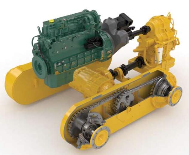
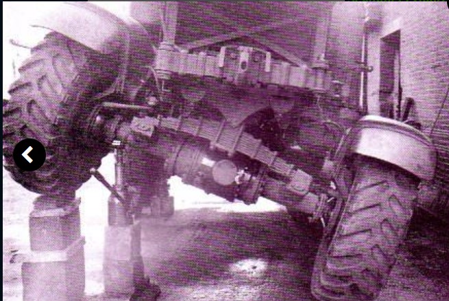
And on the really weird side, the rear - well, it took a guy a while to figure out what is going on back there. While the rear is a tandem, it is powered by a central differential and drive axles - but instead of connecting directly to wheels, the axles plug into what is essentially a long planetary gearbox/walking beam, which has two outputs, one for each rear wheel - and the whole thing pivots on the primary drive axle - wow again!
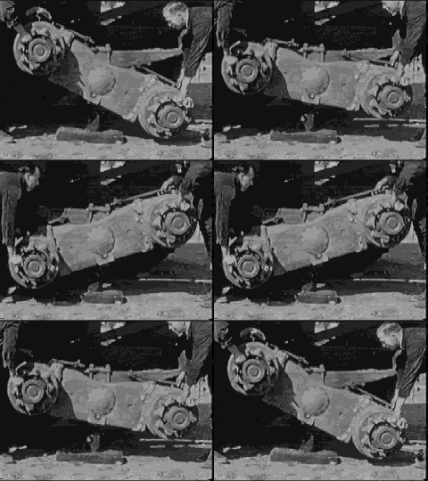
walkingbeam2

Evidently this concept is novel enough that someone made the GIF above - a bit silly, but you get the point! It’s very cool!

Not to be out done, the front end is pretty unique too:

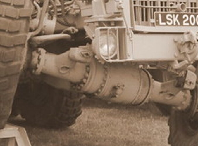
How about that?! yep - it looks a lot like a three link, but, it is in fact…a two link setup! Wow. There is the central pivot you see above, and behind it a a “V” or acutely shaped “U” tube attached to the inside of the axle, that projects toward the center of the truck, with another central pivot - again - wow…

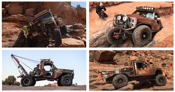
And why think about this now? well, watching off road recoveries in Utah:

My two case studies - As you can see, they are both, or were at some point, square body Chevies - but don’t be fooled - they are both highly modified and remarkably capable off road trucks.

This made a guy think - what if a Scammell Pioneer, were a 6x6? what might its off road capability be? At this point, I didn’t know there is a Scammell Explorer, which is indeed 6x6 - alas - no kit, so, instead a project!

Back to the two Chevies:

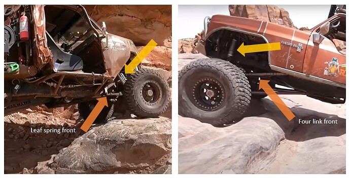
A key difference between the two is the truck on the left uses front leaf springs, and the truck on the right, four links (orange arrows). Something else to note (yellow arrows) the truck on the left has shocks mounted behind the axle, to allow spring rotation, while on the right, struts are mounted directly above the axle.

My conversion will be closer to the four link setup - but, I don’t know if it may become a three link? It is unlikely I’ll try the two link.

And here we are today:

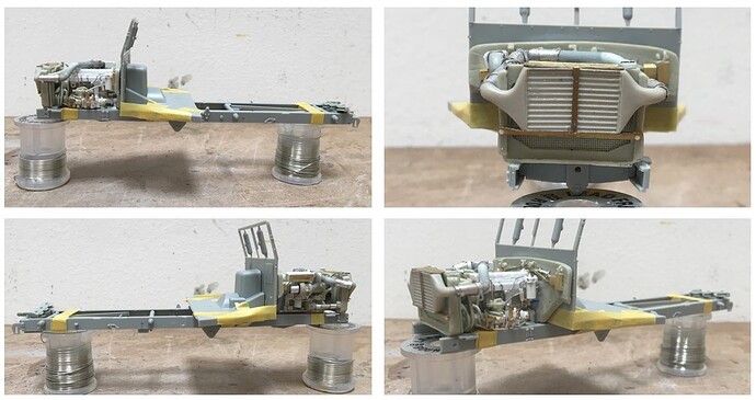
Over the weekend I got after making my version of the Cummins L10. This part - well, the donor kit doesn’t look much like the real deal, so I did some heavy modification, and well, the top of the engine, it’s wrong. I can live with that because it will have a hood over it. But - it will not have side panels and the engine will visible!

Like this, where a guy did this engine swap:

What a beauty! :smiley: This though, is an actual Explorer, with a Cummins L10, but no intercooler - which I want - which of course served as my motivation to make mine left hand drive - I couldn’t make room for the turbo and crossovers otherwise.

OK, enough intro - I’ll get after it -

Cheers

Nick
11 Likes

Didn’t understand a word of that explanation :thinking: but I will be following along to learn something new!

cheers
Michael

5 Likes

Tagging along ( for hopefully not a bumpy ride :rofl: :rofl:)

2 Likes

Hell yeah, outstanding! This will be a whole heap of fun.

Cheers, D

2 Likes

I’m with @cosimodo: didn’t understand a bit, but will hop in the back anyway…

2 Likes

Currently out of production …
:cry:

A pdf of a magazine from 1952 about the Explorer

Restoration blog, maybe some of the pictures may be of interest

The pivoting tandem axle with transmission inside is used on road graders,
sometimes(always??) those use a chain drive inside that pivoting beam.

2 Likes

Hi guys, thanks for dropping by, and your interest in the project.

@cosimodo, hi Michael, ha - yes…my effusive rambling text…you’re right! As clear as the mud this can drive right through :smile: In a shorter version: a truck with unique off-road capability and unusual suspension - fingers crossed I can do this :sweat:

@Johnnych01, bumpy ride? what could go wrong here? :smile:

@AussieReg, Hi D - you know I wanted to put a big block Chevy into this…alas, it’s heavy! and sticking with a giant diesel was the way to go…tho Cadillac did produce a 572 cubic inch big block in the early 70s… :thinking:

@golikell hi Erwin, yes, hop aboard! this may be a short ride! I have an overall build concept in mind, but man - it’s harder to do this in 1/35 than 1/25, and, as I don’t have any tools beyond the basics we all have - how to make small fittings etc- but, I will try

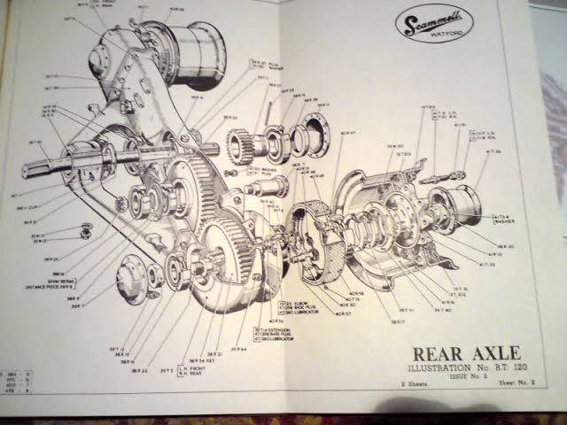
@Uncle-Heavy, Hi Robin, thanks for the PDF - good stuff and helpful. The rear bogey has had me wondering for some time now, as I have read a variety of articles, which clearly state: this is a chain drive, or this is a gear drive…perfect. That said, I have this image which sure looks like a gear drive:

Rear axle diagram_big

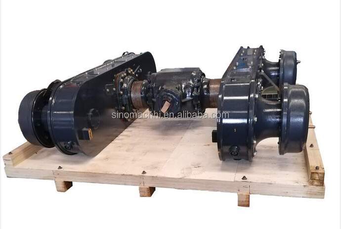
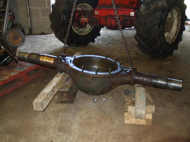
Whether gear or chain drive, I can’t imagine the spec on the drive axles - wow - it sure appears that there would be a lot of torque there. I wonder if those axles/splines lasted long? The (single) rear diff is huge:

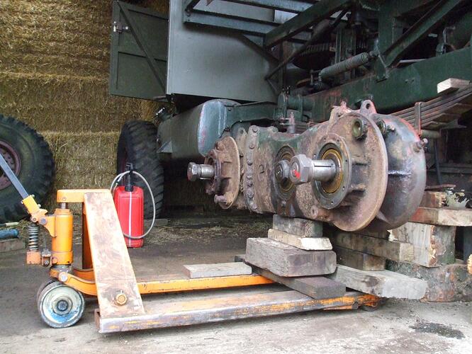
And the bogeys:

I think this photo is a bit deceptive as the axle pinions make this look fairly “normal” in size - until you compare the bogey to the size of the pallet jack - this is a big unit.

Thanks for having a look -
Cheers
Nick

5 Likes

Ain’t no doubt about it, that image is a gear drive.

image

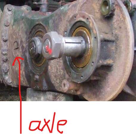
That axle end is not present on the chain drives on graders, compare with
the two images I posted.

Durability: some of the Pioneers and Explorers were busy up into the eighties
so I guess they were built to last.

Maybe they do chains because it is easier to maintain? Less greasy points?
The M26 tractor from roughly the same decade used visible chains …

2 Likes

Well guys,

Rather than starting with the rear suspension, as discussed above, a guy started up front. Happily, I have been able to find several images of Scammell Explorers and Constructors, both of which are 6x6 versions of the Pioneer.

As was hopefully clear enough in my rambling above, the front axle and suspension is not conventional:

6x6 axle

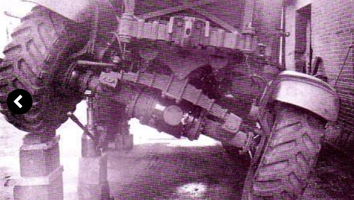
So, as you see in this picture, there is centrally located spring, from which the axle pivots. In the lower picture you can see a detail of how the spring is attached to the axle. Those brackets must be remarkably strong. Among the various oddities is that there doesn’t appear to be shock absorbers or springs of any type to control the motion of the axle.

What you can’t see here, is that there is a single, generally “V” shaped link behind the axle, which I image works something like a sway or panhard bar - tho, the more I think about it, the less I understand the engineering behind this :thinking: The basic geometry is very simple - the front axle essentially operates like a teeter-totter:

With drive wheels where the riders sit :smile:

But, being an off-road driving truck enthusiast, I am amazed by the stress placed on the brackets that mount the leaf springs to the axle, and the pivot bracket which is used to mount the leaf spring to the chassis :thinking:

After more pondering, went about making one of these:

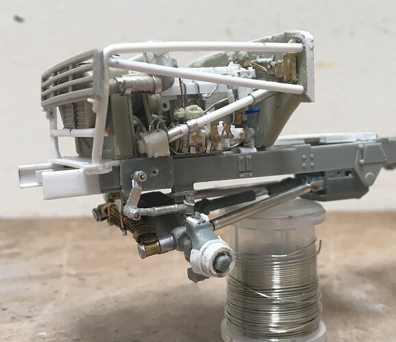
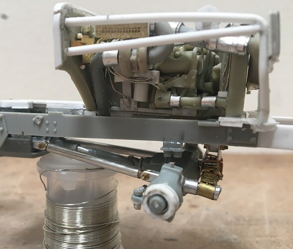
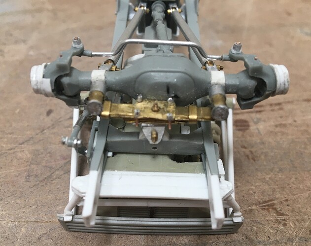
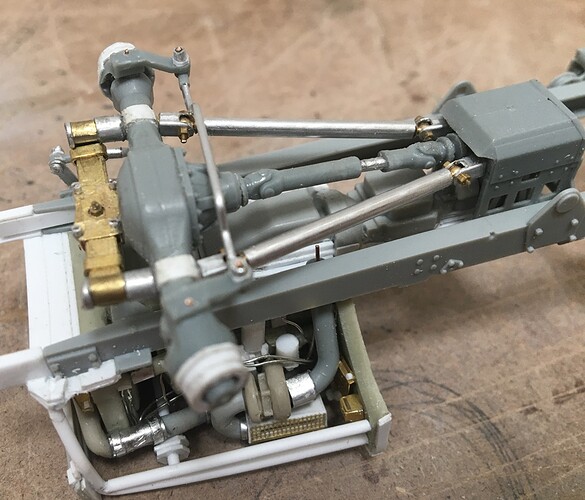
So here you have it - this was not easy to make. There is a lot going on up here. The pivot and forward facing elements of the axle and suspension are a fairly reasonable representation of the real deal.

The rear, not so much. Rather than wrestling with the “V” shaped link, I made two link arms, tied to the transfer case mount (not the transfer case itself) because it is tied back to the chassis. If this were a contemporary multi-link setup, a bracket located in the same place would be attached to the chassis, with the transfer case above. But, as I had this remnant transfer case, it went in, and worked fine.

While going after this level of detail, I clearly needed to make the steering posable :smile: Easier said than done. The axles and knuckles are from an old Kinetic kit, and they did not go together well, and seemed to take an awfully long time to make, both in terms of getting the Kinetic parts to work, and to get spindles set up to match the tires/wheels I’m using.

As there are so many moving parts being used, well, they each needed to be made and then adjusted several times to work. Adding to this, I’m using different bigger tires than the original - which meant checking for vertical clearance in both the typical “tilting” motion of the axle, but in the “turned” and tilted motion as well. I eventually added bump stops to the chassis to limit axle travel. Then made up a steering gearbox and column.

While this area is still reasonably accessible, I’ll add the exhaust pipe - if you look carefully, you can see the metal pin I placed in the pipe behind the turbocharger.

OK, that seems like enough text, thanks for looking, and have a great weekend -

Cheers
Nick

14 Likes

Yes, of course you are. Who else would tackle this project. Looking forward to this as progress is already looking full of detail.

4 Likes

Nick - Watching and enjoying this for sure ! Nice work going on here.
Cheers- Richard

3 Likes

The idea of all the detail that this will encompass is incredible… Really looking forward to watching this get engineered and scratch built

2 Likes

Unbelievable. Nick, your conceptualization, translation, and execution skills are astounding. Your scratchbuilding skills are just amazing. I don’t know whether it’s the wonky design or your extreme talent, but I can’t believe the detail and intricacy of the model that is taking shape here.

4 Likes

Breath taking detailed work, amazing project!

4 Likes

@Stickframe Nick, I’m sure I’ve said it before, but I’m happy to say it again here. You are a true madman! Of course, in a super-cool jaw-dropping genius sort of way, but mate, this is insane!

Cheers, D

4 Likes

Right, like brain surgery’s mildly less than straightforward sometimes…I like your line in English understatement :+1:

3 Likes

Hi model builders,

thanks for dropping by to have a look -

@KoSprueone, thanks KSO. I’d been pondering this idea for a while - just seemed like the right time to pull the trigger.

@RDT1953, hi Richard, thanks - I can say, I’m enjoying it too! That said, this has required a lot of do and redo… :smile:

@Johnnych01, hi John, seeing if I could make an operable/posable suspension in 1/35 had me wondering for a while. I’d thought about trying it on a Toyota or other small pickup, but at scale, I realized that yes, I could probably do it, but measured that against the hassle - the bigger truck won! Still a hassle, but not as bad as it could be!

@SSGToms, thanks Matt, I appreciate all of that. You hit the nail on head about the idea of trying this, the Scammell’s wonky suspension - really caught my eye and invited the why not try it question. The same for the engine swap, as while I was looking into this truck, I found a guy who did the same. I’m not sure I made the right choice with converting the engine I did - I think I would have been smarter to use an RFM engine from and MATV, but, I still want to use it in the actual kit!

@Armor_Buff, thanks and glad you like it so far. I’ve built a few suspensions already, so have worked out some of the steps and methods required to make it posable, which essentially forces some of the detail, especially because it will be so obvious when finished . But, even if not that obvious, I enjoy the challenge :smiley:

@AussieReg, thanks D, and I’ll take that label! :smile:

@Dioramartin, well Tim, as I recall you are the fellow that has tackled and used an incredible amount of innovation to build a certain, remarkable dio…how hard can it be??? :smile: well, all of it!

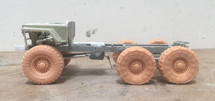
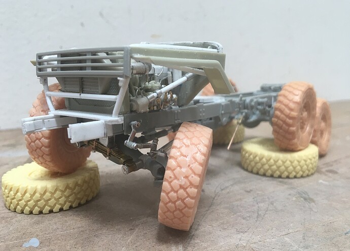
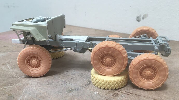
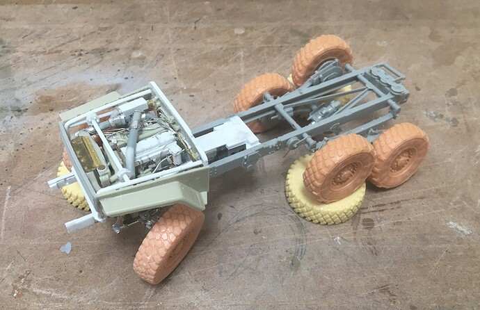
Work will keep me tied up next week, but I wanted to see if all of this worked - so pushed hard to get the rearend in place:

I usually struggle with getting all the wheels to sit flush - but for this the question was could I get the ride height correct, with a level chassis. Happily, as you can see above this worked! :smiley: :smiley: I might have been smarter to build the rearend first, and measure the height of the axle centerlines, and then transfer that dimension to the front axle spindle - but, well, I didn’t and instead hoped for the best.

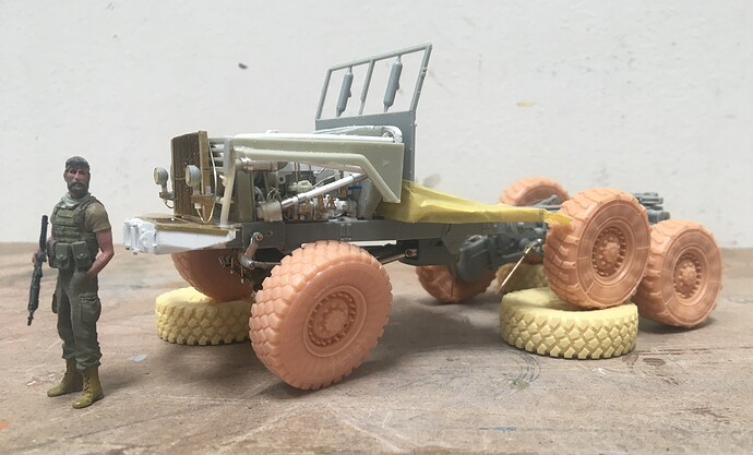
That said, my thinking was that if I tried to use specific dimensions, I’d likely cause myself lots of grief trying to achieve unachievable tolerances and would fail. And better news, it seems to work too:

I think these show the goal, which was to get this set up so that the front and rear would articulate in a convincing way. And for some scale:

The proportions of this have been a challenge for me - as at first glance, this might look like a 1/25 scale Jeep, rather than a 1/35 semi tractor - it’s short but really big!

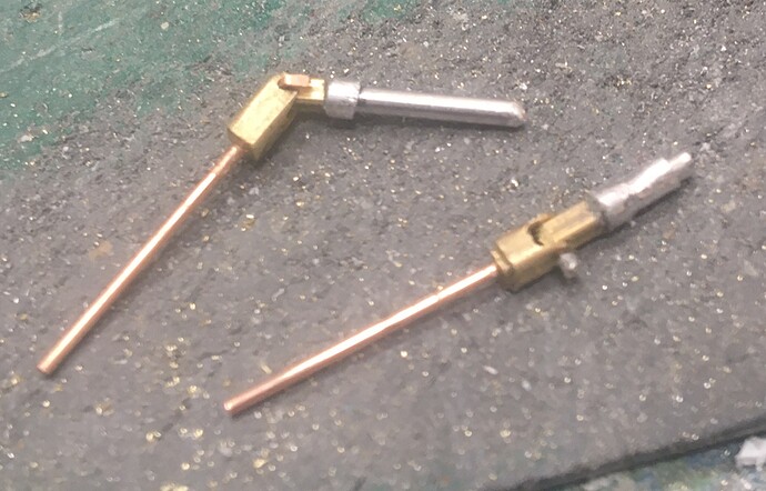
As for the dangling drivelines, I made up some small u-joints for the rear:

I should have done this for the front too, but they are a real pain to make - the smaller brass square tube is 1/16" - which means these parts are pretty small, and require patience while making.

The alu tubes will plug into the transfer case and rear differential, and a pair of concentric alu tubes will be used for the drive shaft and yoke, which will allow the two to move independently. I’ve tried a variety of ways to make U-joints, but have found this to be the most useful. They obviously don’t look quite right, but they do the trick!

So the plan is to get the driveline installed and then…back to real work for a while

Thanks for looking and happy model building -

Cheers,
Nick

7 Likes

Nick that’s very kind of you to say but most of it was/is quiet desperation (and yes, I am English if you get the Floyd ref), I think many of us are either engineers or closet-engineers (let’s not go there) so to see your ruthless mechanical logic creating nigh-on perfect scale replication is…well, insert synonym for extreme pleasure here.

In other words, WTF & OMG?! :exploding_head:

2 Likes

Once again: awesome work there. It obviously is a great feat to get everything working (as in moving ofcourse), but I wonder how you prevent it all clogging up with paint, when the time is there??

1 Like

My first and lasting imression …
There aren’t enough adjectives or synonyms in a Thesaurus to describe your work and talents , … that miniaturist lady missed the boat , … she should have done ya …

And Erwin , yet once again you’ve asked a question that proves you’re the Baby Ruth at the bottom of Bushwood Country Clubs swimming pool … still love ya tho …

2 Likes