I ask this, because it happens to me. I want to gain knowledge. This has nothing at all to do with critisism…
3 Likes
Answer from the spectator bench:
Airbrush.
An airbrush deposits paint on the surfaces that are “hit” by the air-paint spray.
Surfaces in the “shadow” or “around the corner” will not get any paint.
A hairbrush on the other hand will deposit wet paint which can get around
corners by capillary action and clog up everything.
Edit: Post upgrade with schematic image showing painting of the vent-grate on top of an M113
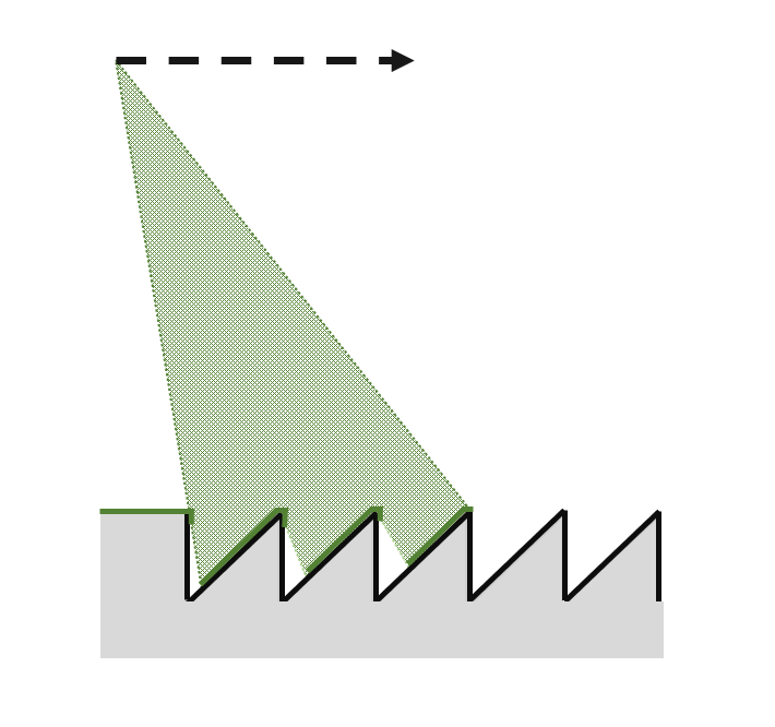
Gray plastic used for clarity (AFV-club). Plastic painted black and then a “green” or whatever coat
is added at an angle. Spraying vertically would smear the vertical edges of the grate so maybe
an 85 degree angle is useful. This will leave a small area of black in the bottom angle.
The zealous modeler could scrape out and undercut the vertical edges of the plastic for increased
realism …
3 Likes
Erwin , my point wasn’t about you critiquing his work , it was about us discussing painting such an involved , intricate build of Nick’s at our last BBQ meeting . Which was answered then .
Remember we asked Nick about it being a shame to paint all the work he did on his last build and questioned how involved it would be to paint it … which he answered .
2 Likes
I certainly do remember his answer, but in my memory we didn’t talk about keeping moving parts the way they are supposed to be: able to move… Whether Nick wants to pain such quality work, was also answered then. The answer was yes at the time…
@Uncle-Heavy Thanks for your explanation. Airbrushing is still not my best feat… Maybe, one day!
2 Likes
I switched to airbrushing because I could not get the results I wanted with the “hair”-brush.
Airbrushing made things easier for me since it was easier for me to learn how to handle an airbrush
than learning how to get good results with a “hair”-brush.
I use the “hair”-brush for:
- small details
- spin-painting wheels
- small areas where the paint will barely be seen
I still need to figure out how to paint narrow lines (French pre-war camo for instance).
2 Likes
The black lines on the St. Chamont I did by using a CD marker. I found out that some markers attack acryllic paint, but a CD marker doesn’t. Or do you mean other thin lines?
1 Like
I meant those lines. I haven’t tried the marker method yet but your results look very promising.
I prefer enamels so there shouldn’t be any issues with the paint getting attacked.
There are also some WW II German camo with thin (green?) lines snaking all over the place.
2 Likes
Never tried to tackle those… But there are green markers too, just don’t know if those are in the water resistant type too, as that is what you need…
2 Likes
Every part of that is exceptional … wow wow wow
4 Likes
Thanks to this topic I realised that I had almost missed out (You Snooze, You Lose)
on the Scammell Explorer kit (K127) by Accurate Armour (OOP, I found one in a shop in
Italy, Praise the Internet, Halleluja!)
This is how David Jane designed the front axle.
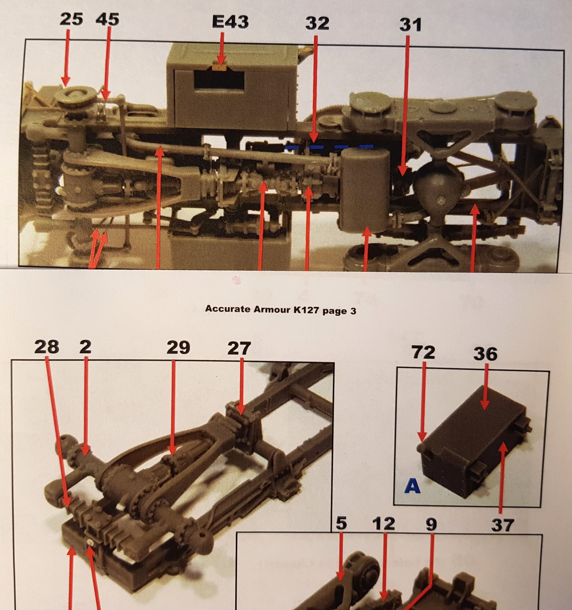
Click the image for a larger photo
3 Likes
I might look for another Striker then … theres always hope it might work out cheaper ![]()
1 Like
Hi guys,
Real work has kept me tied up, so, this stalled a bit.
@golikell, hi Erwin, yes, this will eventually get painted with an airbrush - after a rattle can primer. I tend to spray both from far away with a few layers. In addition to reducing the chances of getting big blobs of paint, I haven’t had much trouble with parts getting stuck together. I will then follow on with a brush on detailing.
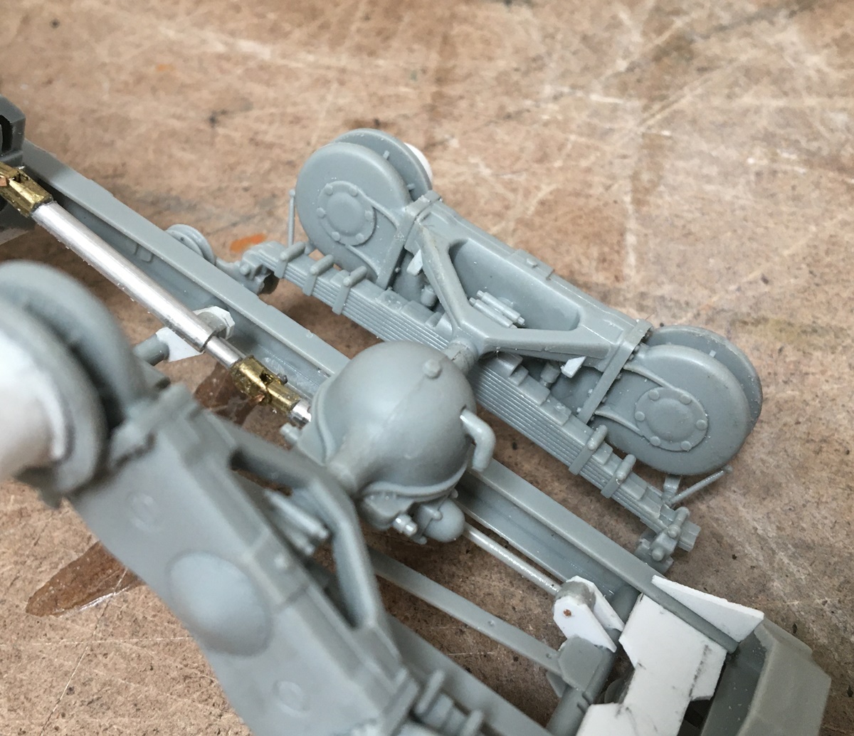
I’ve made some progress on the cab, but first, @Uncle-Heavy, Robin - wow! nice find! I’ve kept the basic suspension principles in tact, but changed the links in the front - a few chassis pics:
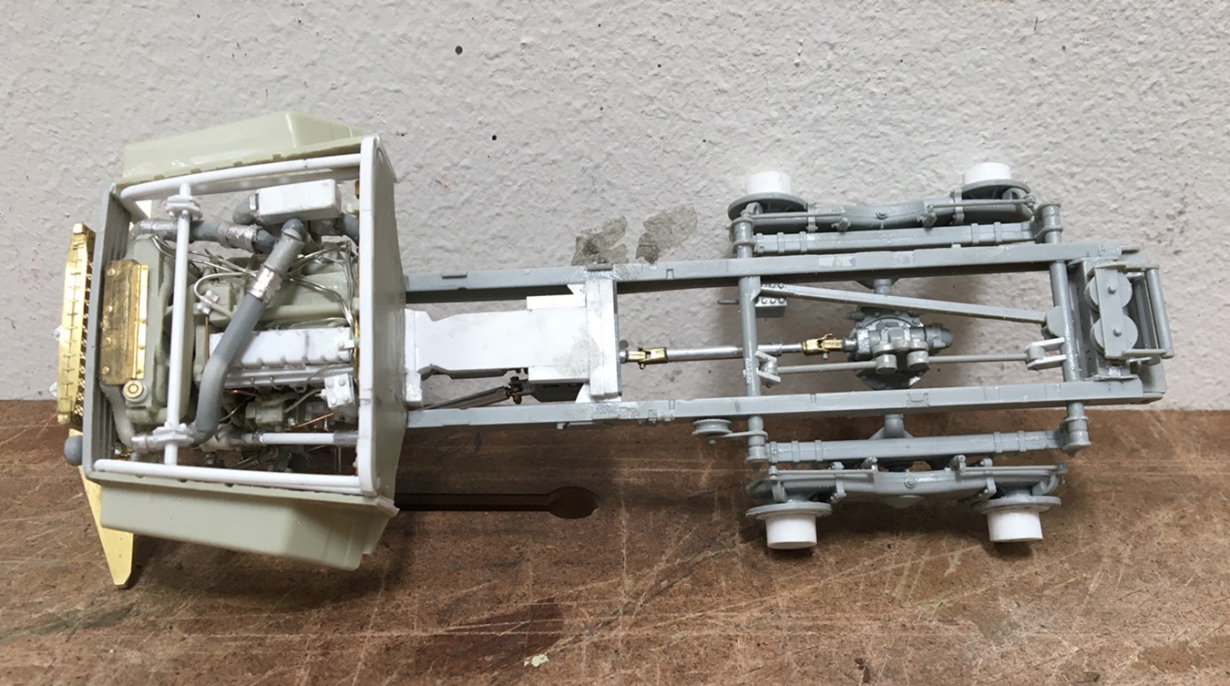

I added some torque arms to the rear - the basic engineering of this still has me a bit confused - as without any bump stops in the rear, I can’t tell how the driveshaft yokes wouldn’t pull apart under flex? So, in went the torque arms - is it right? no idea…
As I went about building the cab, I realized it was small, so made it a club cab - adding some length:
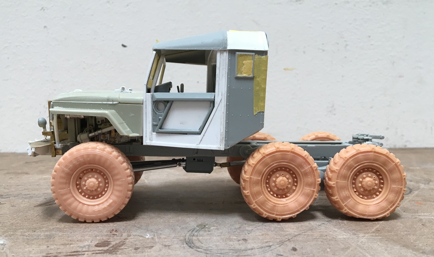
The cut in the back is to allow for the rear axle articulation:
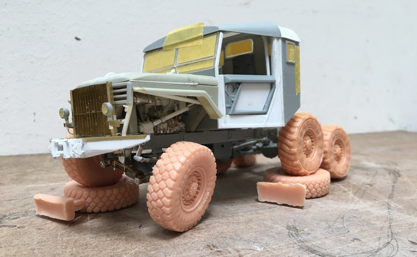
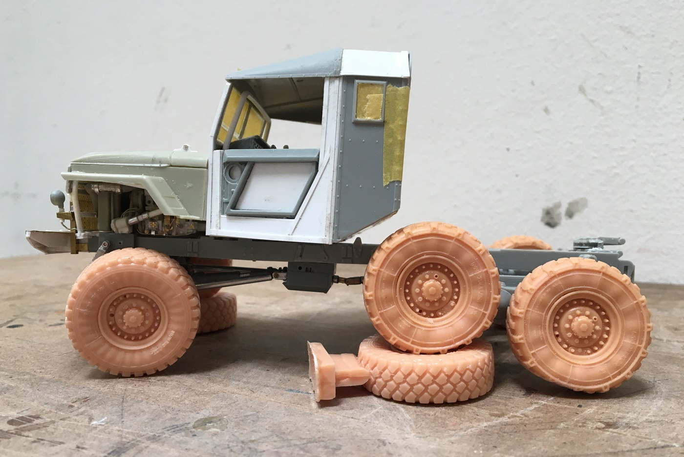
Still works and the cab is a bit more functional.

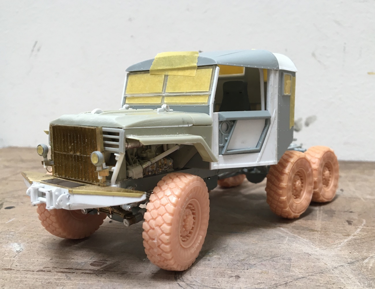
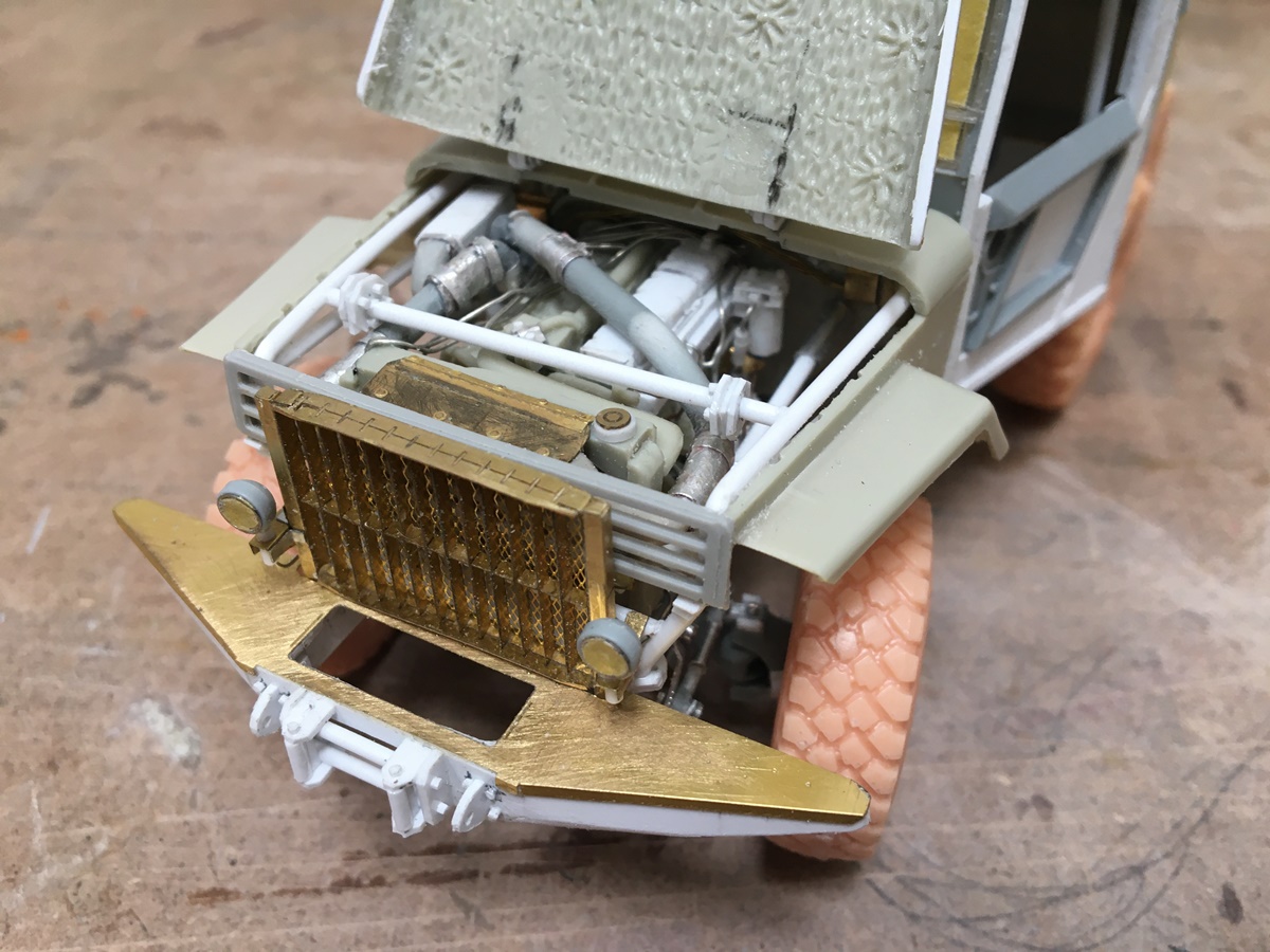
Still adding details here and there - the hood still opens despite my efforts to destroy the cab:

I tried to make the cab doors operable and gave up. I concluded it wasn’t worth the effort.
Because of the rear wheel movement the bed height will/could be high - so, I am pondering a hybrid to pull it together in a credible way. I was thinking about adding tool boxes over the wheels, but they might be too high to reach into!
Thinking of @Johnnych01, Johnny’s apocalyptic rig…this seems to be heading in that direction with so many changes - lol - not the original plan, but seems to look like it lol.
Anyway, on we go -
Cheers
Nick
11 Likes
Thats looking fantastic Nick. Those extra details are just incredible mate … real craftsmanship.
1 Like
You and me both, I think.
Drive shaft comes from the transferbox and goes to the differential in the center of the rear axle.
The rear axle is held in place by the springs. The driveshaft enters the diff on the top side.
The rear axle and diff sends power to the center (cog)wheel on each side. Up until this point the
whole thing could just as well be a 4x4 layout.
The single wheel on each side has relatives inside those big housings that can swing around
the rear axle. When the whole thing is compressed under load the rear end of the driveshaft will move a few inches upwards. If the axle swings sideways (wheels on one side in a hole and the other side rides over a bump) the top of the diff-housing will swing slightly left/right.
Where would the driveshaft yokes be pulled apart?
If the connection between the rear axle housing was very weak and a lot of torque was applied then maybe the whole differential and axle housing could try to rotate.
I could imagine problems if it was coil springs but if the axle is firmly connected to the leaf springs?
I have zero experience with design and functioning of off-road chassis so I’m just thinking aloud here.
The GMC 2½-ton 6x6 which had two rear axles in a bogie which could swing up/down has a lot more movement in the yokes when the two diff housings move in opposite directions.
The Explorer has this layout (OK, I simplify things but it is the general principle)
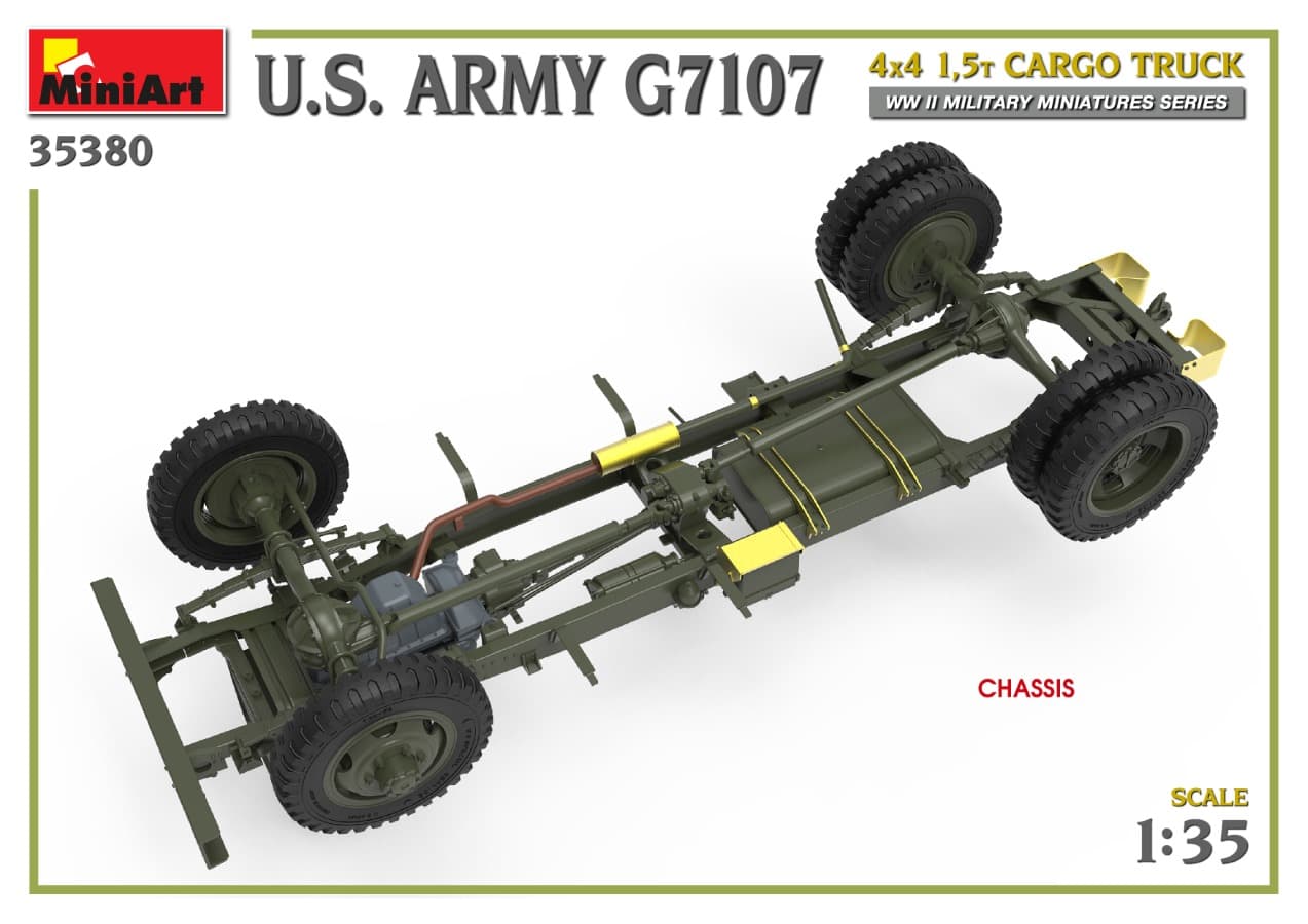
Replace the dual mounted wheels the drive housings from the Explorer
1 Like
Yes, I wondered about that too. This may just be a feature of the kit and not of the actual truck where the rear axle also rotates, or it does if you want the bogeys to move also.
My sense tho, is that you are likely correct, in that the axle is in reality, firmly attached to the leaf packs, and somewhere along the way is a bushing that allows the axle shaft and bogey assembly to move freely, but with diesel torque, load, and rough terrain, I’m still surprised there is nothing in place to limit axle wrap.
I added the torque arms because without having a way to attach the axle housing to the leaf packs it (the diff and axle housing) rotated freely - which I did not like. I modified mine some from the kit, as I ran a continuous alu rod from side to side, while the kit would have you use two plastic axle shafts, which I anticipated breaking.
I still wonder how they establish an upper limit to movement on the bogey, as there is no evident shock absorber, bump stop, dampener, or limiting strap? I should say, I sort of wonder as in the greater scheme of things - time to move on! ![]()
So on we go -
Cheers
2 Likes
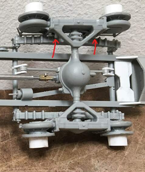
Total noob automotive engineer (you might as well ask me to dance ballet …)
would have put little bumps on top of (below in the photo since chassis is upside down)
the triangular arms on the walking beams. See red arrow, explaining with words would just
result in me getting tangled up in my own verbiage
1 Like
That’s it, i am going to sell all my kits and do something else. Brilliant work. ![]()
4 Likes
Well Robin, all form of self expression is beautiful…I suppose:

to each their own…! ![]()
Now, back to truly crucial business:
It looks like you’re right! there are indeed a pair of bump stops on each walking beam! And the leaf spring pack is very stout, so that might solve that!
I am not an automotive engineer either, but do have fun working on suspensions - I was hoping I could rationalize doing something like one of these:

Cantilever…while cool and able to operate independently, no!
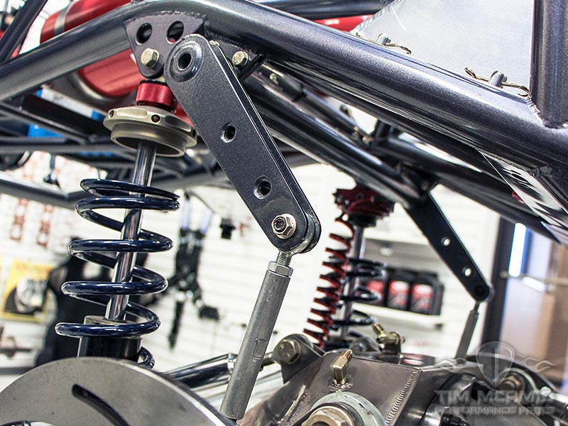
A rear stabilizer would look cool - except, each walking beam operates independently, which if applied here would no doubt get twisted…so, I’m sticking with the torque arms!
@Tank_1812, Ryan! no don’t sell your kits! Just feel good about cutting them up to make them what you want them to be! ![]()
thanks for having a look -
Nick
5 Likes
I Googled walking beam suspension and there is a LOT of different suspensions out there.
Modelling one chassis of each type could keep a model builder busy for quite some time.
The Explorer wasn’t the fastest truck around so high speed stability may not have been an issue …
1 Like
I know, right?? The shark has been jumped. I’m now graduating to Duplo block building ![]()
4 Likes