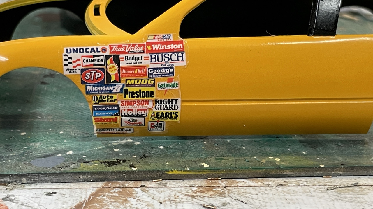
AMT/ERTL Kodak Olds NASCAR Start-to-Finish Build

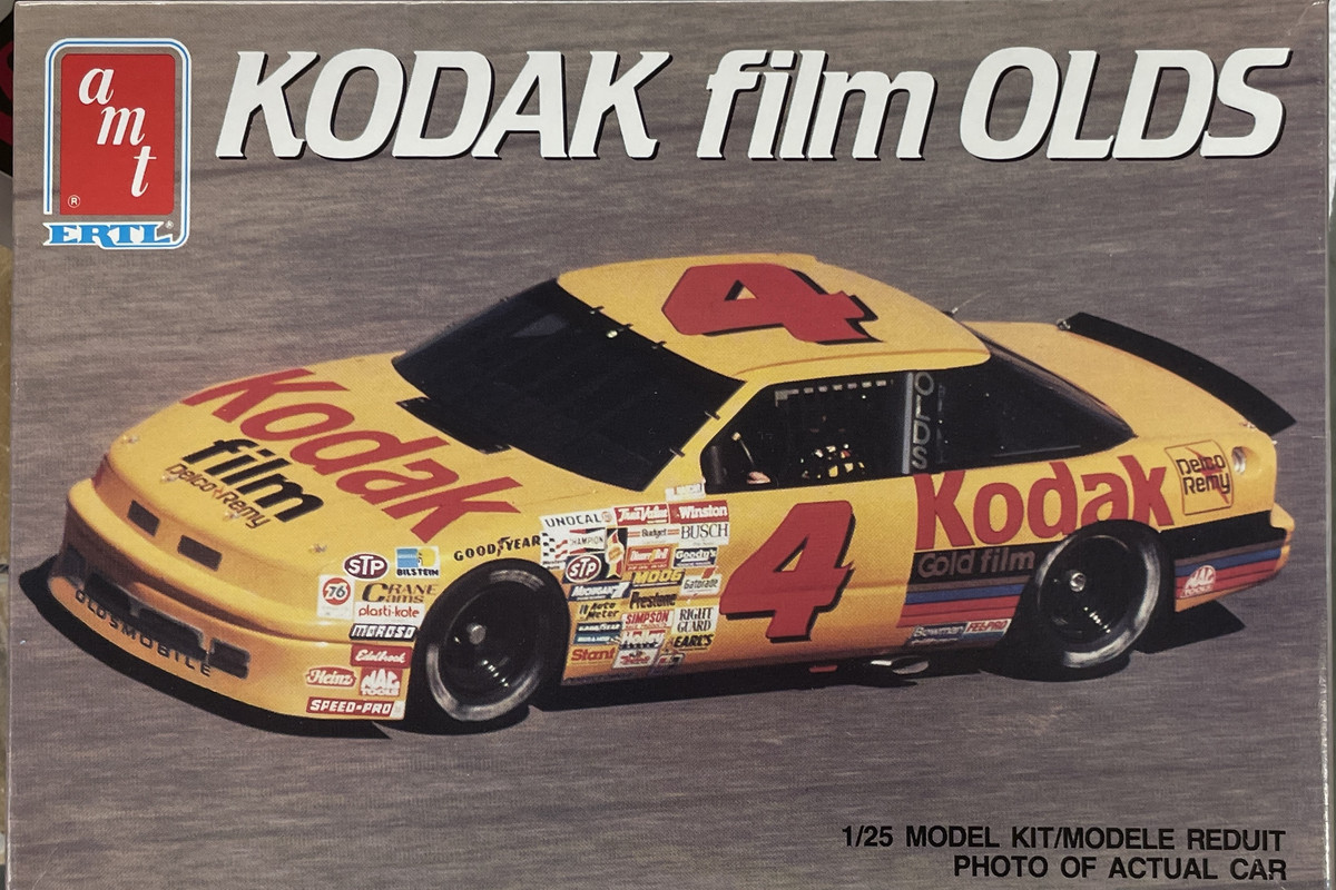
Our Louisville, KY model club, Military Moderlers Club of Louisville, is holding a mini-contest in July. The subject of this one is any kind of four wheel racing vehicle. I had won this AMT/Ertl Kodak Oldsmobile 1980s vintage NASCAR racer in one of the club’s usual end-of-meeting raffles. I generally don’t build cars since they don’t offer enough challenge for me, but with the upcoming contest, I will give this one a shot. I find that the older car kits just don’t have the brilliant molded-in details that modern kits by Tamiya, Meng, or Takom is currently producing.
As simple as some car kits are, NASCAR autos have no doors, no side windows, no grills, chrome trim, side windows… ergo, pretty simple bodies. Building the elaborate safety cage is somewhat challenging, but nothing in comparison to painting and detailing a normal car interior. Actually, the lack of complexity is somewhat of a relief since the last five years of modeling I’ve done are the most complex and sophisticated modeling I’ve ever done. My Iowa Tureet project is fully described in the Ships Forum of Kitmaker if you’re so inclined to review it.

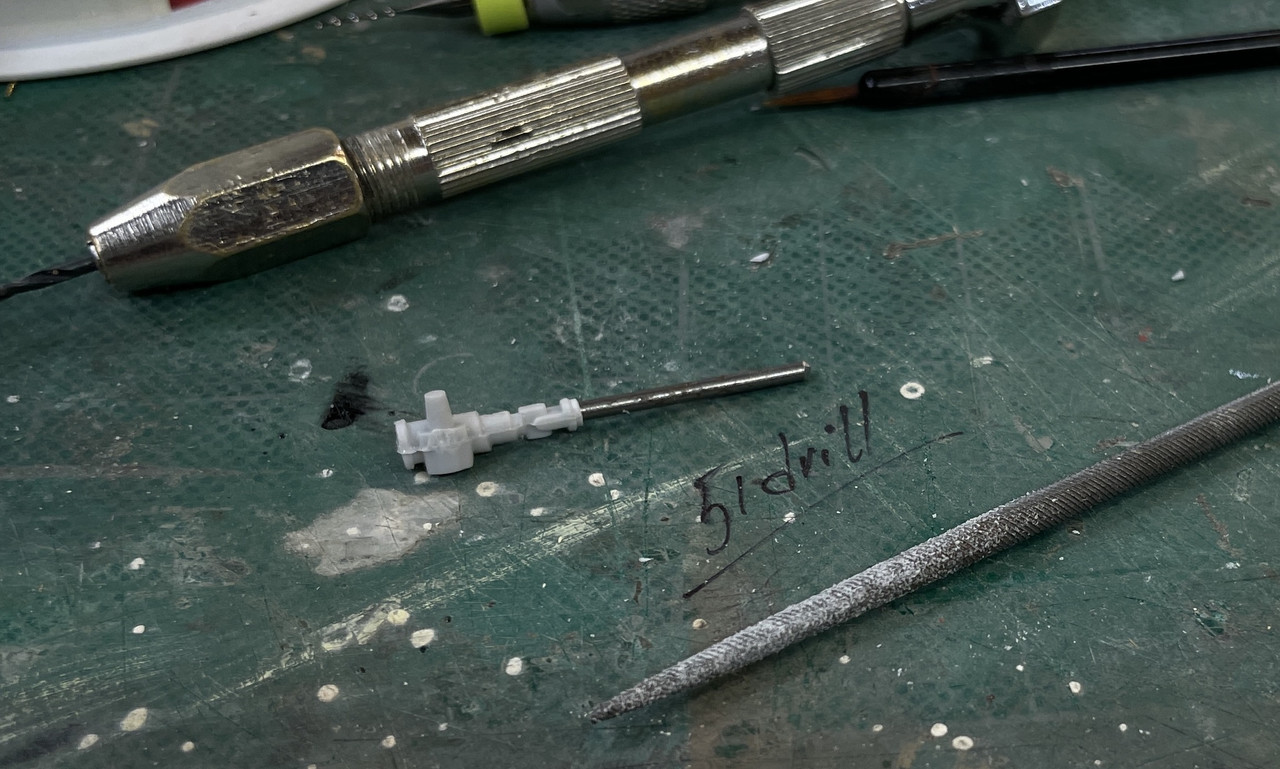
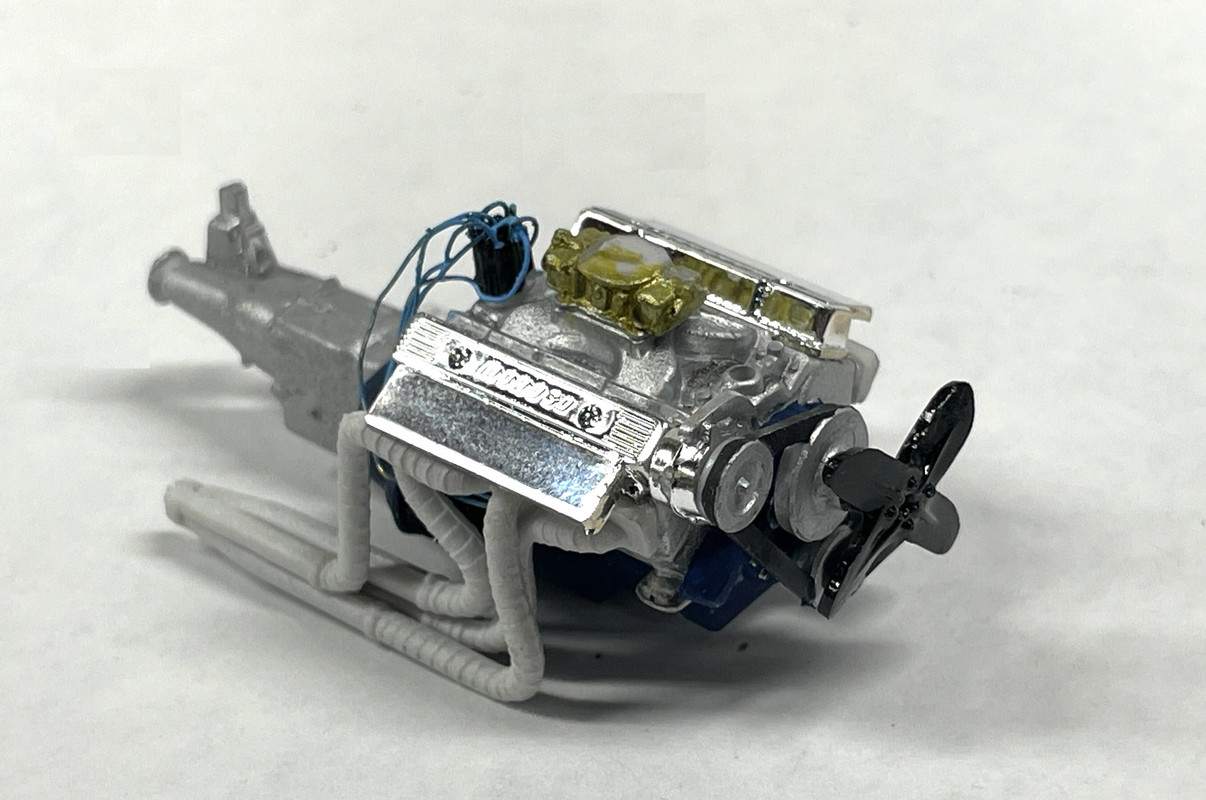
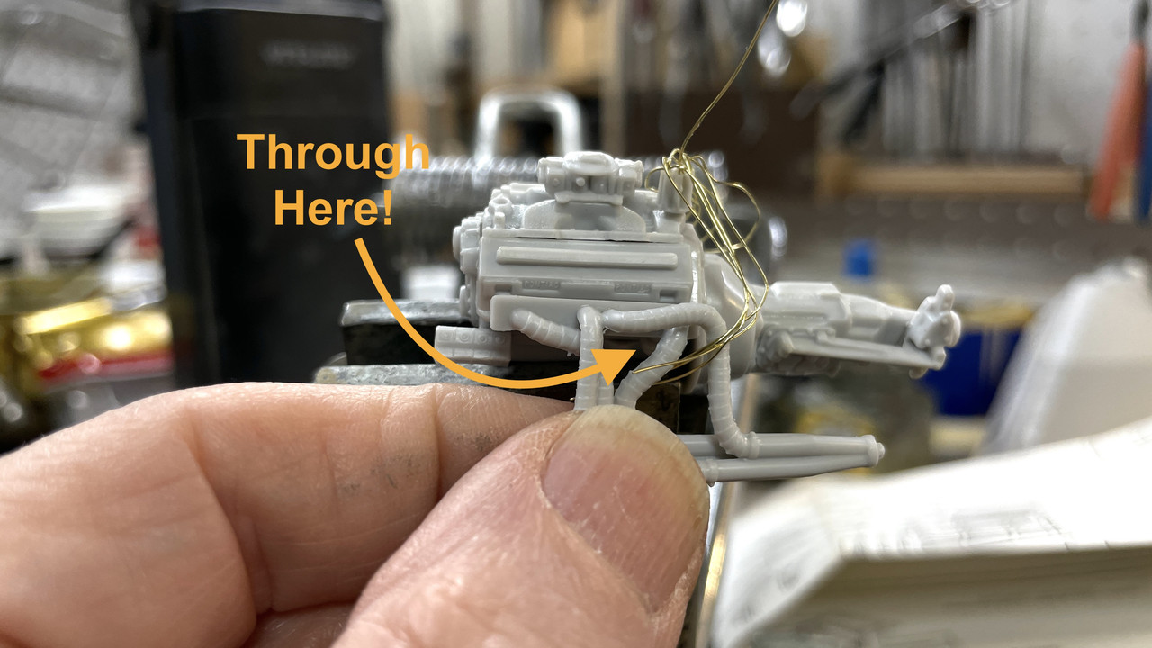
I already ran into difficulty in building the engine. The positions of the spark plugs is ambiguous and is partially blocked by the exhaust headers when they’re installed. I’m using some .012" brass wire into holes drilled by a similarly-sized carbide drill for the ignition wiring. I pre-placed all the distributor wiring. I’m not concerned about getting the firing order correct since I don’t know it. I am alternating them from left and right block sides.

The carburetor, while looking like a Holley, doesn’t appear to be correctly shaped for a NASCAR engine, nor does it have the spacer block beneath it and between intake manifolf. The contest winner will be determined by voting by the members and I doubt they’ll be that specific in their discernment.
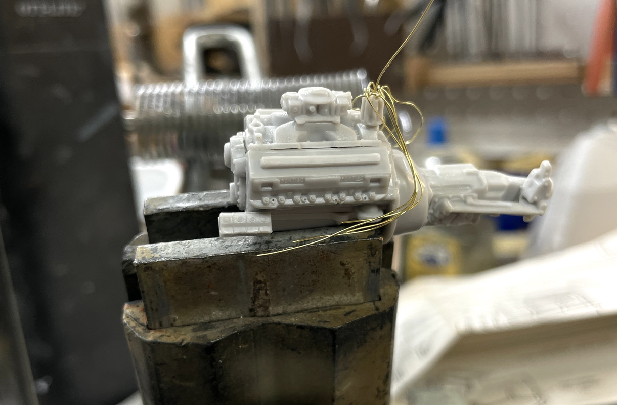
In this image, I’m holding the header near its final position and you can see that it obscures the access to those tiny plug opernings. Having to thread the plugs leads through the headers is why I haven’t terminated them into the heads. I have to wait until the engine is assembled and painted.
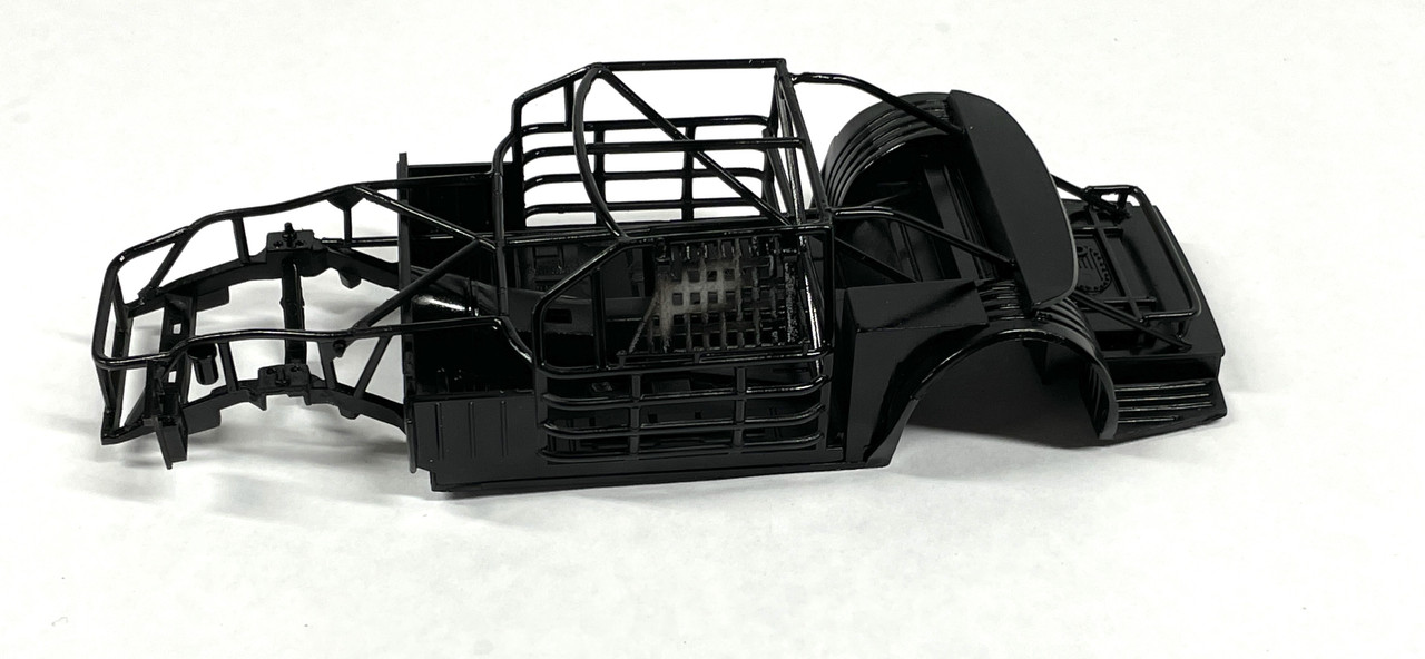
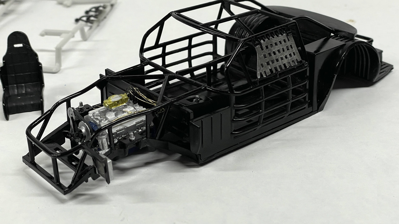
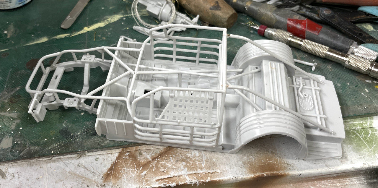
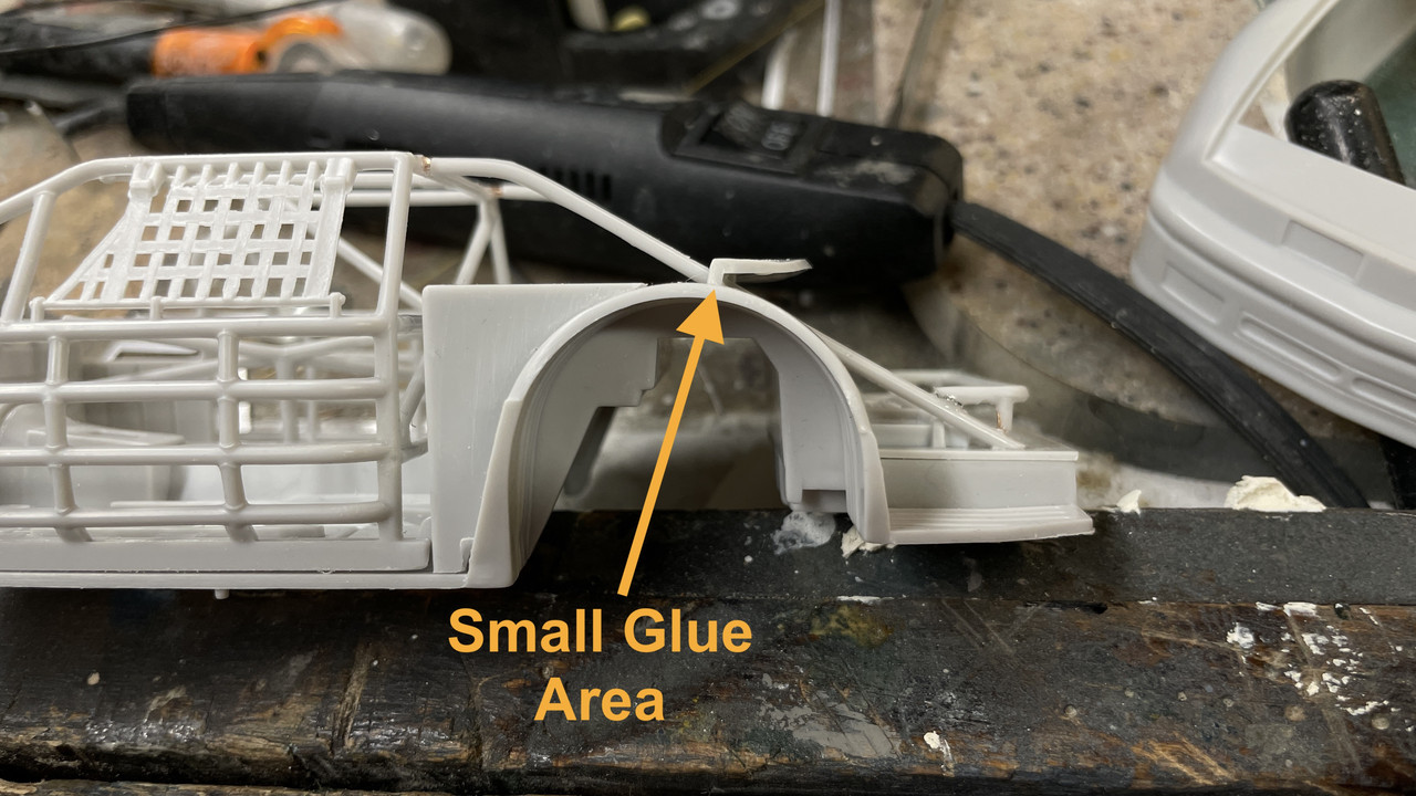
Leaving the engine aside I started building the chassis and roll cage. The entire assembly is gloss black so I’m assembling it all and will airbrush it as a complete assembly. I tested to make sure I could get the instrument panel and seat in place before doing this. Painting all this before assembly would just make a headache trying to get those tiny glue spots to fuse properly with paint nearby.
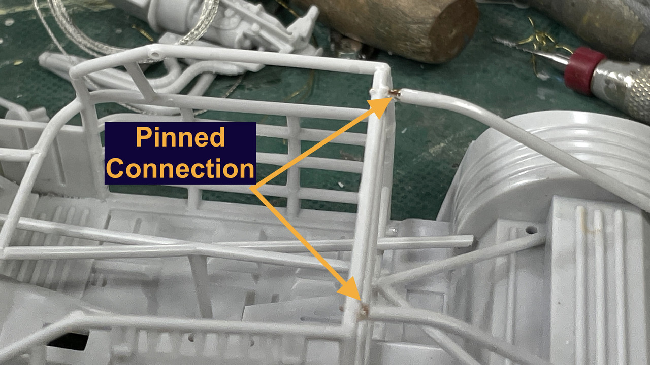
The rear angled members didn’t reach their final location properly and required drilling, pinning and CA’ing to get them to work.
So stay tuned to this short, not so complicated build. On deck will be something a bit more challenging: The Takom AH-64D Apache Long-Bow.

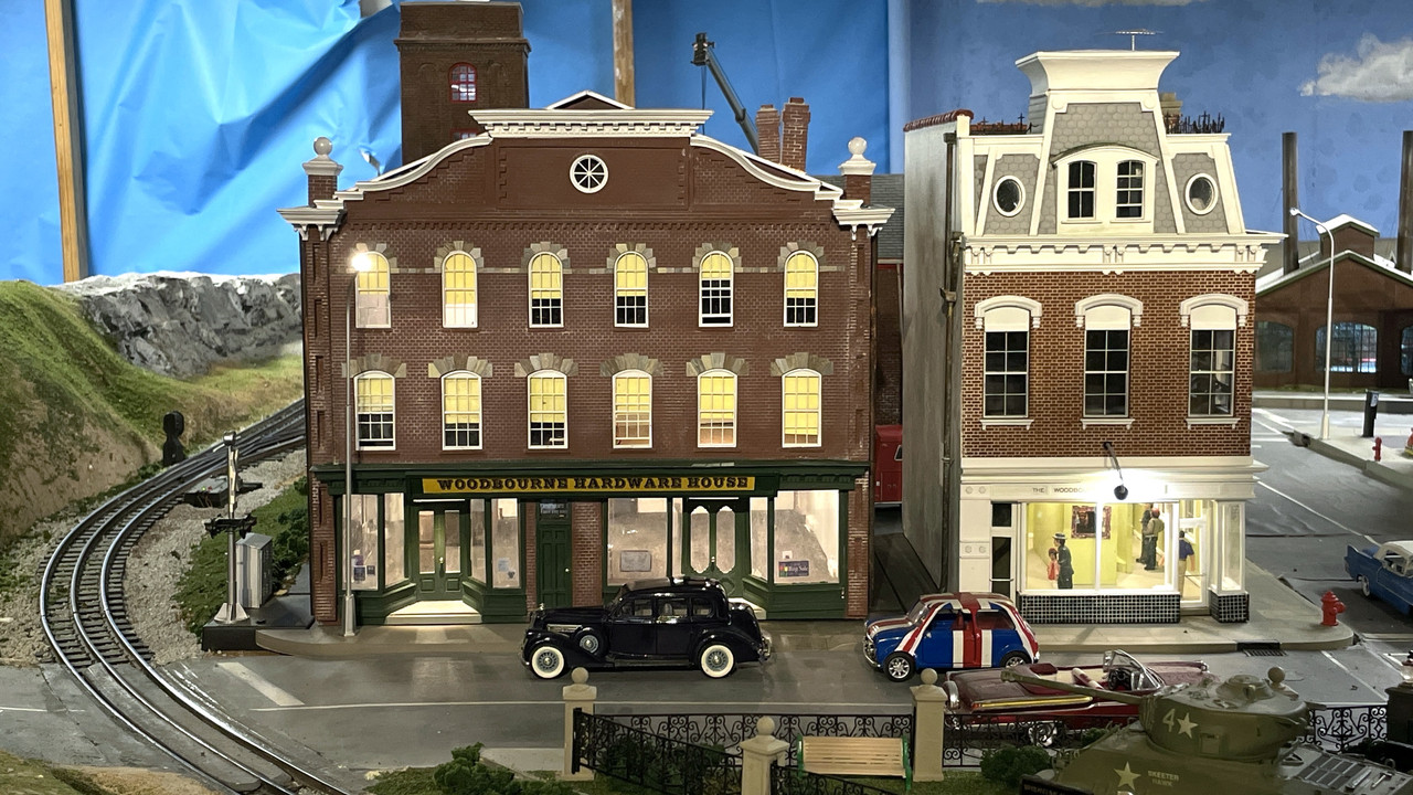
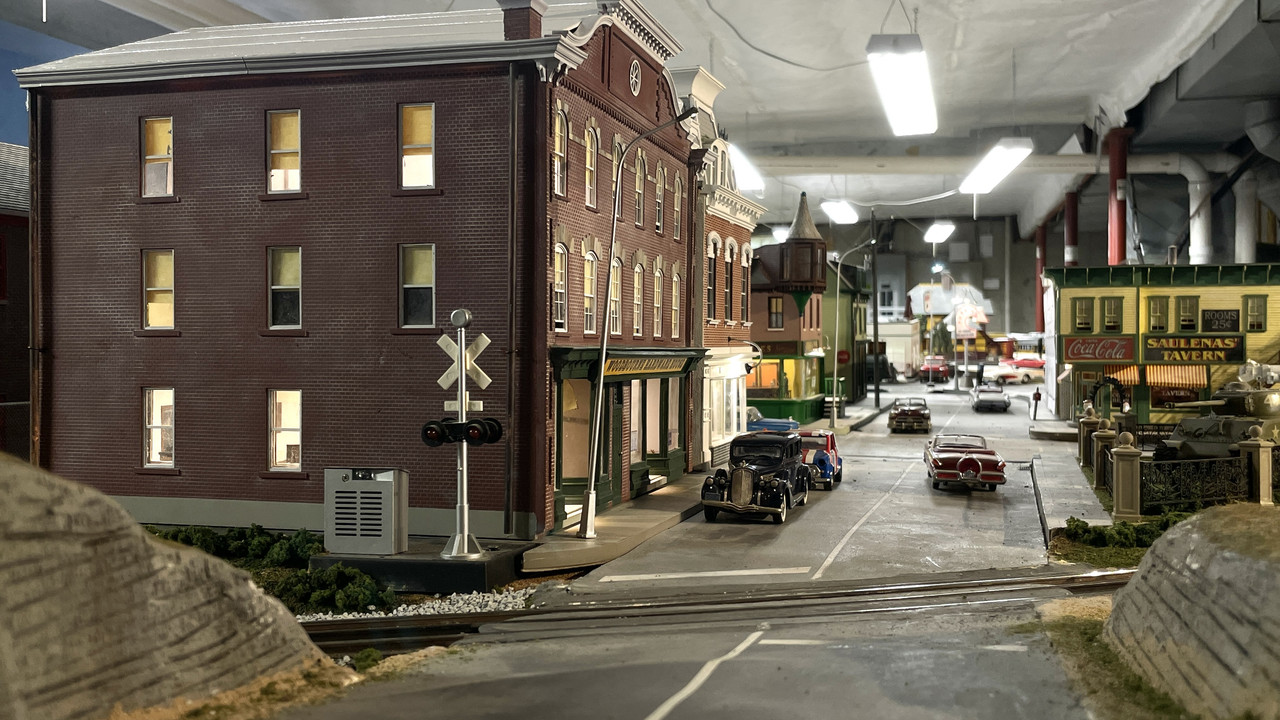
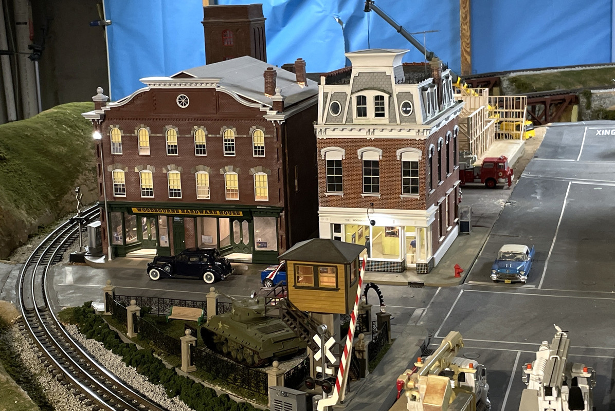
Just completed for my railroad empire is a replica of a 159-year-old hardware store that’s still functioning in Newtown, Bucks County, PA. I built it with help from the store owner and images gleaned from Google Earth. Flat surfaces are laser-cut 1/8" white acrylic cut for me by Twin Whistle Model and Sign Company. I produced all the 3D printed parts. All of this was drawn by me using SketchUp and CorelDraw.
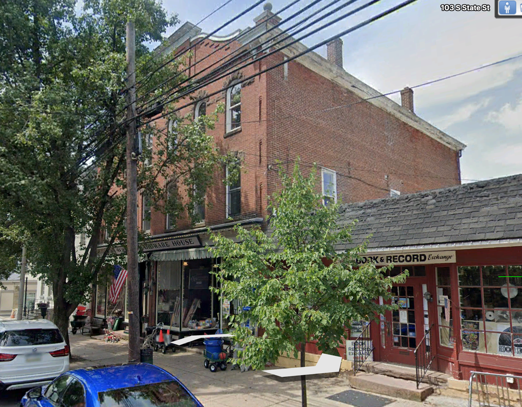
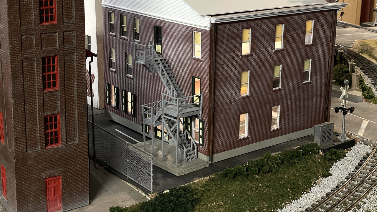
The real building has a very frail metal fire escape that would have been very difficult to model. I went with a scratch-built wooden stair.
And lasly it’s all lit.
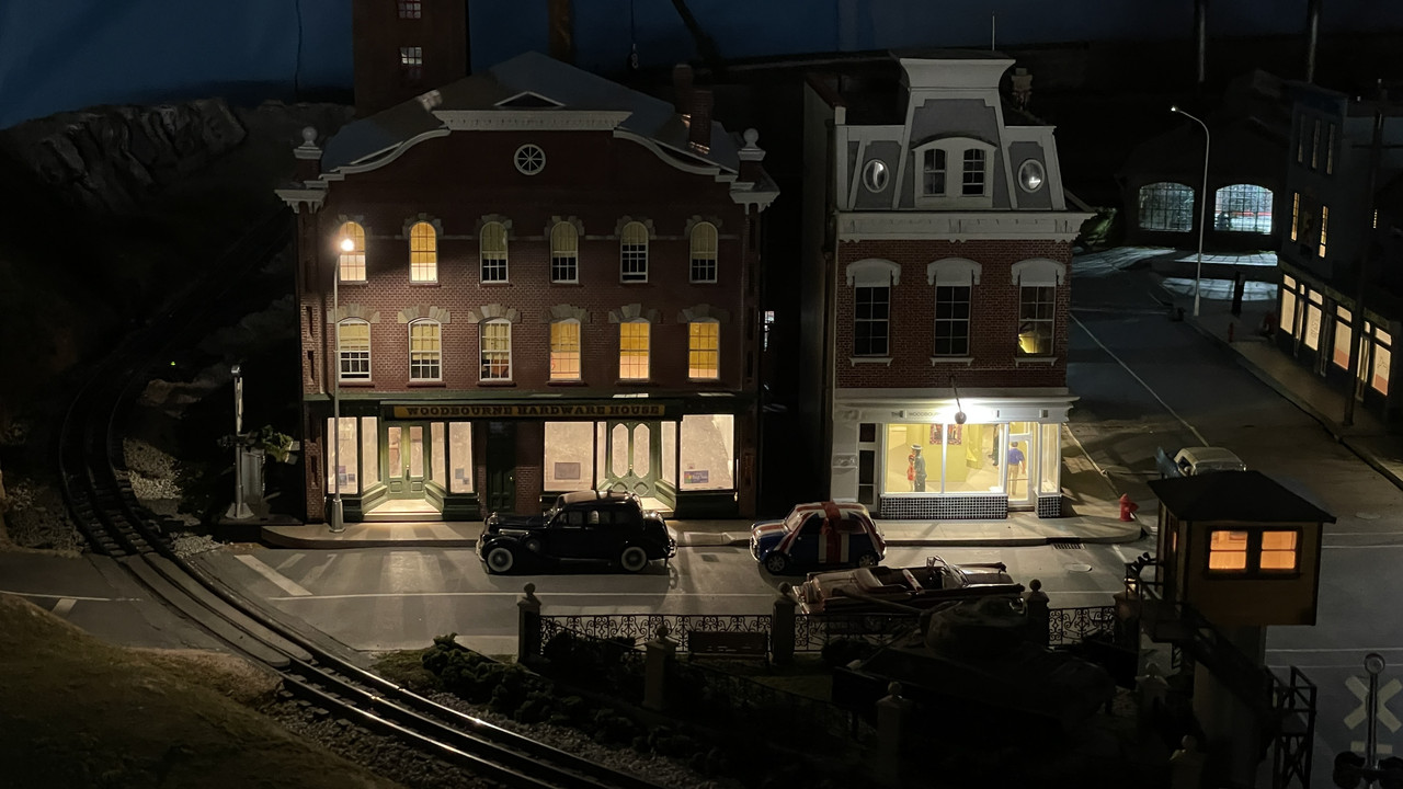
Missing is the interior detailing. I’m waiting on the owner to get me more pictures of the store on the left which is the main store. In the late 1800s, they opened up the wall and connected the two stores making a bigger hardware store.
6 Likes

Finished the roll cage, painted it and all the rest of the black chassis parts. I also cleaned up some mold lines on the body. Frankly, not having built car models very often in my later modeling years, I really don’t like the lackluster engineering especially after recently completing Meng and Tamiya products. The bar has been raised considerably and these old ERTL/AMT kits just don’t measure up.

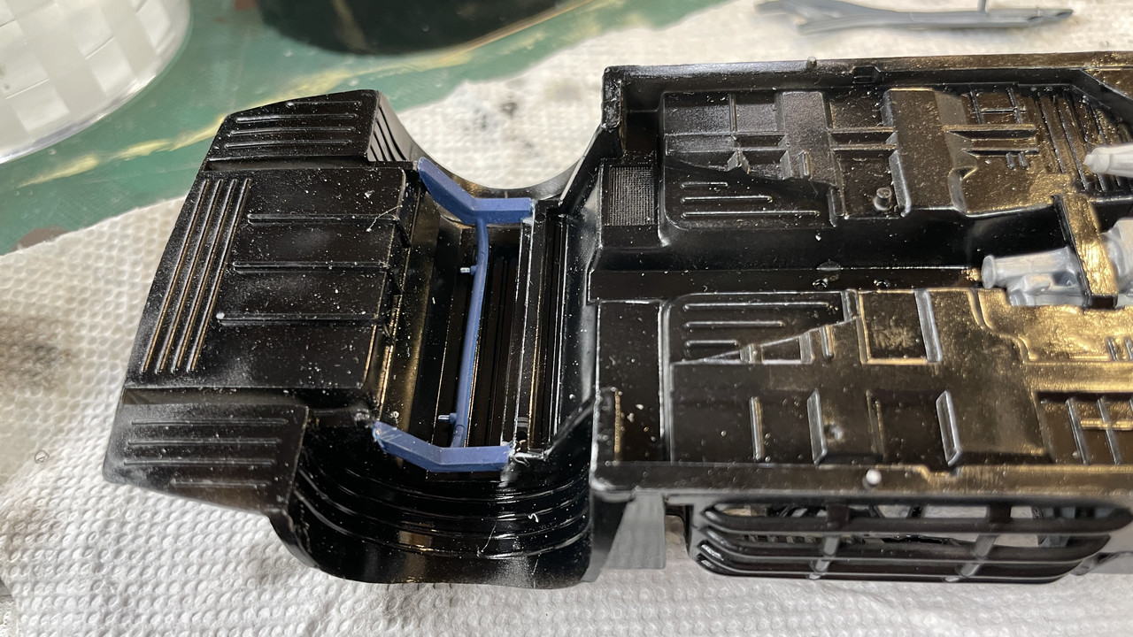
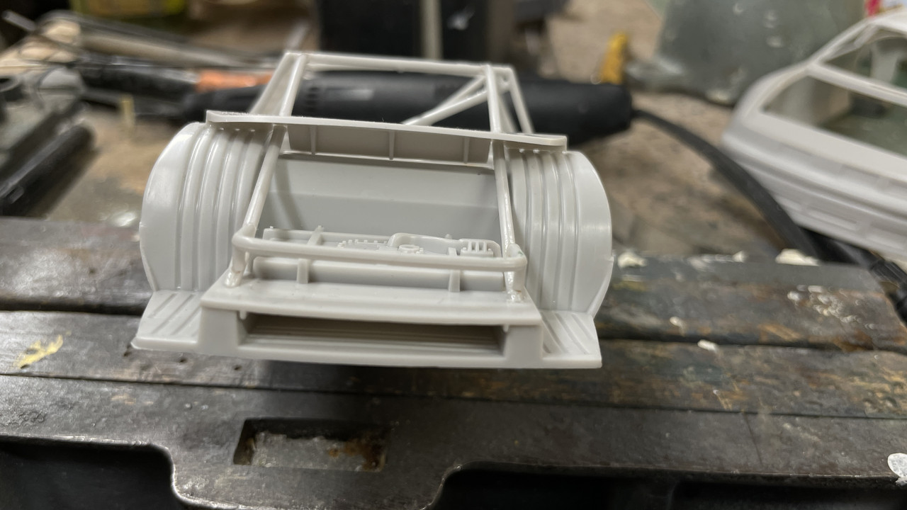
I did one more pinning job on the rear fuel cell guard rail. Again, very little gluing area and not-so-hot mounting pins vis-a-vis their respective holes. There is a rear plate that supposedly closes off the fuel compartment from the rest of the cabin. This part had no locating indexing. The drawing showed it glued to the apex of the rear wheel wells. I did it the best as I could. There were no notches, pins, bumps, etc. to guide and hold it. It just glues on a very narrow edge to the wheel well “sheet metal”, which itself was ridged giving and almost non-existent glue surface area. I ended up filling the bumps with med CA.

Here’s another view of that rear panel and where I put it. You can see how it’s just sitting on those ridges greatly reducing gluing area. It doesn’t contact the lower surface at all, further complicating the gluing.

When I test fit the body onto the chassis, that panel really doesn’t look like it’s in the right place.

When everything was glued and set, I airbrushed gloss black over the entire chassis with only the top of the firewall piece left out because I wouldn’t be able to install the brake/gas pedal part. I tested to see if I could install the seat with all the roll cage braes in place before gluing in the last brace that went down the upper center-line. I could get the seat in so I went ahead and glued in those last bits.

Next session I will paint the gray safety net when the black is fully cured. BTW: This is Tamiya Gloss Black.

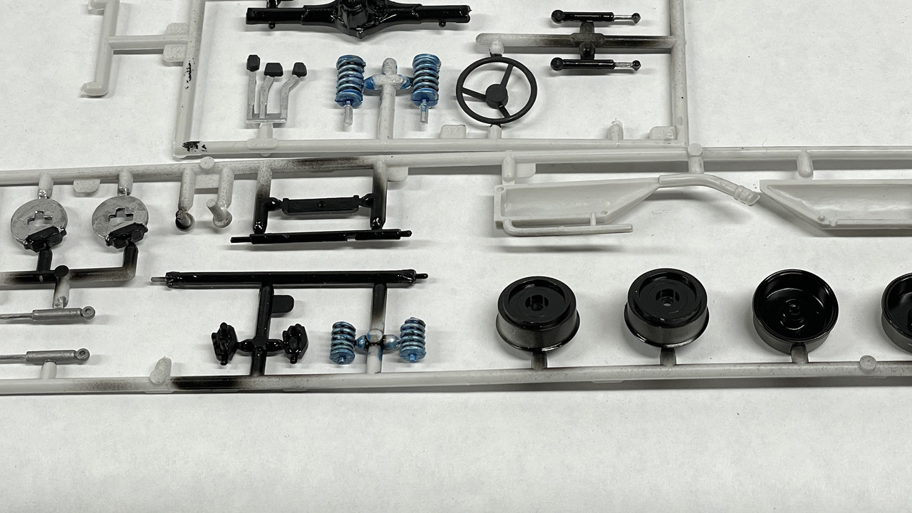
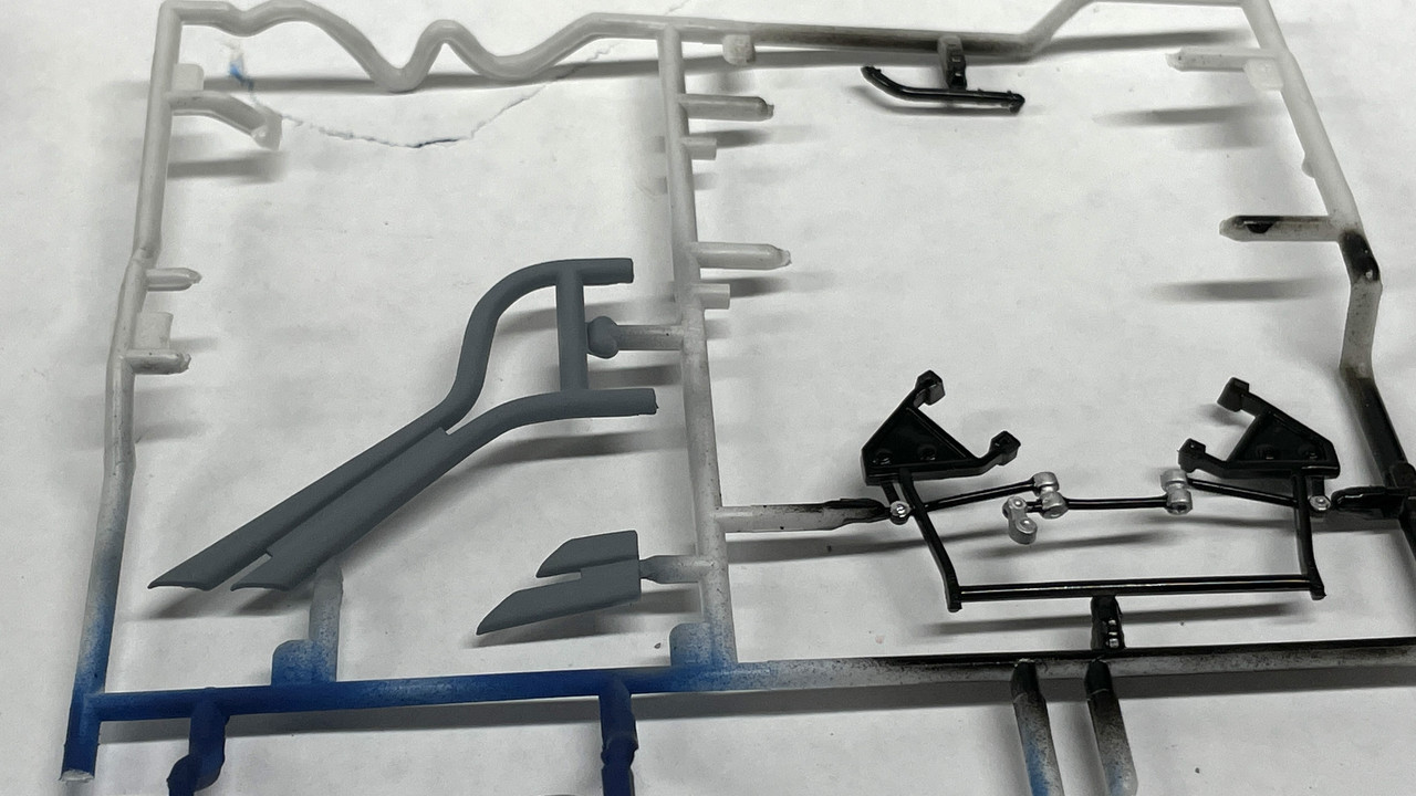
I also airbrushed all the black chassis components while they were on their sprues. I realize that this means touching up all the places where the sprue connectors were. So be it.
I substituted a piece of like-sized steel for the continuation of the steering shaft that connects to the steering box. It says to paint “steel”. What better way to simulate steel than using real steel. The two parts—real and plastic—are within 0.004" of each other with the steel being 0.059" and the plastic 0.054". As I used to say in my college R&B band when tuning up, “Close enough for Rock and Roll”.

There were some mold line misalignments at the front and rear “bumper” area. They aren’t really bumpers on Nascar racers. Reminds me of the Pixar movie, “Cars” where the protagonist’s girlfriend nicknamed him “Stickers” since he really didn’t have any headlights… Just graphics.

I was able to file and sand the front defects.

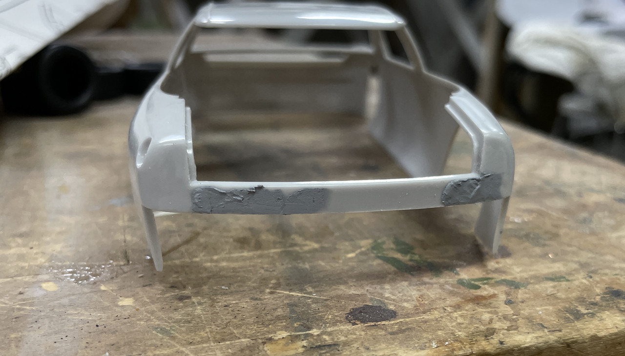
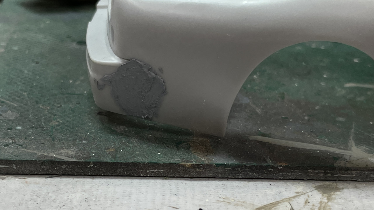
After sanding the rear area there were still some low spots which I filled with Tamiya Fine Filler and will sand out next session.

I made a test mix of the Kodak yellow. Straight Tamiya flat yellow is too yellow. Kodak seems to have a touch of red in it. I made a very small trial amount, but think it will work okay. I’m going to paint it with flat and then gloss it for the decal application. I’m not sure this is the best way to go. I could go with gloss yellow and red and be gloss from the get go. Thoughts?

2 Likes

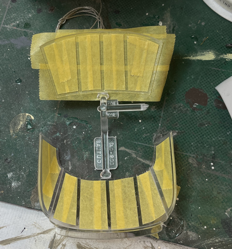
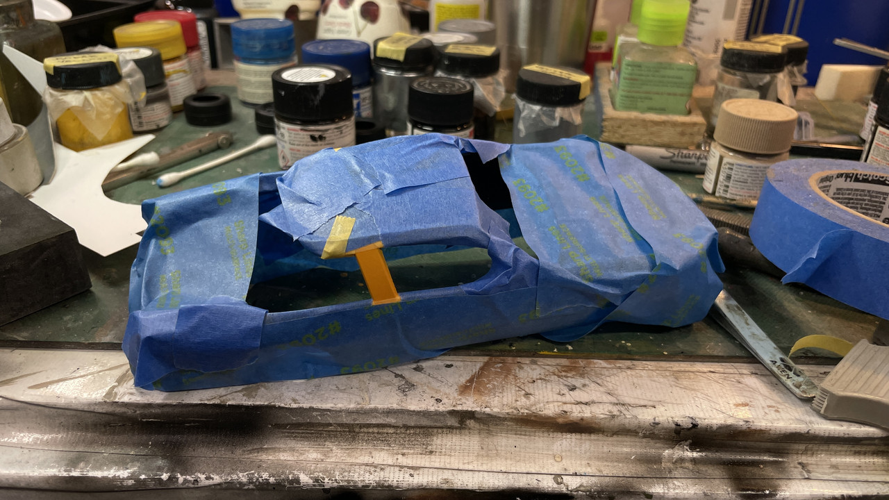
Yesterday was a painting day. First up was masking the reinforcing strips on the glazing. Who would think you’d have to do glazing masking on a MODEL CAR? The ribs were in relief on the inside which I don’t know if that’s prototypically correct. I used Tamiya tape, laid the tape to the rib edges and trimmed, then added the next strip and so on.

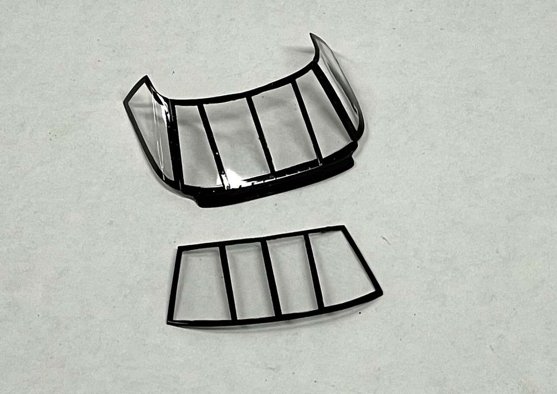
After airrbrushing with gloss black this is the end result. There were some tiny areas that needed some hand brushing to get it right.

The rest of the session was spent detail painting the parts I had painted on Tuesday. I wish the kit had instrument decals. I dry-brushed the gauge faces. I don’t know what these gauges even look like and don’t know what the background colors are. Right now the dry-brushing was silver. Nothing was note worthy enough to photogragh. I will takes some images on the next session.
Today is an exercise day which cuts my work time short.

3 Likes

I’m cutting and pasting this thread from the one I’m creating in Fine Scale Modeler’s Forum. I always do their’s first since inserting pictures in their forum is a pain in butt. You have to copy the pictures first to a photo service, then copy/past the URL into the “Add Images” dialog. However, to add the pictures here, all I do is copy the entire post from FSM and paste it here. A number of forums use this same engine and I’ve been know to publish on four different forums at once by copying just one post on FSM.

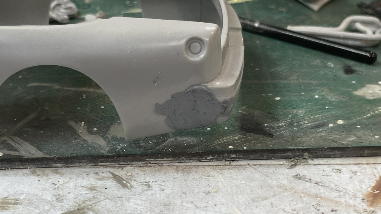
After looking at the prototype photos it’s clear that there was no seam between the rear (bumper) and the body which is how the front is. Therefore; I had to apply filler to both sides after sanding down the obvious height differences between the separate bumper part and body. I will sand out next session.

Lft side:

Rt. Side:

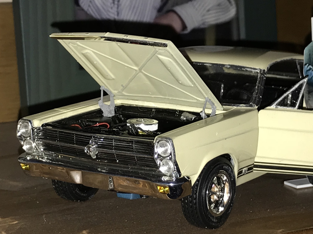
I then spent the rest of the session detail painting all the little bits. I’m so used to the new massive models by Meng, Takom, etc., that the simplicity of this one is almost boring. I used to churn out a model a week in my early teens since most of them were just like this one. And I’m doing it almost totally out-of-the-box, so I’m not fussing with superdetailing, PE or scratch-building. When I built my replica of my '66 Fairlane GTA I did spend a lot more time opening the door, detailing the engine including turning my own vacuum advanced for the carb, and making scale hood hinges. The hinges were drawn directly over pictures of real '66 Fairlane hinges found on eBay.

By their nature, NASCAR autos are much simpler beasts. They don’t seem to have hood hinges, fender walls in front, AC or power brake cylinders, etc., so no matter what, they are simpler to build. Oh… and they don’t have any doors at all.

After detail painting the engine I fit in in the chassis for this image. Note the shiny “chrome” lower part of the oil filter. I used decanted Molotow Chrome ink to give a very nice chrome finish by brush. Carb color is base Tamiya Flat Aluminum overcoated with Tamiya Clear Yellow. Belts and pulleys could be defined better…

Here are the rest of the parts: The coil springs would have been nice in real springs. The call out is steel blue. I painted aluminum with Tamiya Clear Blue overcoat.

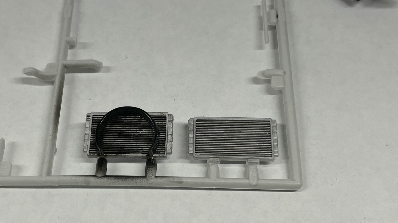
After painting fins aluminum I used Tamiya Black Panel Accent to fill in all the slats. I did the same with the oil cooler that’s slung on the frame in front of the front left wheel, and the spaces in the faux coil springs.

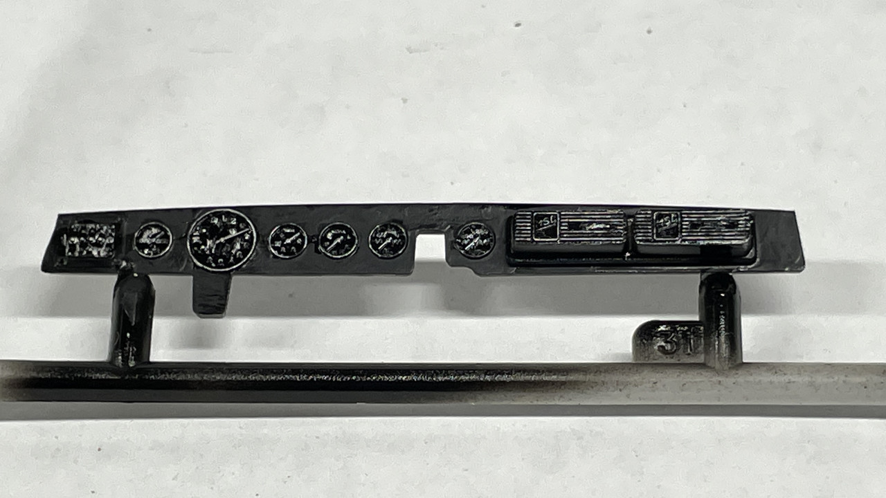
The crappy instrument panel is the best I could get it with the gauge faces glossy and the surrounding panel flat to differentiate the two. I like painting instrument panels, but I like them to give you more to start with. This is under pretty heavy magnification. Looks better to the naked eye.

I still have to finish that rear bumper and then paint the body. Then assesmbly will begin in earnest. A model in less than three weeks. Unbelievable. Compare that to 11 months for the Iowa Turret.

While sanding and polishing the filled rear bumper joint, one of them broke loose. The gluing surface was very thin. I reinforced the re-glued area with CA, and added more filler. When set, I re-sanded the area and worked it glass smooth with a series of polishing abrasive clothes starting at 3200 grit and going to 8000. As an afterthought I realized that I should have reinforced the joint from behind with some strip styrene. Oh well…

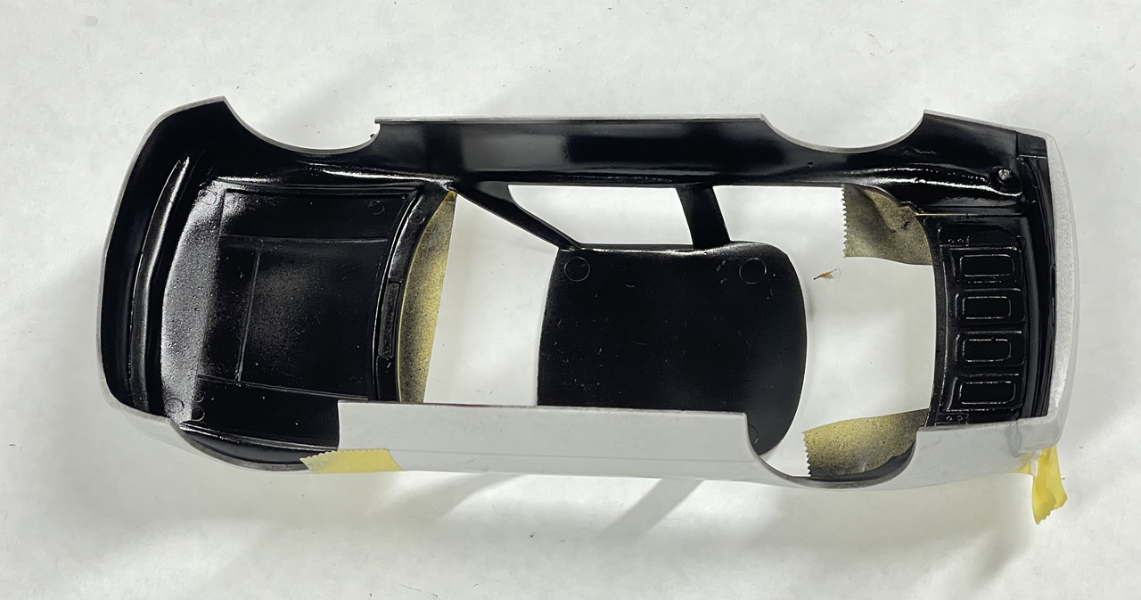
I then airbrushed semi-gloss black for the entire interior. To facilitate this, I taped the rear deck and hood in place from the outside.

When dry, I reversed the masking and masked all the interior openings including fastening the rear deck and hood from the inside. This was to keep any exterior color from fouling the newly painted insides. The instructions didn’t call out any interior color, but looking closely at the box photos, you could see that the insides were black.

I built the holder when I painted the Fairlane and kept it. Making your own tools is a good use of time.

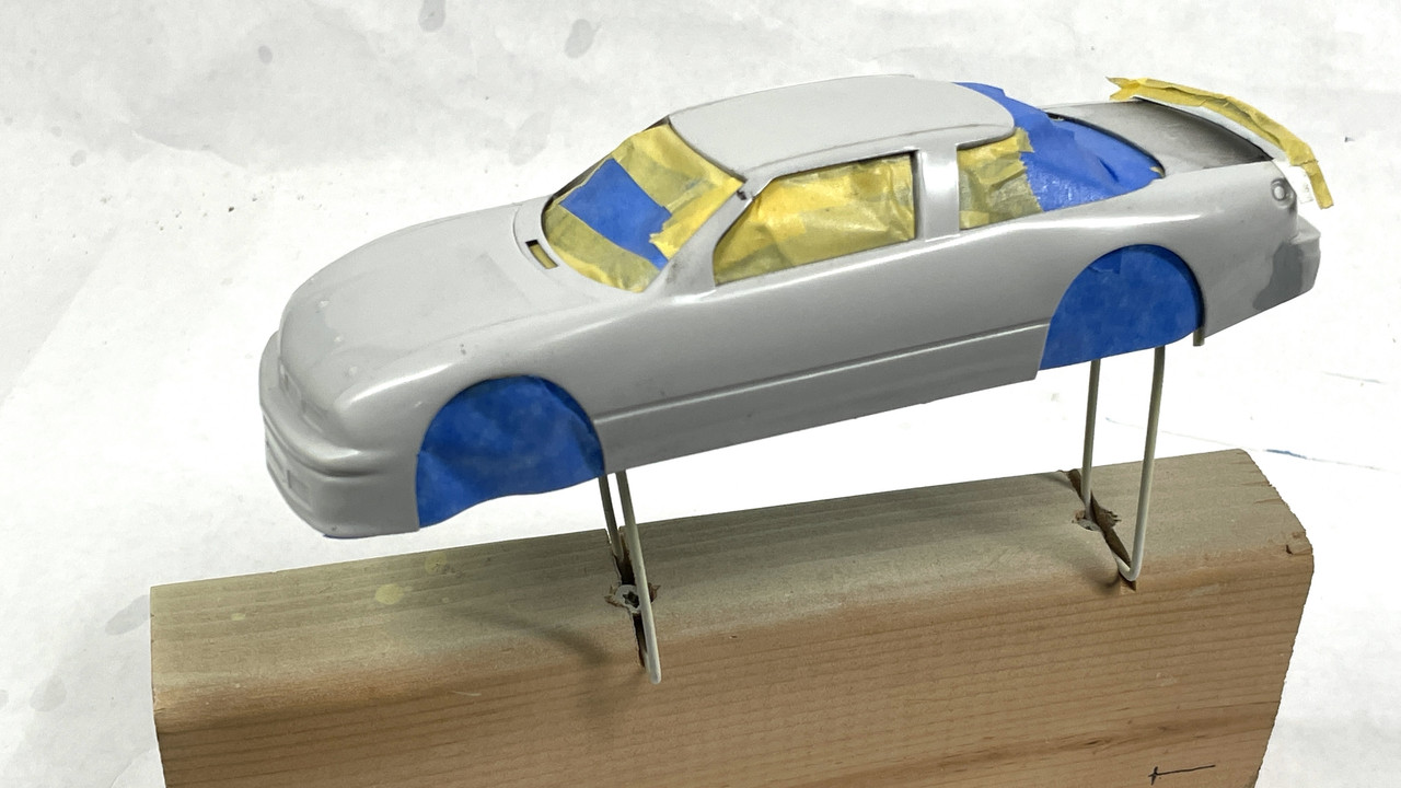
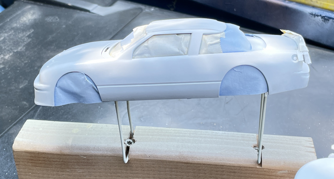
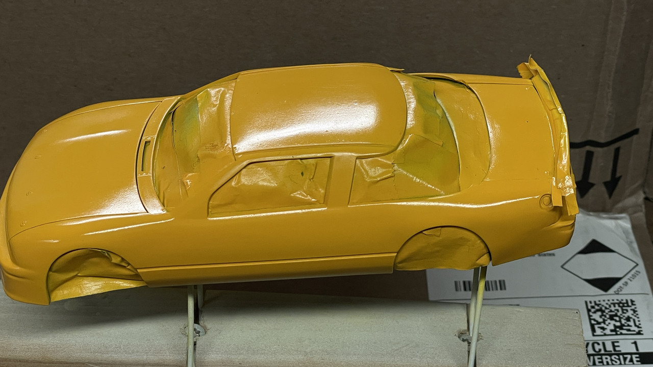
I don’t spray solvent-based paints inside, and the weather was perfect for doing it outside. My “spray booth” is the top of our trash containers. There was a slight breeze and I always do a wind check to make sure I don’t spray myself. I used Tamiya Fine White Primer. White is the necessary base color when you’re going to shoot yellow.

The blue is skylight reflecting on the white. Trust me… it’s all white.

The rear bumper blending worked out reasonably well. This will dry over the weekend and I’ll start finish painting next week.

While the body was drying I got the ignition wiring installed. I took the suggestion to just run them all under the exhaust headers. This worked. I painted the brass wires a more appropriate color. I don’t know where to run the coil line since one is not evident in the model. There is also a ton more piping on the actual engine than the model shows. I’m not going to worry about it. Many of the NASCAR engine pics online are of new engines, not as they were in the 1980s.

I also don’t know what weathering (if any) to do with the white headers. Like most multi-million dollar race machines. Engines and systems are changed regularly and do not age like normal mortals do. Drag engines are torn down and rebuilt every 30 seconds or so. NASCAR engines are probably pulled and replaced at the end of each race. That would probably include exhaust components also. I may be wrong here since I do not follow NASCAR regularly.

Next up is doing something with the fuel lines. These are braided. I bought some properly scaled braided line, but balked at the cost of the tiny metal fittings. I’m going to design and 3D print some fittings. Unfortunately, that must wait until I get my printer running again. The mother board/LCD input panel failed suddenly. Elegoo was nice enough to ship me new parts for no charge, even though I was out of warrantly for three months. It’s a Chinese company, but in my four-years experience with them I find them to make a good product and have very nice customer service. The new parts arrived yesterday and I will install them on Monday.

I also don’t have a clue about the throttle linkage and will do some research on the topic.

What is the best clear coat that’s also able to be rubbed out to high polish?

All the DADs out there; Have a happy and fun Father’s Day.

2 Likes

Interesting build, I have the kit but working on my Mack truck I need a break from Amt. As you said not Tamiya or Meng. The build is looking great. :+1::+1:

1 Like

Nice work on the NASCAR but I really love the old hardware store you did for your train dio. Glad they are keeping that historical store and building alive. :wink:

1 Like

The NASCAR look cool.
But that railway building… Wow !!! That’s impressive :+1:

2 Likes

Thank you! If you have some time on your hands and would like to see all the railroad stuff I do, please check out this link.

I’ve been posting a continuous thread on the layout’s construction since 2013. It covers literally every aspect of the project including table construction, track laying, wiring and controls, scenery and landscaping and ALL structures. My early buildings were commercial kits, but almost all for the last six years have been custom like the Hardware House.

3 Likes

Looking good. I think you’re trying to say it’s not as worthy as a Meng or Takom kit. :slight_smile:

For me, that’s the appeal of those older kits. As with older armor, you can really make dramatic improvements with little effort. I’ve built a few NASCAR kits for folks over the years. The dashes indeed leave a lot to be desired, but there are PE and acetate replacements that have several arrangements to suit your needs. I’ve also used very short pieces of aluminum tubing to go around the gauges. Like you said, nothing beats the real thing when it comes to metal.

I’m actually more interested in that structure. Do you know what hapenned to the upper story of the building on the right, or is it a whole new buidling now? The top of the facade is the most striking part. Looks like you nailed it.

The building on the right… I modeled it from a single image in the New York Times and then finding it on Google Earth. It was 3D modeled in Google Earth so I was able to determine what the unseen sides looked like. In real life it’s a 2nd Empire townhouse built in the late 1800s. It was falling apart and ressurected in the 1990s. It’s is now the Bronx Conservancy building with an art gallery on the main floor. After drawing it, and making a cardboard mockup, I found it was too deep and a little too tall to fit in with my modest village so I chopped off about 15’, gave it one chimney instead of two and removed the 3rd floor maintaining that terrific ornate roof.

This was the NYT photo.

This was my first drawing attempt:

And the modified ‘selectively compressed’ version. Like all of our modeling projects, we’re always making compromises from the real world to (in this case) our 1:48 world.

I use SketchUp for my 3D drawing taking advantage of their “Match Photo” feature which enables you to draw in 3D over a 2D image. The trickiest part is setting the initial scale. I usually use a door height to set it. But door heights do vary so my scales could be over or under-sized from the prototype.

It was my first model to use 3D printing, which I had done by an outside vendor to my drawings. I now do all my 3D printing in my shop. The walls off both of these buildings were laser cut by outside vendors. That’s a tech that I now want acquire with the advent of solid state laser cutters dropping the price.

1 Like

Myles great to see you back & in an unexpected (to me) new project! As has been said, stunning railroad & buildings, looking forward to seeing how you ace the Olds :beers:

I’m always surprising people. The model club has this raffle at the end of the meeting where guys put up their unwanted kits. Plus the owner of our fabulous hobby shop and club founder always adds his own stuff to the pile. Most of what I keep winning are models I would not buy, but occasionally I get one that’s worth building. With the up-coming race car contest, this one made sense.

2 Likes

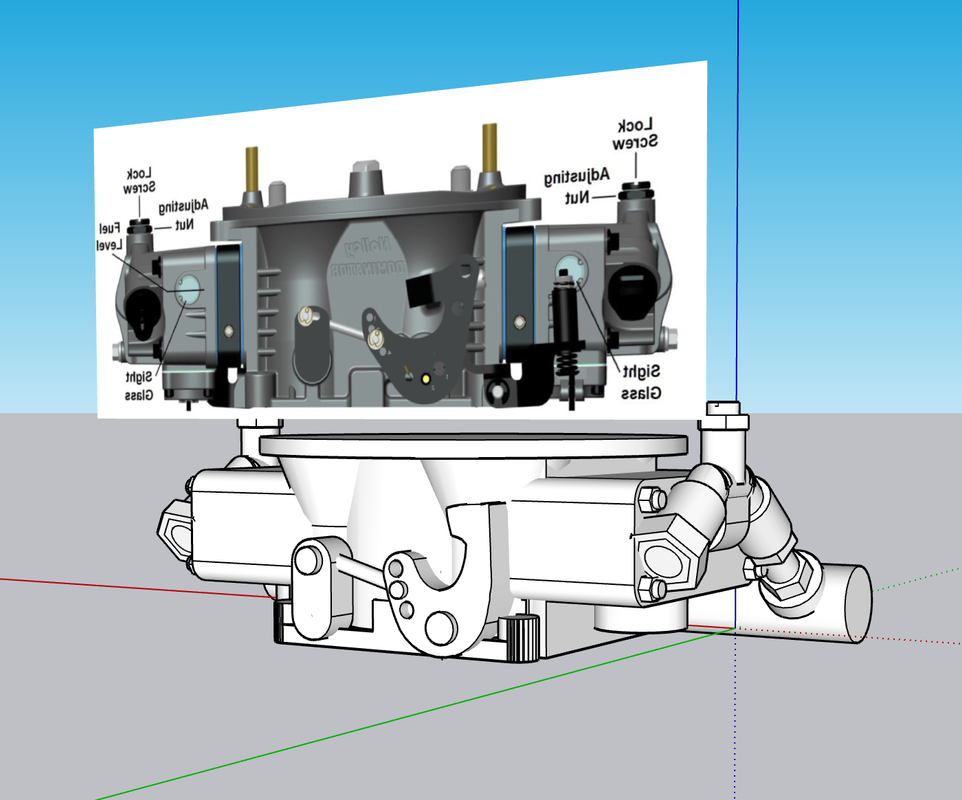
With my 3D fully functioning again, I was able to make some customer plumbing fittings and a big ass Holley Dominator Carb that looks a whole more like it means business that the pitifully undersized one including in the kit.

While the carb seems really large, I was able to download images of the carb from Holley’s website and the bolt pattern. From the dimensions on the bolt pattern I was able to scale the entire unit. This is how it looked in SketchUp where I drew the carburetor. It’s just a big carb.

![](With my 3D fully functioning again, I was able to make some customer plumbing fittings and a big ass Holley Dominator Carb that looks a whole more like it means business that the pitifully undersized one including in the kit. While the carb seems really large, I was able to download images of the carb from Holley’s website and the bolt pattern. From the dimensions on the bolt pattern I was able to scale the entire unit. This is how it looked in SketchUp where I drew the carburetor.)

Here’s the complete drawing in SketchUp. It’s not a perfect replica, nor did it have to be. Besides simply being so small AND being partially hidden by the air cleaner, the level of accuracy was sufficient. I also took the liberty of adding the fuel manifold with a pipe fitting on the end for the braided tubing to reduce the level of fussy scratch-building I would have to do.

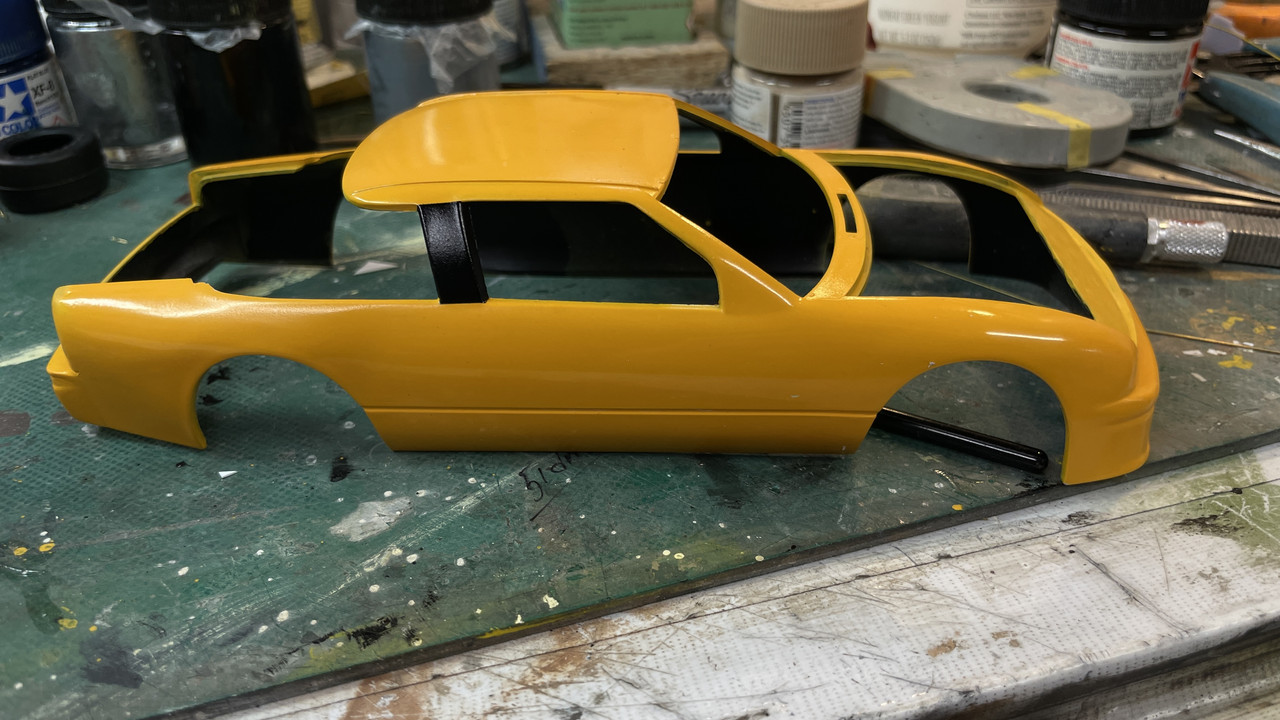
I got the 2nd coat of Alclad Aqua Gloss after a light sanding with 4000 grit.

After polishing the 2nd coat with 6000, 8000 and 12000 grit plus Novus Plastic Polish I’m declaring it shiny enough for a race car.

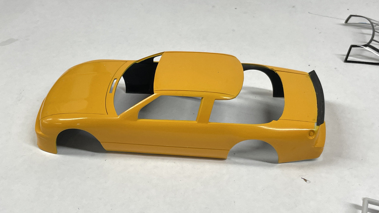
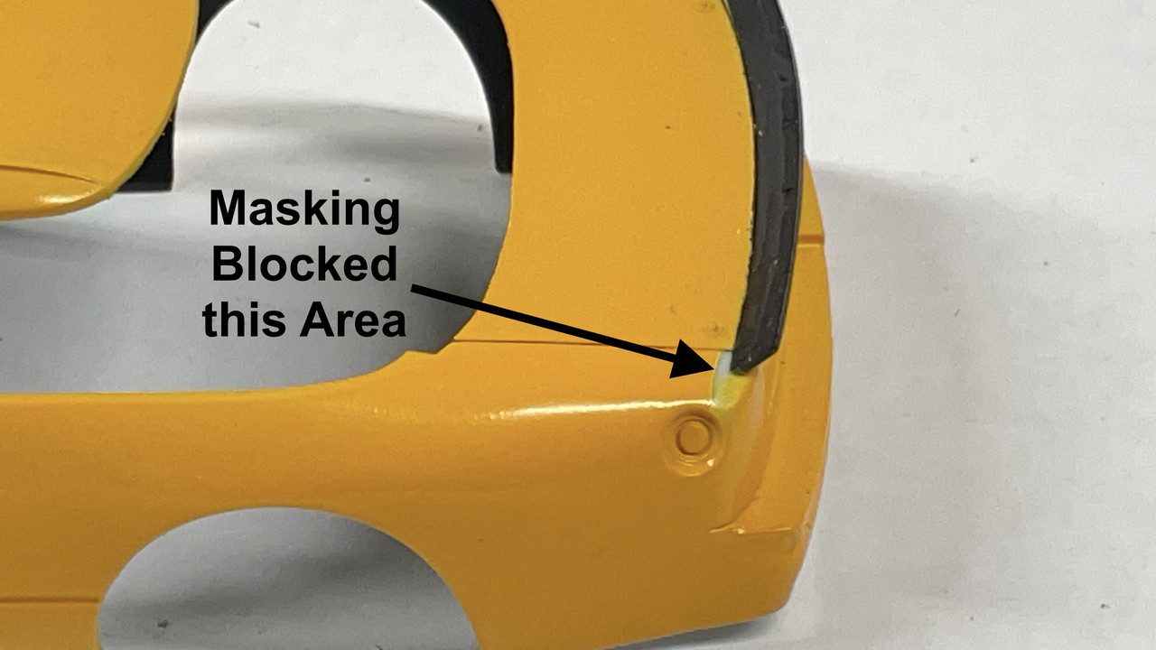
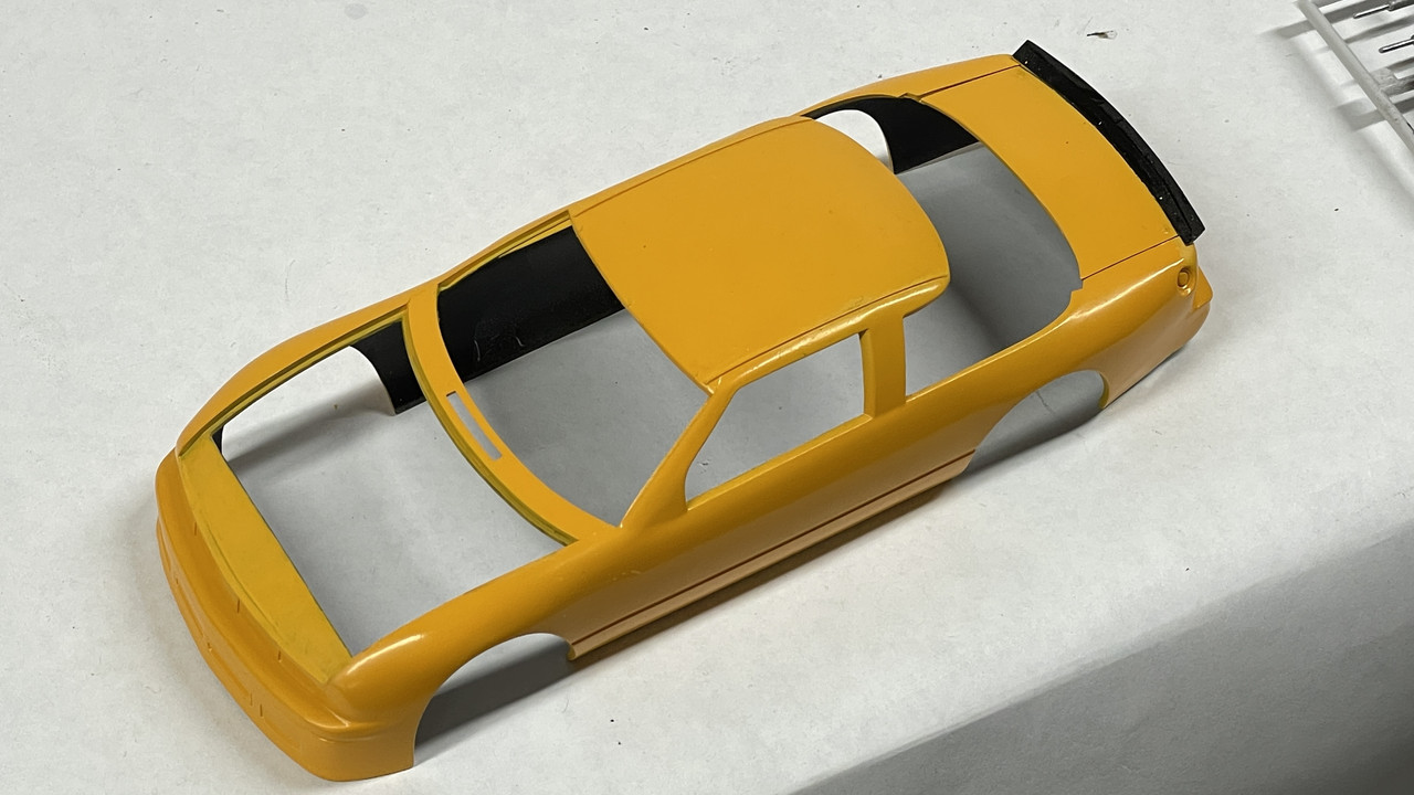
After pulling off all the masking I found that I made a booboo. I SHOULD NOT have painted the hood and trunk lids attached to the body since it hid areas that needed to be body color. This was evident on the hood and trunk edges and more importantly, on the panel that covered over the radiator.

Futhermore; the masking on the spoiler covered part of the body in the back corners.

I touched these area by hand. Remember, my base color is a mixture of Tamiya Flats so the area in the rear is going to need some gloss. Annoying!

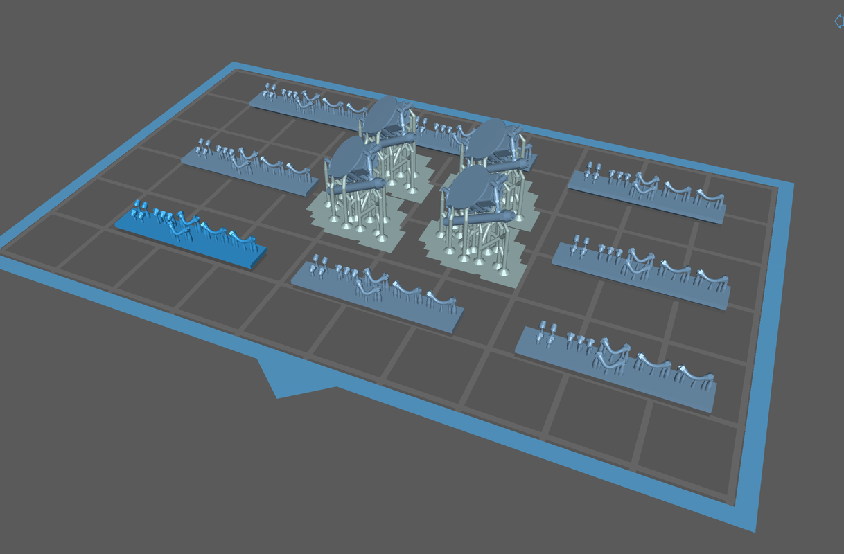
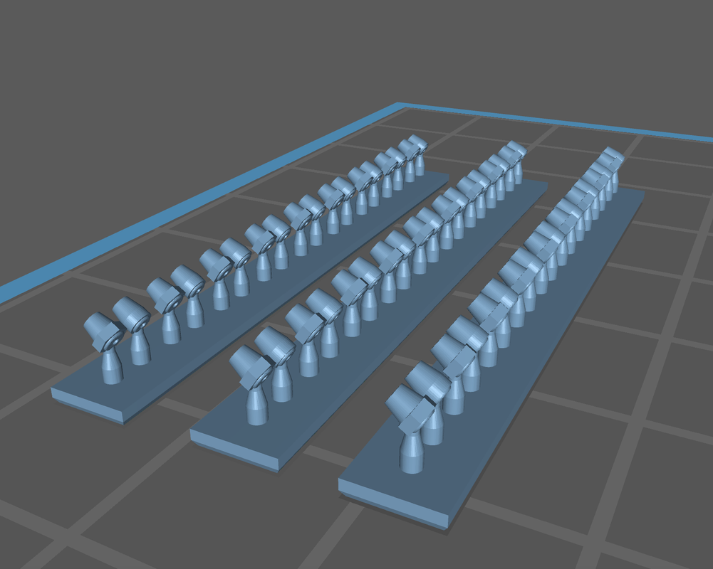
I also printed the plumbing fittings. Here are the carbs and fittings set up together on the machine. A reminder: Unlike a string (FDM) printer where the amount of material on the building surface affects the print time, here you can load the plate up since it prints everything in one complete layer at a time. What directly affects time is the height of the part, the thickness of each layer, which in this case was 30 mircons, and the exposure time for each layer.

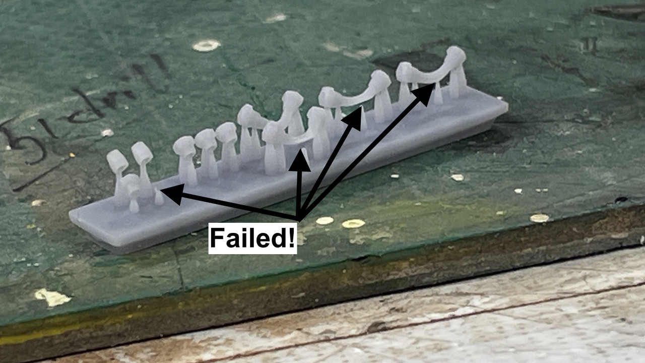
I always print many more parts than I need. There are ALWAYS failures.

My first attempt on the pipe fittings was successful, but they were just too small to handle and get the braided tubing into. I redrew enlarging the opening a tad and the over size about 130%. This printed by failed.

Reason: I drew these supports in SU and made them just a bit to fine. The supports failed to hold the parts intact as each layer was lifted to bring in fresh resin for the next one.

Back to the drawing board. I added more meat to the supports and will print again on Monday.

The carbs did print successfully. I trimmed one and post-hardened the whole batch. Of course the glue joint holding the original kit carb on the intake manifold was unbreakable. I had to resort to some pretty hefty flush cutters to cut it off. I had to sand its remains off the manifold and then glue the resin one in place with medium CA.

Notice there is throttle linkage which I can hook up to the rest of the car if I so decide.

Other view showing fuel manifold.

Onward and upward. See y’all on Monday. Have a nice weekend.

6 Likes

Happy Monday.

I changed out the LCD print screen protector on my Elegoo Mars 3 3D printer. The factory standard one was a piece of some kind of film that got scratched in several places. I thought it was tempered glass and was wondering how it got scratched so easily. Instead, being film,e it scratched when I wanted to scrape off some hardened resin. The new protector is tempered glass and should hold up well. The packet came with 3 so I have replacements.

I was then able to print the redesigned plumbing parts successfully.

Before getting down to that work, I had to paint one more thing on the body… the black panel on the mid-door pillar. I masked the heck out of it so no black got on any yellow.

I airbrusded the gloss black and then demasked. Not great, but should work. There’s an “Olds” decal that goes on this pillar.

My strengthened supports enabled the plumbing parts to form properly. That said, they’re really, really little, and the getting the braided hose into them is almost an exercise in futility.

I’m using 0.022" phos bronze to provide the connections between the fitting and the engine. I had to drill the tiny openings on the fittings slightly larger and deeper. This is painstaking and a little frustrating work. I am persistent to a fault.

First was putting the fittings on the separate oil pump and the crankcase oil sump. At first I attempted to put the fitting on the metal and then fit this into the holes in the engine. Wasn’t so hot. I then reverted to puttting the metal pins into the block and gluing (med CA) the fitting to these little metal stubs. Worked better… not great… just better.

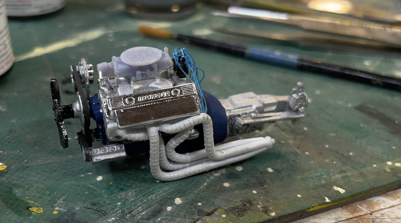
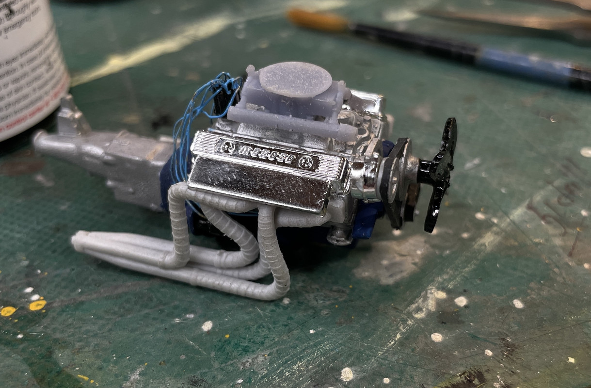
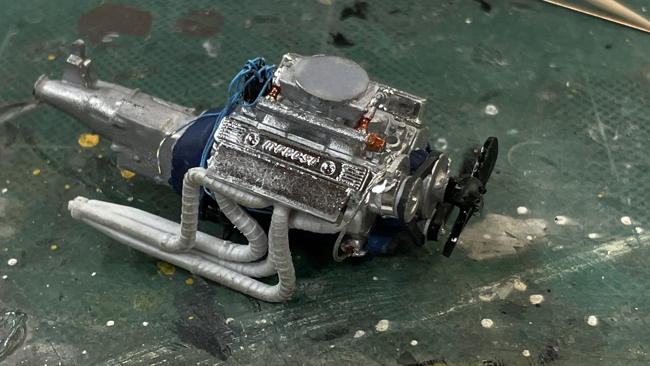
I got the all installed. Notice that the exhaust manifold on that side is off the engine. It was blocking working on the pump. But that’s not why it broke. Seems that attempting to fit the engine into the chassis with the pipes on AND the firewall in place put a lot of stress on the headers and one broke loose… the oil pump… which was fortuitous since I needed that one off anyway to do this piping work. I was fitting the engine to check the air cleaner clearance. I had to put some packing under the cleaner so it would sit firmly on the new and much larger carb. It fits, but the hood probably will not fit right. I’m going to display with the hood off, so no harm no foul.

And then it was time to try and get the braided piping into place. Took a while to get this first one. The plumbing fixture’s holes are very deep and the braiding just barely enters. Lots of CA!s

Now that I look at it, I realize that I didn’t install the compression fitting on the braid end. I’ll pull it off next session and get it right. It’s the first time I’ve ever used miniature braided piping and it’s not easy especially at the 0.020" size.

I use a mix of 80% Elegoo ABS-Like standard resin and 20% Siraya Tenacious flexible resin n to toughen up the finished part. It’s really important. These little elbows are quite tough and I didn’t break any of them in their narrow part even though I was treating them a bit roughly.

4 Likes

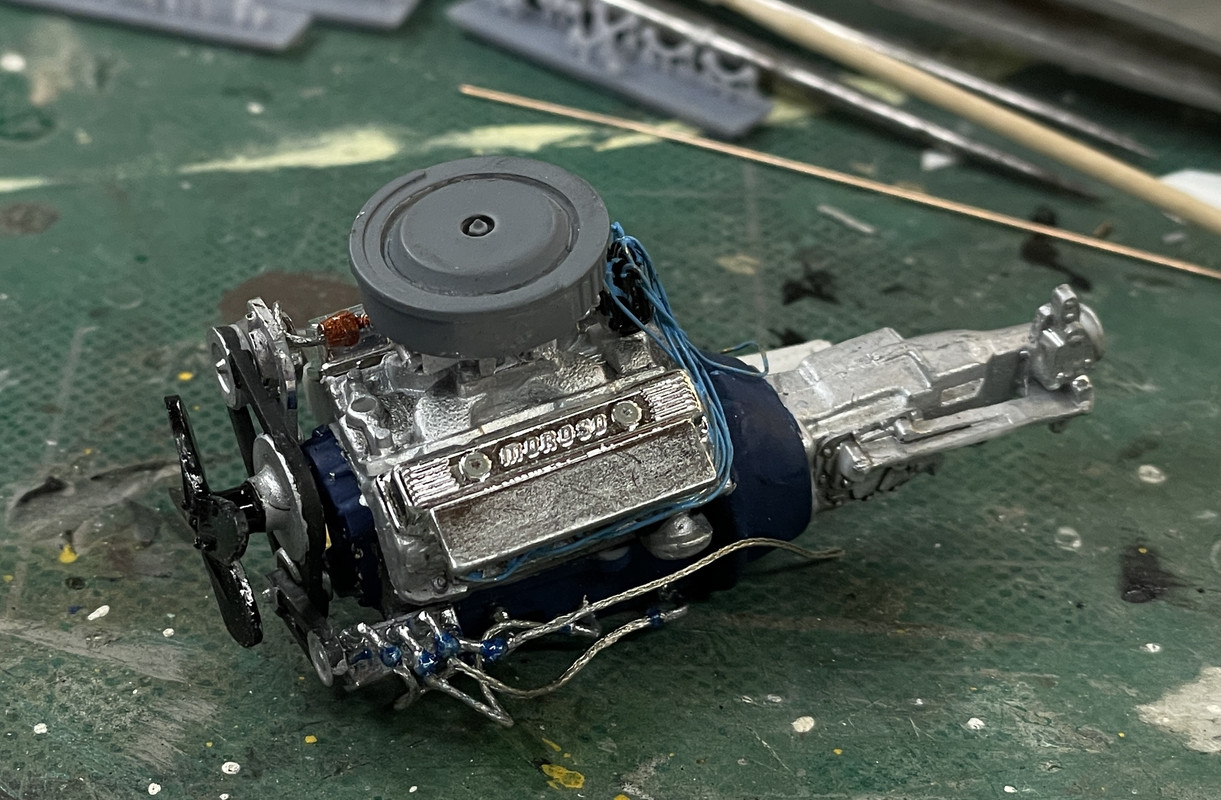
The braided lines are almost done. I’m not overjoyed! The coupling fittings I printed, while really scale, are too small to use effectively. I’m printing more today that are 30%, 33% and 36% larger to see if I can work with them better. I don’t think I’m going to redo the lines that are done, but I have more to do with the cooling lines and the oil lines to and from the oil filter and oil cooler. Regardless of how good something looks, if you can’t get the braided line into the fitting or the thing disintegrates when you try and open up the holes a bit wider while attempting to hold in a tweezers, they really don’t work at all.

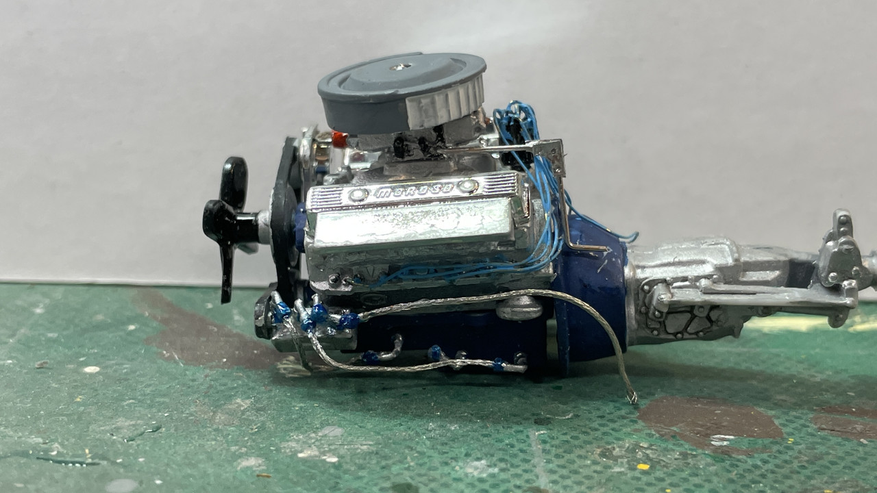
Here’s the fuel side with the line running from the fuel pump to the fuel rail next to the carb. The stock fuel pump is not prototypical for a NASCAR engine, but I didn’t have any good references to replace it. I designed the fuel rail fitting to be oversize so I wouldn’t have to wrestle with the braid insertion. While a bit big, it went together easily.

Closeups don’t do the model justice. Looks better to the eye…

The oil side works, but the line runs are too chaotic. With not being able to insert the braid INTO the fitting, only just butt-glued to the end, I really can’t manipulate them. As it is they kept popping off and are very, very unstable.

Another view with the air cleaner sitting in the final position. I have more work to do on the aircleaner. I drilled the oil filter for the in and out lines. I also don’t really know how the line goes in and out of the oil cooler.

At a distance, the engine will look busy, which afterall is the reason we put all this stuff there in the first place.

While manhandling the chassis to get the engine installed and drilling the hole in the firewall for the oil line to run to the oil tank in the car’s rear, I broke the upper roll cage cross-brace. This required pinning and gluing with CA to make it secure. It is not visible when the car body is in place since it’s up at the roof top.

3 Likes

FYI, There should be a braided line that goes from the oil filter boss on the rear of the block too the oil pump. You are doing a very fine job on this kit, Joel.

The new fittings work. They beefier and enabled me to drill them without falling apart. I printed them with the through hole, but it still needed some elargement. That said, they’re way oversized. They look like they’re better for a 1/16th scale model, not 1/24. But the scale sized fittings are simply too small to manipulate and get the braiding inserted. I’m going with bigger. It’s mostly hidden and adds interest.

It’s much sturdier than the previous versions I was messing with.

The piping continued breaking and I decided to replace them with the larger versions. In order to get this image, I installed the engine without both headers. I’ll get them in later. The piping just fit into the frame rails.

I also attempted to build a rundimetary throttle linkage that will go down along the firewall and disappear below. Again, not scale nore accurate, but busy. Air clearner is now on the model. 0.022" rod, while small in your fingers, is actually a little to robust. 0.012" guitar string would be better, but I didn’t feel like fussing with it.

2 Likes

Great stuff, love the added detail! Your persistence is definitely paying off.

Cheers, D

1 Like

Thanks!

Yessir! Persistence is my gift. I have very little patience and often (like today) rush paint and glue drying and have to do stuff over (and over). At my age, I’m still a pretty good model builder. As a kid, I was a terror. I’d crank them out like an assembly line.

Started decaling today. With the age of this kit… instruction sheet had yellowed… I picked one that didn’t matter too much about its integrity. As I expected, it started to fall apart. I then coated the rest of the sheet with clear gloss. If that doesn’t work, I have a fall back position. I scanned the sheet and will make my own decals should the coating not do the trick. Some of the decals have white details included in them. For those I will have to print on white-backed film and then razor cut around the perimeters so all the rest of the white paper is not included in the final decal.

This looked a bit rough, but after I put some micro-sol on it and it fully dried, it settled down pretty well. There are at least five tears in this decal.

With the decaling having to wait for another day, I got back to work on assembly. I gave up on using the oversized plumbing fittings on connecting the oil filter. There were too big to nest against one another and interfered with getting the engine in place.

I rehooked up the exhaust headers. It was a distinct pain to do it. They’re not set very tightly against their mounting surface, but nothing should disturb them.

I decided it was time to get the rest of the interior in. This included the funky shift lever, seat, blower behind the seat and the fire extinguisher. I had to do some internal surgery on the boot under the shift lever so it would center properly over the faux shift mechanism.

I moved rearward toward all the rear suspension parts. The first was this stub-frame that had very poor locating information. It calls for it to be painted blue. That surprised me since the rest of the chassis is black. I followed the instructions and painted it blue. This member basically supports the rear shock absorbers.

I got the remainder of the rear in. This was not easy either. I tended to rush the assembly and was doing things before the previously glued parts had set sufficiently. They broke loose a couple of times.

I sort of screwed up where the rear brake discs were going to connect to the rear axle. What were half-moon connectors I assumed were mismatched molds and mostly removed them. The discs are buried in the inner wheel hubs, so I may or may not include them depending on my luck installing them. I also found that I’d lost the metal axles. No proplem. Turns out it’s a convenient 1/16" and I had some mild steel rod of that diameter. Made it a little long and then measured the end play with the hubs attached, and trimmed to length. I have one of the more inexpensive Mirco-Mark mini-powered miter boxes. I have an abrasive cutoff wheel in the it and it makes quick work of cutting rods and tubing perfectly square and clean.

Pinned another one of the roll cage rod ends. The tiny plasitc pins and small glue area just weren’t holding up to the handling. Pinning with 0.022" rod does the trick and makes the joinery much more survivable to my rugged handling.

5 Likes

The project is coming along nicely, sorta surprised you didn’t replace the rear end springs.