Assembling Takoms M29 Weasel

I built one of the RPM Polish TK tankettes. @Tank_1812 Ryan’s photo is accurate - those are the tracks. My solution was to not cut the tracks out, but to cut all the sprues into individual pieces so that there was no pressure on the track part. Then trim off the sprue. Used Testors black bottle cement to glue them together, then wrapped them around the running gear to dry.

I’ve still got 8 more of these, different Marks, in the stash. Challenging little kits.

9 Likes

WOW Robin ! Your close up images are outstanding ! And the tips you share are hard earned !
I appreciate the detail Takom has given us but could they have made it a little easier?
Keep up your good work and I’ll keep making notes.
Thanks for you efforts and sharing them with us !

4 Likes

Yep, I do this all the time. Much better to cut into your nail than finger tip, and I have done that too!
Ken

2 Likes

I realised I needed to change my way of working with the #11 when rubbing my index fingertip over my thumb felt like rubbing the edge of a stack of paper.
Now I only use the blade when it is absolutely necessary. An additional benefit is that side cutters, files and sanding sticks give a better result.

4 Likes

Finally a little bit of progress, I managed to get the four corner bogies in place and aligned.
There is still some tweaking to do, one bogie lifts one axle a little bit.


The right axle of the bogie to the left is a little bit high.
It is difficult to check the alignment properly when posing the little critter on a flat surface.
The chassis doesn’t wiggle/rock but a rocker arm in a bogie could still be off.
I think it might be easier to see if it is positioned on a mirror, the gaps would be doubled
and more visible.

Some free advice: Do not handle small parts near a keyboard.
I almost lost one of the A24 parts (the little arms connecting the chassis side to the top of the bogie assembly). I tweezer launched it and it wiggled down under the keys, right between the two Swedish keys Å and Ä, I had to remove the big carriage return key to reach the AWOL part.


The lean to the left of the top edge is caused by the camera angle

16 Likes

Glad to see this post Robin - I was afraid it may have beaten you … :wink:

1 Like

Robin, thank you for bringing your build to us. Following with great interest, am I. :grinning:

1 Like

Agreed. Thank you for your continued build review of this model. As planned, Takom’s M20C Weasel just landed on my desk, destined for the Floats campaign. It looks beautiful in the box. The suspension elements are comparable to those found in a good 1/72 scale armor model.

2 Likes

um-hum,
that’s about how big it is …
:grin:

1 Like

nah,
not yet,
busy with work, X-mas, driving back and forth across Sweden,
painting those pin-head sized wheels will be a challenge though …

2 Likes

Your detailed build blog is very welcome! I’ve got one of the M29C kits in the que, and I’ve already bookmarked this thread for later reference.

Thanks for taking the time and effort to post it all up here for us!

Happy New Year!

5 Likes

I got distracted for a while so progress has been really slow.
I managed to get all the axles aligned, both sides aligned on the same flat surface.


Front and rear bogies in place, aligned the leaf springs between them.
I presumed that it would be easier to get everything straight if I could align the springs without worrying about the bogie and the “control arm”.

The other side with the center bogies in position.

I mentioned that taking photos on a reflective surface might be useful to verify that all axles are in line
so I tried that idea on a mirror filched from a broken overhead projector:
360_F_25982728_uwZ8XQE48FX0gHhOK6k1hmBh5eE9PqTA
The mirror has been hiding in a desk drawer the last 38 years and finally I had a use for it …

The styrene is soft and resilient enough to allow for some ‘tweaking by force’ which allowed me to adjust the positions slightly. Joints can be softened for tweaking by applying some ethyl acetate to the joint.

Edit: For those who haven’t gotten ‘up close and personal’ with one of those projectors:
Those mirrors have the reflective surface on the front of the glass instead of the back as a regular mirror.
This eliminates the distorsion caused when a projected image has to travel twice through the thickness of the glass. It also makes the reflective surface very prone to scratching …
In this case it has the huge advantage of not adding the thickness of the glass between the object and the reflection.

11 Likes

Continuing to follow. Thanks for the update!

IIRC, that’s the same sort of mirror that Shep Paine used in several of his dioramas to create the illusion of depth and distance. The reflective surface eliminated the visual “gap” that the thickness of the glass gives to regular mirrors when they’re placed right against something. He did an aircraft factory floor diorama with these types of mirrors on both sides to create the illusion of a long assembly line. The mirrors reflected the modeled scene as well as creating the “infinite” reflection effect of two mirrors placed facing each other.

2 Likes

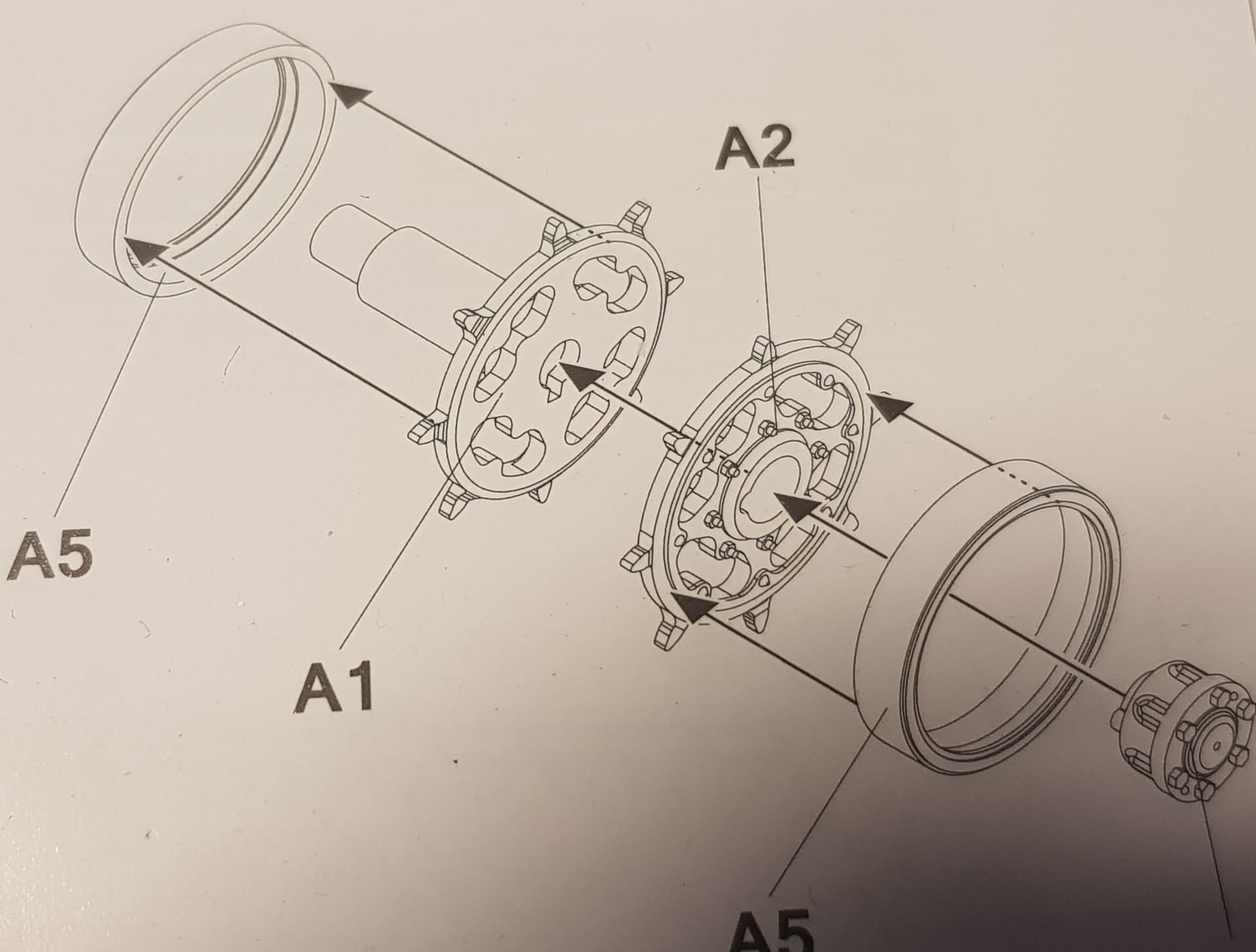
Assembled the sprockets, five fiddly parts in each.


NOTE that the A5-parts have a small lip on the inside, perfectly visible on the assembly diagram but rather hard to see in real life. This lip is the reason for molding these two as separate parts.
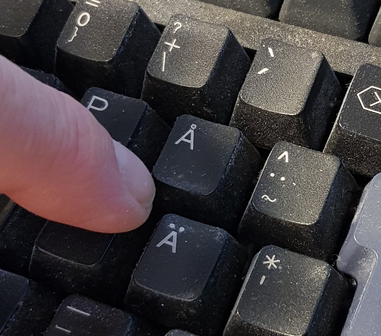
The little hub cap , A13, is small, one of mine tried to make a run for freedom but I caught the little bugger after sweeping the whole floor and sifting through the dust and particles (I really need to vacuum the floor)

Free advice: Do all the handling over some kind of tray, the bottom tray from a large model, such as Pz IV or Sherman would be just right. Those dang small parts WILL try to escape and a tray will prevent most of the escape attempts.

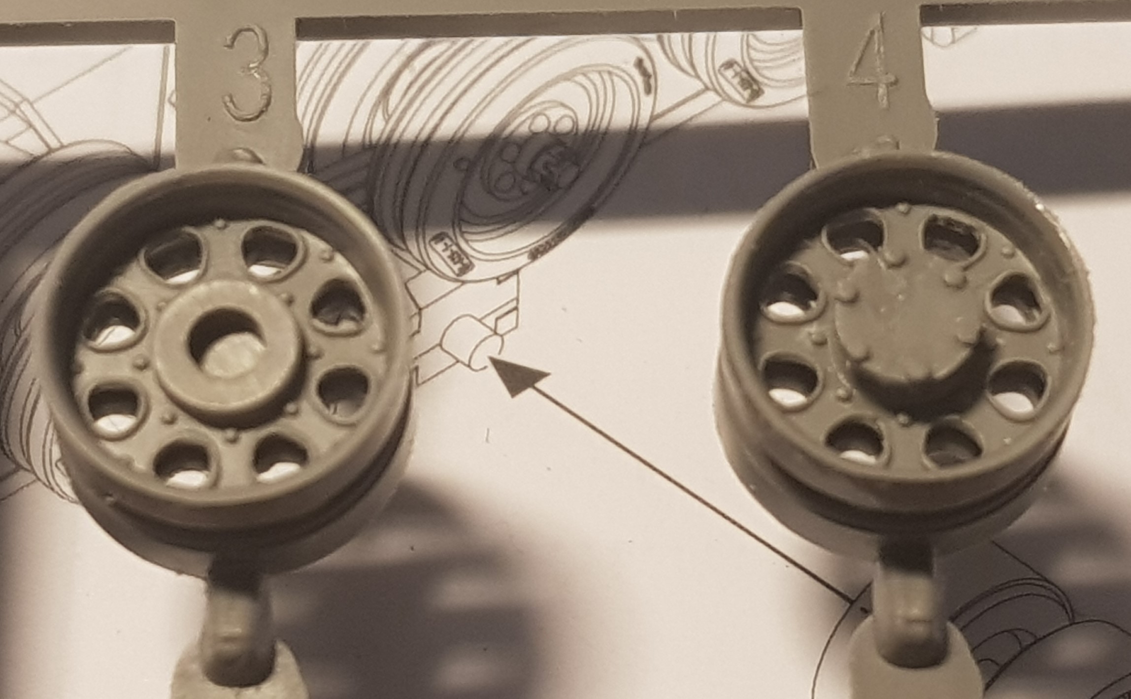
Next up were the two idlers, similar but NOT same hub cap, A12 in this case, don’t get them mixed up.

The idlers also get a small PE-ring. I haven’t glued it on, my CA went bad quite some time back …

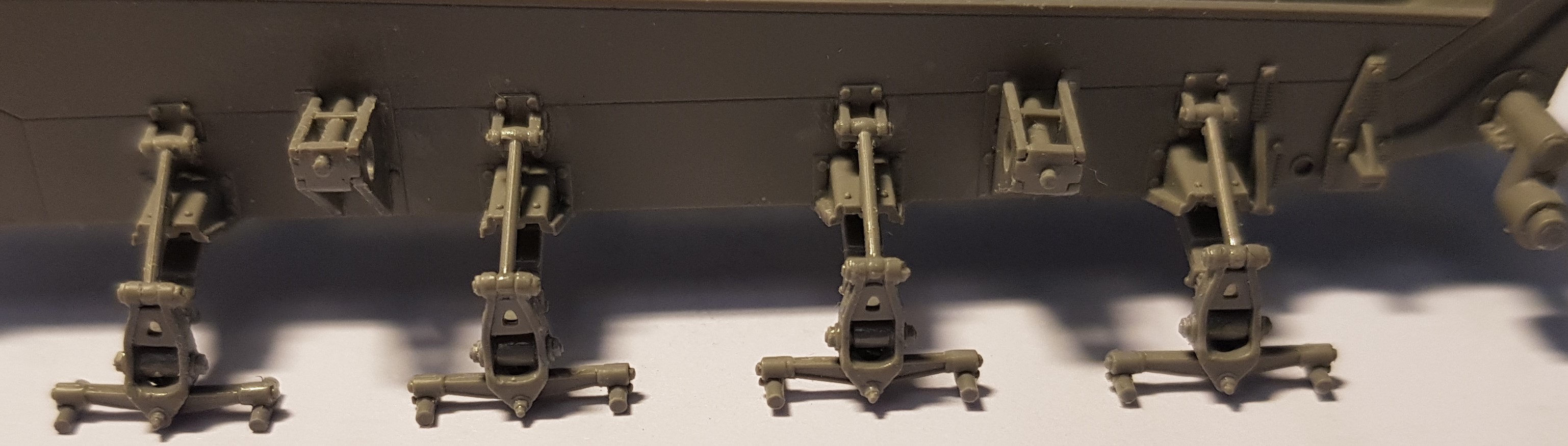
The completed assemblies. I included a return roller from Tamiyas M51, IDF HVSS Sherman, as size reference.


A3 is the outside half of the idler BUT in the photo I have glued A4 (the inside half) to A3.
This leads me to the second Free Advice: Glue the tiny parts to the small parts before removing the small parts from the sprues. This makes it easier to handle the small parts when trying to position the tiny ones.
I would have gone nuts otherwise …
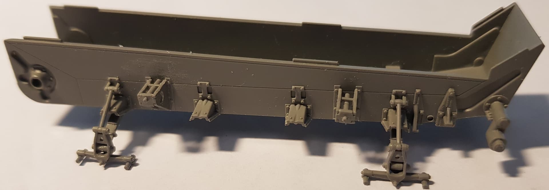
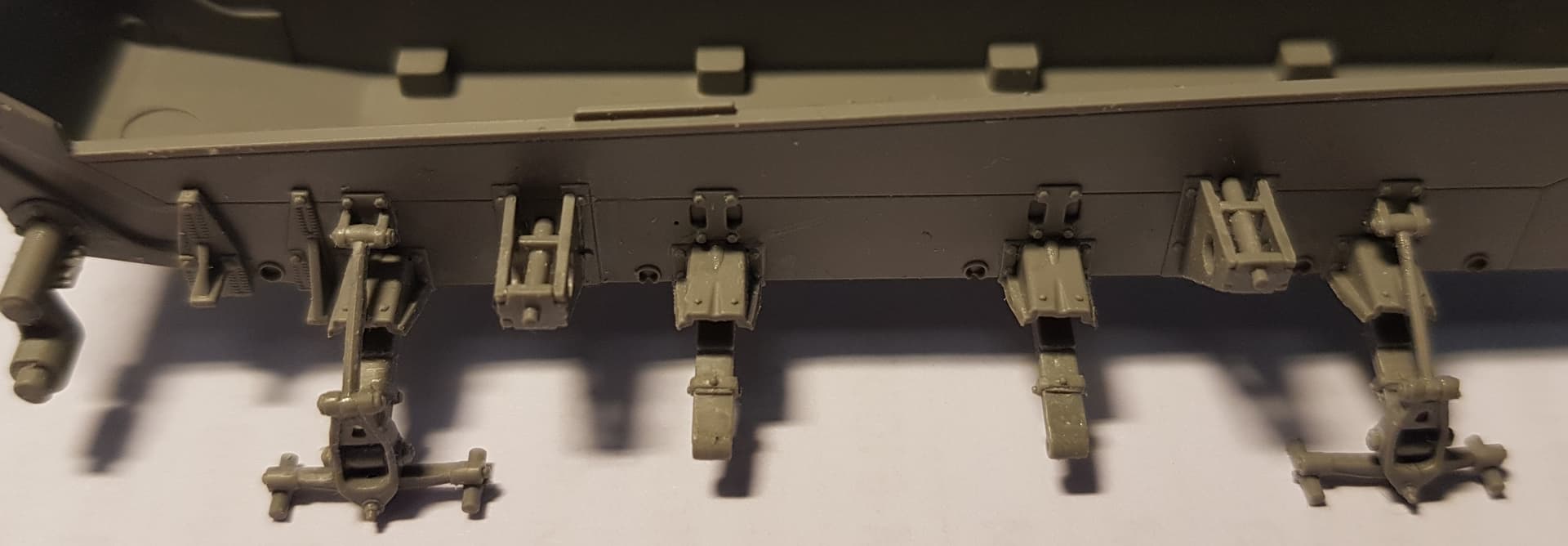
I glued the halves of the sprockets and idlers to each other on the sprues first, they are still there as the photos show. Don’t want to lose them …

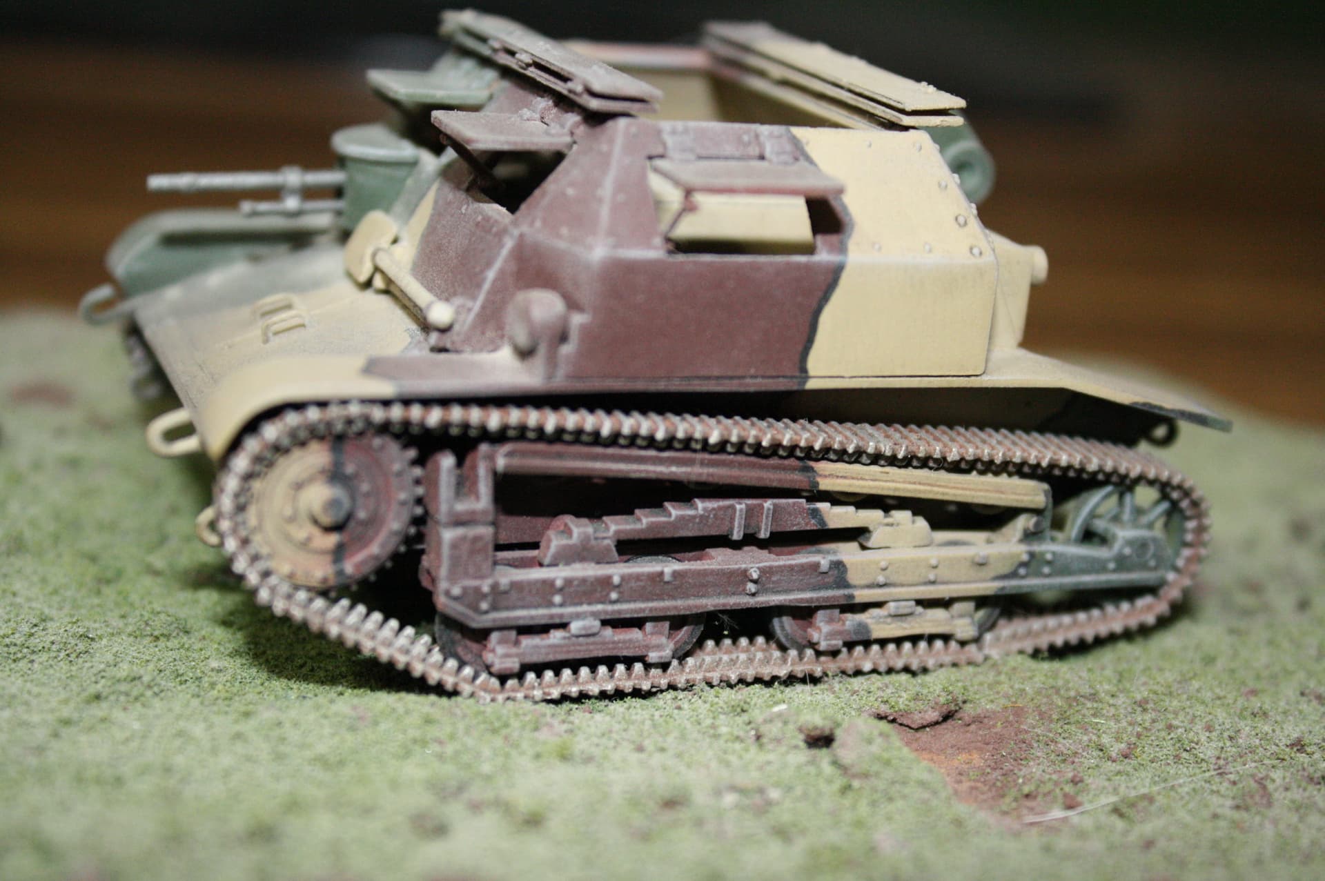
Note that the road wheels on the Weasel are quite a bit smaller than the sprockets and idlers.
The return rollers are barely slightly larger than the A12 and A13 hub caps.
That will be a lot of fun …

The fit is very good though, the hard part is to get the small parts close enough to each other so that they slot into position.

Oh, one last thing: the hub caps A12 and A13 are keyed to get the orientation correct. Lots of fun since they have to be aligned correctly before trying to get them in position or get them roughly right and then rotate slowly. … aaaarrggghhhh.

10 Likes

I wonder if this whole assembly of suspension parts could be simplifed using 3D?
Keep on trucking.

3 Likes

Those lips would most likely be possible in 3D.
I have too little (i.e. NONE) experience with 3D to be able to judge if the suspension could be simplified.
Just having the springs printed as one piece with the bottom of the hull would make alignment a lot easier.

3 Likes

Excellent build log thus far Robin, :+1: :slightly_smiling_face:. Looking forward to following this build as I would be tempted to get the ‘C’ variant, and I imagine much of this build would apply to that vehicle.

I recall, as a callow youth, seeing a Shep Paine build of the old Monogram kit wading through some rushes, or some such, and was suitably impressed and inspired, :slightly_smiling_face:.

G, :beer:

3 Likes

Nothing much to report on the assembly front. Sort of got stuck figuring out how to proceed with the little roadwheels. I had to spend some time on “research” (i.e. Googling for images) to find out how the real wheels are constructed. Many photos showed a difference between the inner and outer halves of the pairs.
An image says more than a thousand words.

  1. Rubber ring on the outer wheel half
  2. Painted side of rubber ring
  3. Narrow steel rim painted OD
  4. Inner wheel half looks as if it is all steel
  5. Space where the inner half does not touch the track.
  6. Width from inside the rim to outside the rubber
  7. Load carrying raised rib which the outer wheel half rolls on

My interpretation:
Two halves, the outer one has a rubber ring and carries the weight onto the track (rolling on nr 7),
the inner or center half is all steel and rubs against the guide teeth without carrying any weight down onto the track (void under, se nr 5)

The painted over rubber might actually save me since trying to paint such a narrow rim edge without making a mess on those tiny road wheels. The diameter of those little buggers is 5.6 mm (0.22 inch) so the width of the visible edge of that rim, nr 6 in the image above, is 0.65 mm (0.02 inch). The visible edge of the rim, nr 3, is approximately 0.11 mm (0.004 inch) and that is beyond my abilities when it comes to painting.

Overpainted rubber is the solution. I’ll paint it black first and then a thin layer of OD and try to get some extra OD on the edge of the rim.

8 Likes

Looking great.

Cheers,
Ralph

1 Like

Another small update.
The instructions, step 6, tells the builder to assemble parts C15, C16, E54, E31 & E16

In step 8 the radiator and the shroud gets inserted into the front part of the floor.

In step 10 the completed floor is added to the bottom of the chassis.

My usual approach is to assemble big parts before adding fragile parts.
This time I assembled the subassembly (except E4 and E31) before testing it against the floor.
I needed to test fit it to figure out the correct angle of part E31. E31 also seems to be slightly too long since it tried to push C15 and C16 outwards.
Luckily the solvent (“glue”) hadn’t evaporated yet, the radiator assembly is too wide to fit into the floor. Pull apart, clean up the softened plastic, fit the floor to the hull to make sure it fits correctly (it did/does). Fit C15 and C16 to the floor. Align carefully and leave over night to dry (that was yesterday).

Filed down the edges of E54 (radiator) and the mounting edges/tabs inside C15 and C16.
It was only a matter of 0.3 mm (a little over 1/100 of an inch). Plenty of dry fitting …
When it fit perfectly I glued it (solvent …) in place.
After the “adjustment” of the radiator width E31 will need to be shortened to fit correctly.

In step 6 it looks as if E31 passes through E31. It doesn’t. This is clearly seen in the diagrams for step 8 (see above).

The mesh pattern on the radiator is really nice, I don’t know what the real one should look like so maybe I am happily ignorant. It gets mostly hidden later.


The shroud sides seen from the rear. The left one, part C15, has an angled bottom corner which makes it look non vertical. Check alignment/verticality from the front instead.
20240313_001413

The fuzz is caused by filing, only visible with magnification. Already taken care of.

Radiator in position, seen from the rear. The deep groves are cuts I made to keep track of where the slots/tabs should align. I needed those since I had filed off most of the slots/tabs …


The horrible scratch marks at the top edge of the radiator are caused by a serrated tweezer.
The styrene is rather soft …

11 Likes