We’re still on the first page …
Those small fiddly bits are tricky …
There will be more notes later today, I promise, scouts honour and all that (even if I was never a boy scout, I got to play in the forest, use knives and axes and tie an occasional knot anyway)
4 Likes
I see now that the C version is out. I wonder if any changes were made to the kit to improve it?
2 Likes
My guess is not, as it appears to be existing sprues plus one extra.
2 Likes
I can understand why other model builders are having problems with this kit.
I spent an hour assembling 5 parts.
Do NOT follow the assembly instructions since that could lead to an extended “vacation” in a mental asylum.
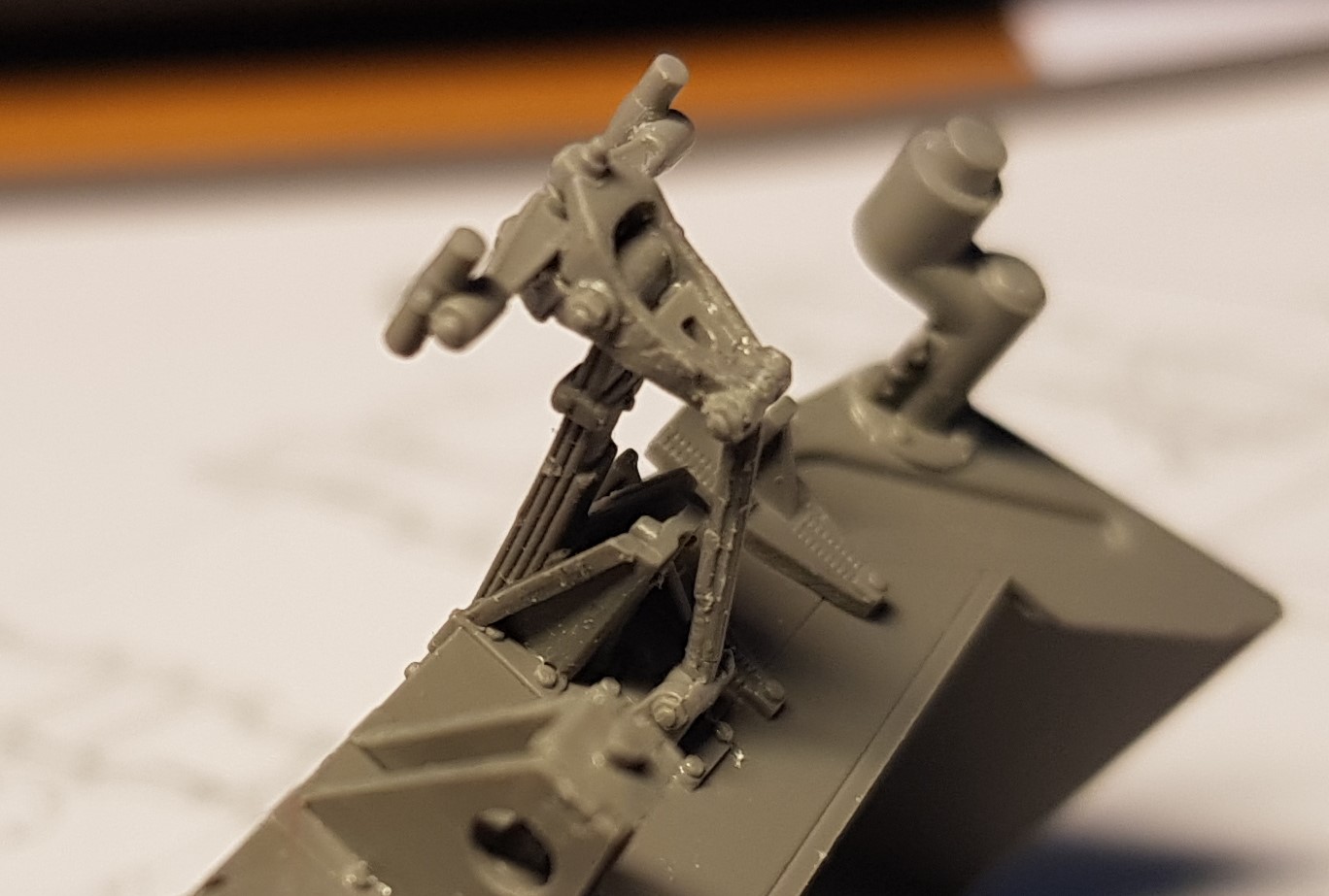
Step 1 tells us to glue parts A20 and A24 to the lower hull tub. These two parts are the spring and control arm for the bogie assembly. The distance between the outer ends of htese parts depend on the bogie assembly. The bogie is constructed in step 2. A misalignment of the parts in step 1 could therefore lead to fit problems in step 2 and to the model builder having a fit (see note above about mental asylum).

- There should be no gap between A20 and the hull tub
- Remove the mold line, I found a walkaround where the ends of these spring were visible. No such line/edge
- That little tab fits in a small slot on the back of part A19 (from step 2). Part A24 is FRAGILE, trust me …
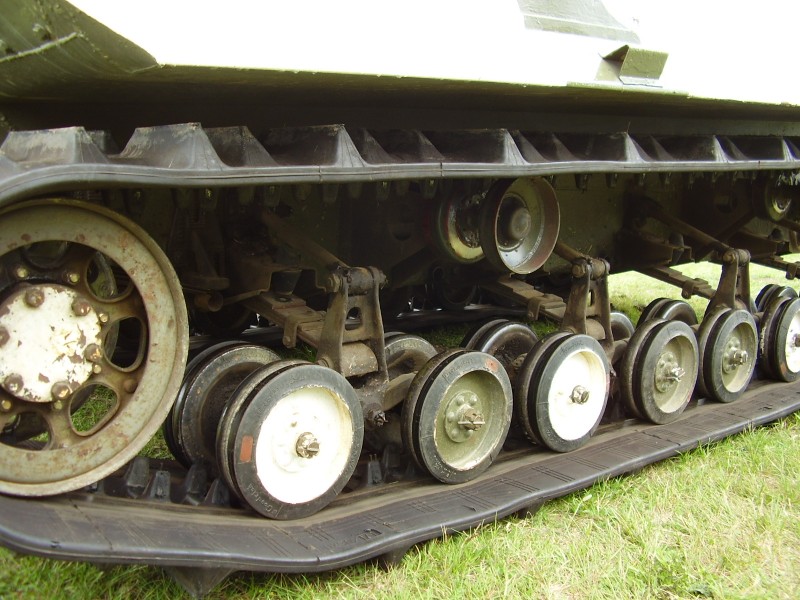
The wheel bogie fits between the tab and the spring. The spring is inserted in a hole in A21. On the real thing the bogie can pivot a little around the end of the spring, being held vertical by the control rod (A24). The joint between A20 and A21 could be made moveable (with a lot of bad words polluting the air). Since A24 can’t move there is absolutely no point in making the bogie moveable.
Here comes the dangerous part:
The instructions tells us to glue four pairs of wheels to A23 (rocker arm?) BEFORE assembling A21 - A23 - A19. Getting A19 and A21 properly located in between the wheels seems like a very difficult operation.
Getting the bogie assembly located between A24 & A20 will be more complicated with the wheels attached.

6. Do not glue the wheels. Assemble A19, A21 and A23 first. Worry about the wheels later.
4. A23 has small tabs by the pivot point, the tab that fits A21 is the smaller one. The tab is keyed so the rocker arm does not rock. Glue A21 to A23, let the joint harden.
5. The larger very small tab fits A19, glue A19 to A21+A23. Let the joint harden
7. The control arm, A24, fits into this slot. The tab on A24 fits into a slot on the rear of A21.
8. The spring, A20, fits/clicks into this hole. Never mind the click fit, it will not be movable anyway.
Glue the bogie assembly to A24 and A20, wait a little so that the joints are still soft but not loose and then glue the whole assembly to the hull tub. There shouldn’t be any gap between the spring and the hull tub.
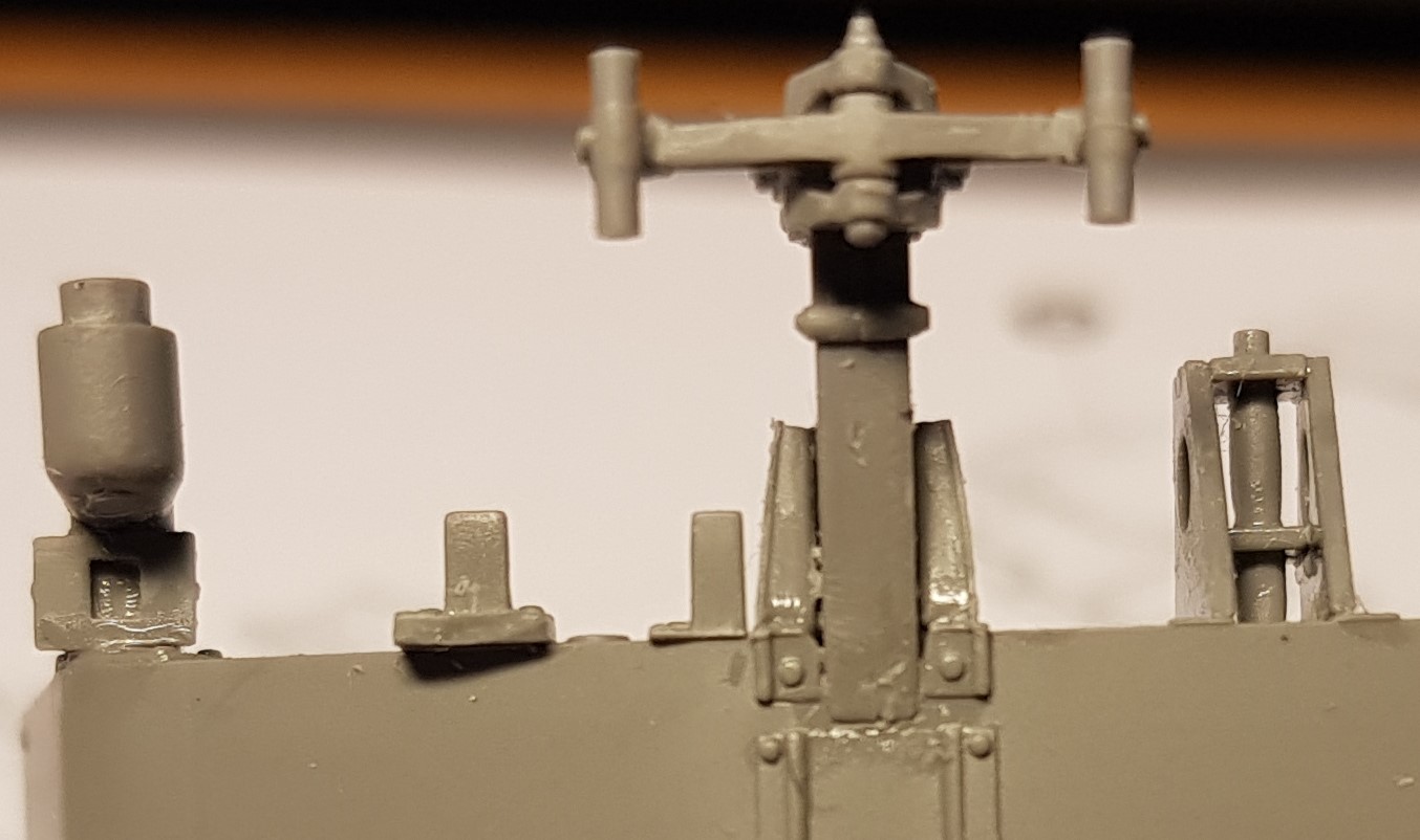
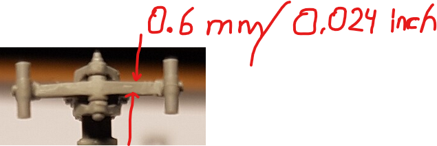
The parts are very small, the rocker arm is 10.3 mm long, wheel diameter is 5.6 mm, 8.7 mm axle distance in the bogie. This leaves a 3.1 mm (0.122 inch) gap for parts A19 and A21. Doing that assembly would require two tweezers and the third hand handling the glue.
My way forward will be to clean upp the remaining 7 instances of parts A21 and A23 and glue them together. When those have hardened add A19, let harden. Add A24 and A20 and glue to the hull tub before the glue sets too hard. I will start with two bogies (left and right) at one end and make sure the hull tube is level side-to-side. Let harden. Add two bogies at the other end and adjust the front-rear angle while maintaining the side angle. Let harden. Fill in with the remaining four while making sure they touch the “ground”.
The real thing seems to lift the first/last roadwheels
Image in Armorama feature
The rocker arms are all the same part, the lower track run is a solid length and I doubt that it will allow “lifting” these road wheels.
10 Likes
What @Tank_1812 says …
3 Likes
Almost forgot the photos:
Some cleanup will be needed …

Partial fingerprint of left index finger on yours truly.
The mess is barely visible without good glasses or magnifiers. To be cleaned up later.
13 Likes
Nice build. Keep up the good work.
Cheers,
Ralph
1 Like
Looks like a few mold issues in these last few pics. Is the rest of it so roughly cast? Nothing worse than trying to clean tiny parts with massive seamlines all over.
Ruck On.
1 Like
Very minor seamlines.
Moulding is top quality, I have seen better but I would say that it is in the top third at least.
The HUGE injection gates on the photos are actually on the small side but the parts are even smaller …
3/128 of an inch
4 Likes
Managed to clean up and glue 3 pairs of parts A21 and A23.
The next step is to glue 3 x A19 from the other side
Still some minor clean-up to do, zooming in on digital photos reveals very small blemishes.

3 x part A23 chilling on a nr 11 blade

The small pencil circle is nearly dime sized (17.9 mm)
The “sword” in the upper edge of the phot is a small needle file.
I trust that you all recognise a nr 11 blade.
The section of sprue holds 3 x part A19 which need to be fitted to the back side
of the parts in the circle. All snipping from sprues done with the huge jaws on the left.
The driver also lent a hand (whole arm) to get yet another size comparison for those who
don’t have a dime handy
Careful is the word of the day …
Maybe I should show these parts fresh off the sprue?
Show the mould quality before I go wild with the file.
10 Likes
Impressive!
Along for the ride.
2 Likes
Damn, I would have given up by now ![]()
3 Likes
I plan on building one of these, but damn, that’s bat-sh!t crazy when the part is the same size as the sprue gate!
4 Likes
So think of it as an Eastern European manufacturer before 2000’s and proceed accordingly with the build.
4 Likes
Consider building over a large empty box to improve the chances of retrieving parts that try to escape. Bottom tray of the box for a Leopard 2, Abrams or similar largish kit.
They will try, trust me on this …
Last nights antics took place above my keyboard where tiny parts can disappear between the keys leading to disassembly of the whole keyboard. Maybe I should follow my own advice …
I save one sprue attachment point for as long as possible to give me a “handle” on the small parts.
Let the nail on your thumb grow. Cutting towards you with the nr 11 gives the best muscle control over the blade BUT it places fingertips in harms way. Clamping the part down between thumbnail and tip of index finger lets you use the nail as “cutting mat” while removing the last bits of the gates, one paper thin sliver at the time.
Some injection gates are between surface detail and
if your smallest file is too large you will be in trouble …
Holding the tiny part between thumbnail and fingertip allows more control during clean-up than with tweezers (remember: tweezer launch …), especially for rounded parts (such as A19 in this case).
6 Likes
I still need to work up the courage for the indy-link tracks of the Polish TKS tankettes made by RPM. Brittle plastic, big injection gates, tiny track links.
![]()
![]()
Edit: Can’t find images showing the indy-links, I think they have changed the design of the kit. The ones I have in the stash are from before 1996
3 Likes

Looks familiar,
haven’t looked inside those boxes since back in 1996.
Could have been some other east-European kit as well.
Maybe it was the Renault UE by Mirage
Sprue photo
2 Likes
Looks like they are taking a page out of miniarts playbook…coming along nicely though
1 Like
one sloooooww step at the time …
![]()
3 Likes