Other option is to put up a ‘wanted to buy’ post and see if anyone will part with a set, or even the ones in the Academy 13202 kit at a pinch - BUT I can’t say I have much respect for Academy decals…:
I’m now on my forth prototype. My stash of styrene is either too thin or too thick. I’ve laminated the thin stuff. That’s ok. I then found the glue warped the layers. I got that figured out and made another prototype only to find I cocked up the length. So it’s currently sitting in the naughty corner. Tomorrow maybe!!
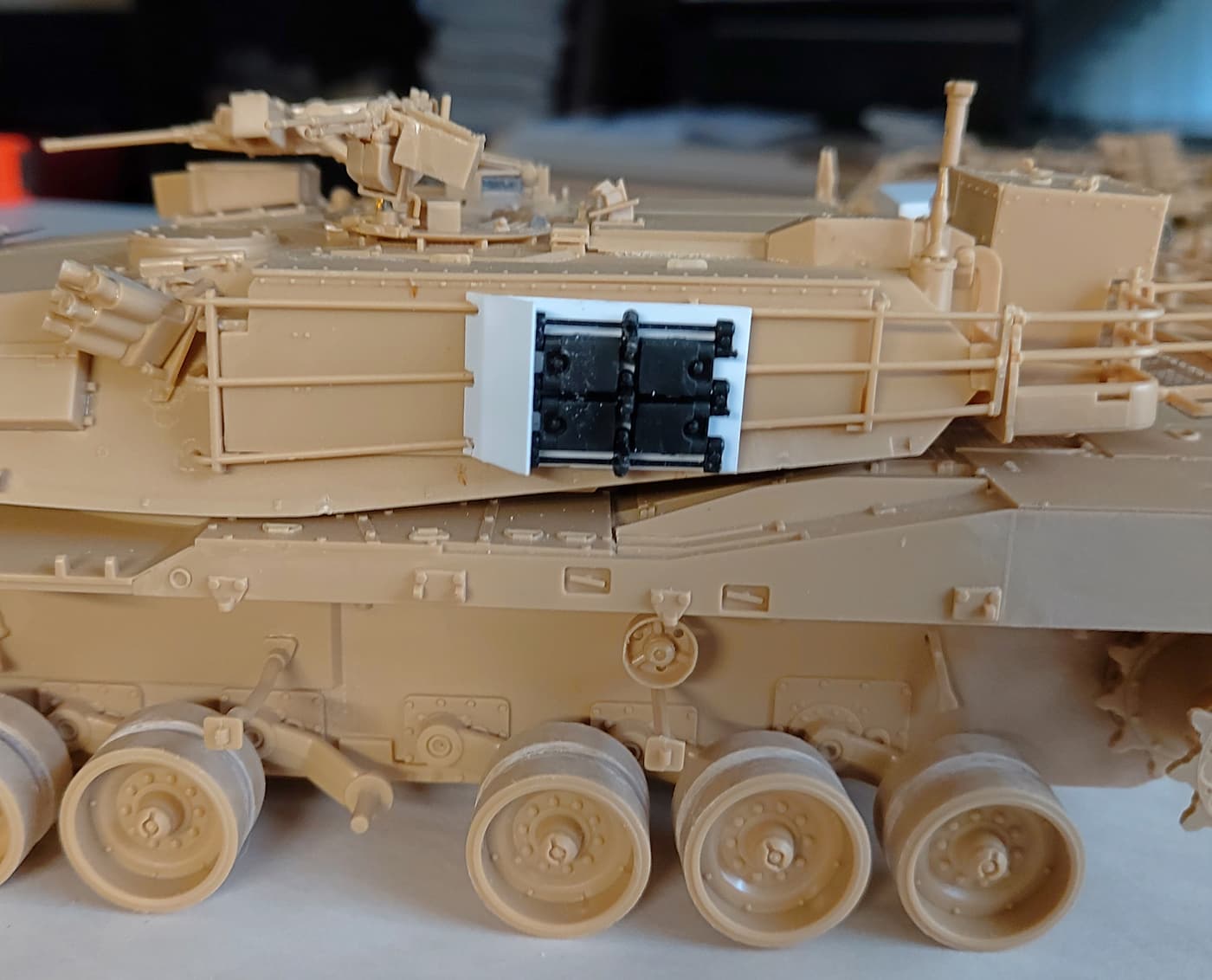
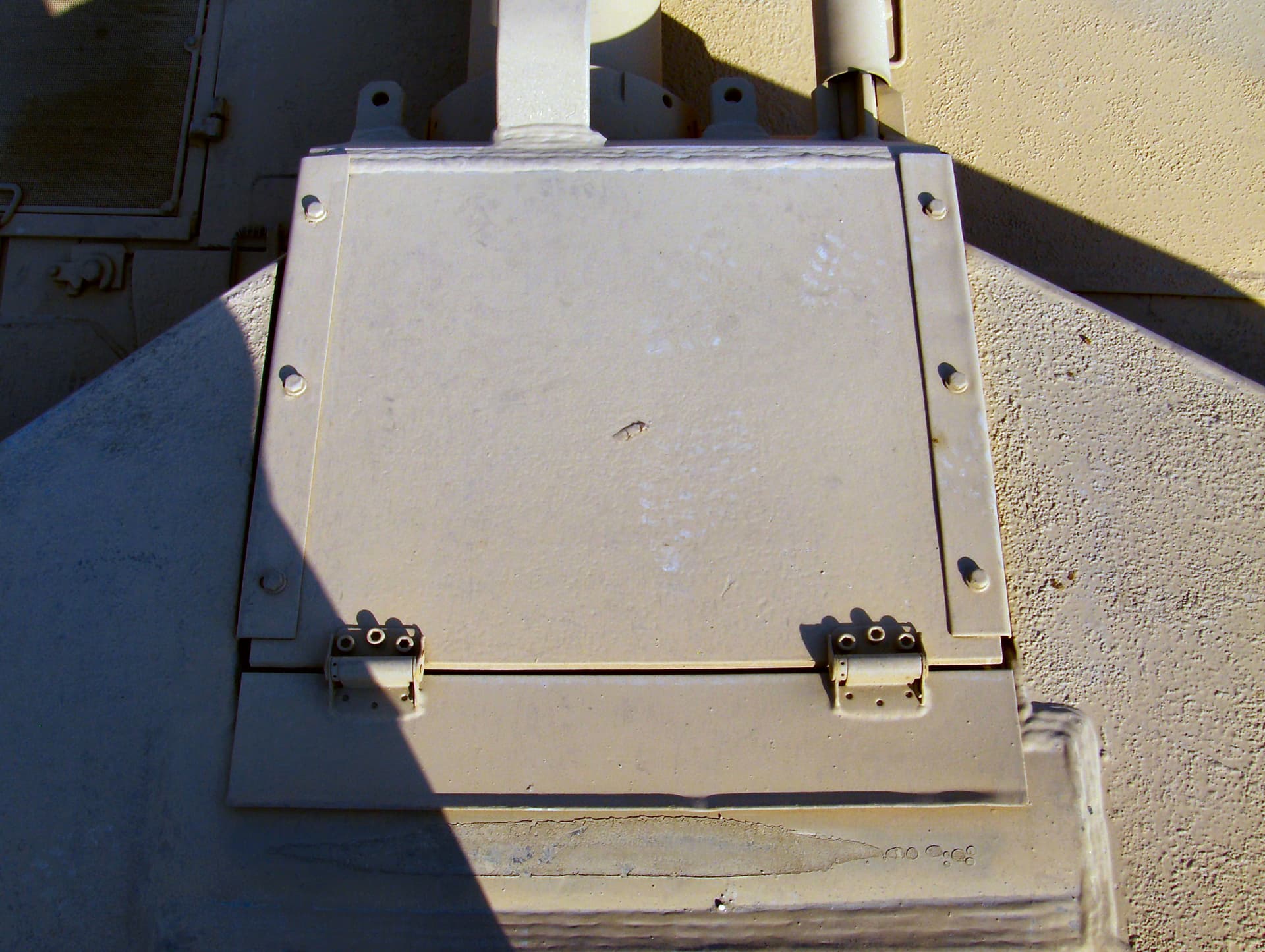
OK a new mockup. This time I think I have the location and proportion right. I have no images straight on so some of the size and locations are a bit sketchy.
Anyway I now think it’s about near enough. So onto some of the detail of how everything is mounted.
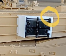
I like what you have done but I think the plate is too big long and not aligned correctly.
If you look at the top right red circle, the track is aligned with the existing iron post and the plate does not existed past the track. At that is how I see it.
Yes it does look a bit long. But there still needs to be the mounting fittings to the right of the track. There also needs to room for the gussets under the front guard.
OK some head scratching. Something I should have checked first.
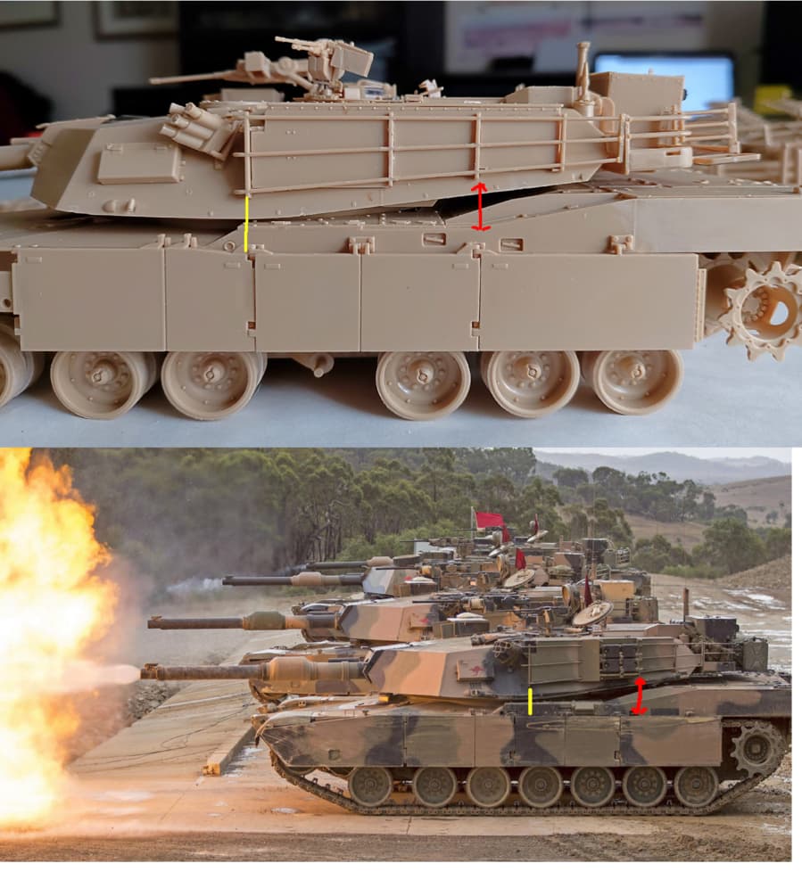
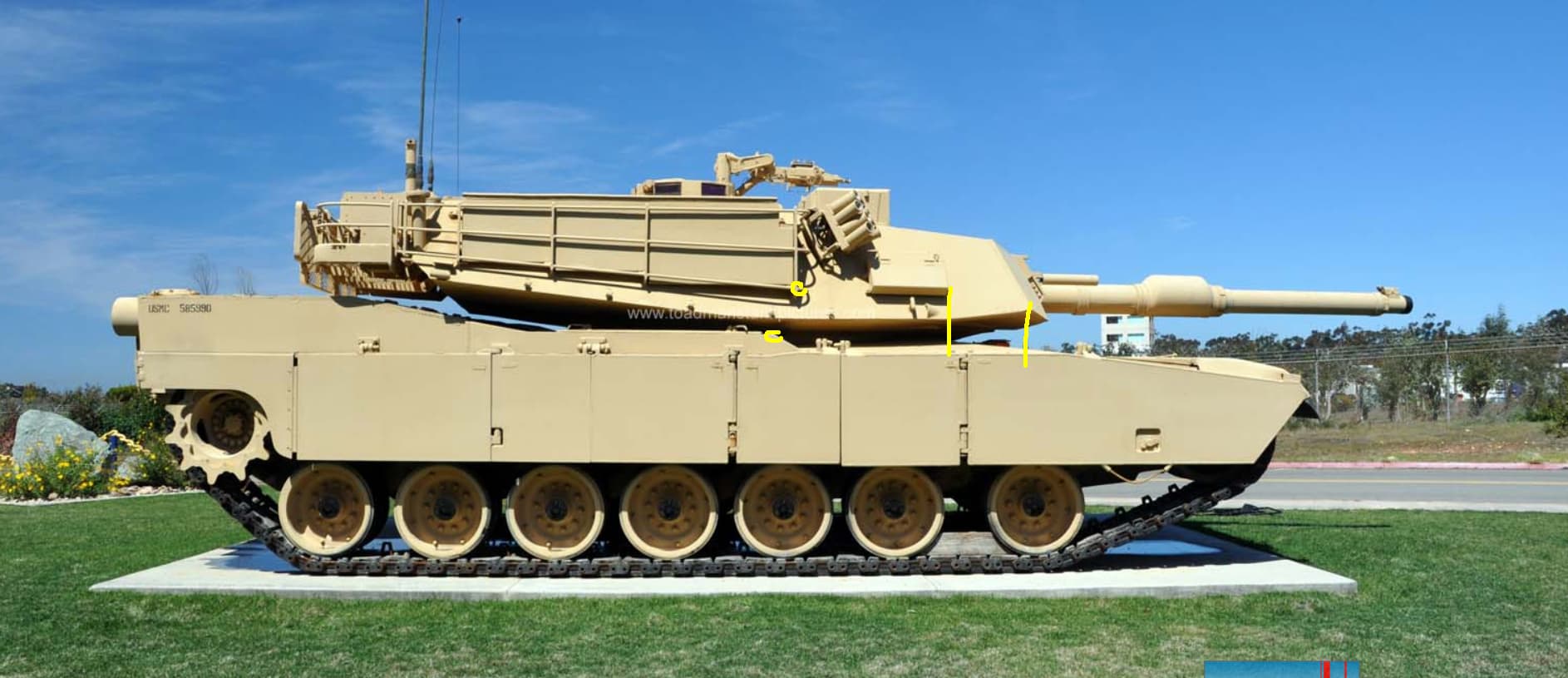
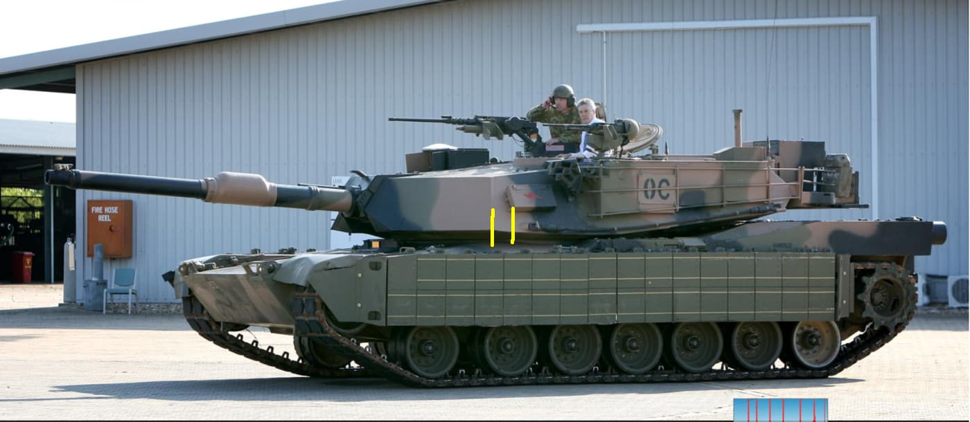
Note the below image. The red and yellow lines. Note how the kit side skirts line up with the framing on the side of the turret. Me thinks something is wrong. My attempts were based on the kit being correct. The red line on the kit lines up with the panel join on the side skirt. But the real thing is further back. The yellow line also lines up in a different place. My money is on the real thing being correct!
Maybe a question for Meng to answer.
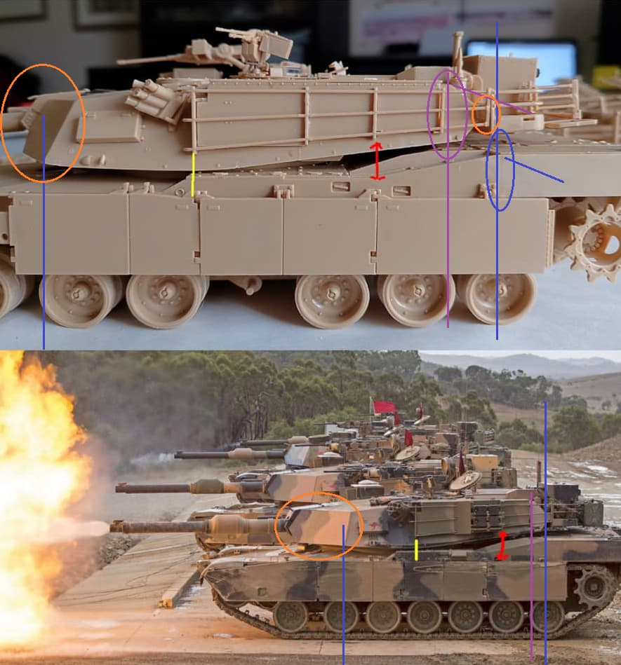
The one near the front is much narrower than the pic. Consider the position of the Vertical blue line near this section. The kit has the front to side join well before the second road wheel hub, but the photo of the Real Deal (RD) shows it in line with the rear of the hub.
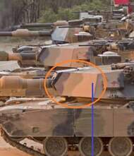
Go to the rear of the turret. The orange circle shows a gap between the rear ‘truncated triangle’ shape on the hull rear when compared to the vertical blue line rising from the rear road wheel hub, whereas there is no gap here on the RD. The purple line is the base of the triangular shape and it is in line with the 2nd last road wheel rim on the kit, but the same line from the triangle base is on the rim of the last wheel on RD.
Lastly, back at the front. Pink line shows the side plate join in realtion to road wheel … and space in front of the turret. Same position on the side plate may be okay to the road wheel on the kit after adjusting perspective, but that whole section of turret not so much.
Looks less like the turret is too far forward and more like the turret is too short!
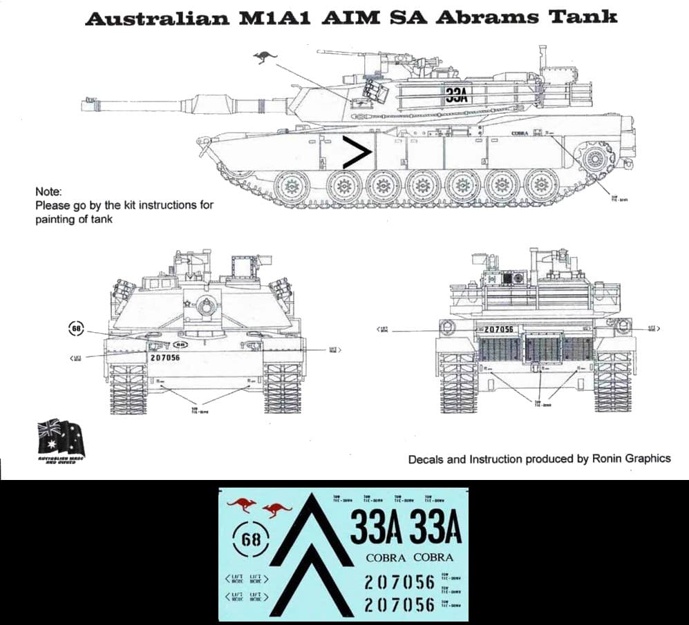
Thanks petbat. How do we find out if the Australian m1a1’s were different?
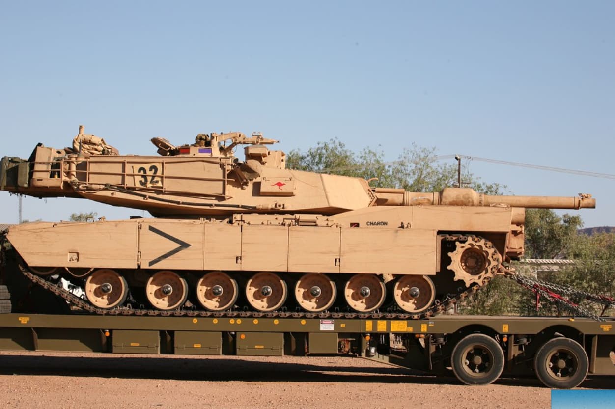
Here’s another comparison. Yes the angle of the photograph is different. But look at how far it is from the box with the red roo on it to the front plate when compared to the first image.
The Australian version clearly has a much sharper angled front to the turret.
So without the correct turret any attempt to use this kit wont result in an Australian m1a1.
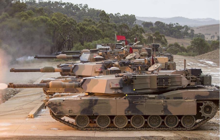
All very interesting. To me it appears the Aussie tank firing has its turret turned slightly and not inline which I admit seems strange on the firing line.
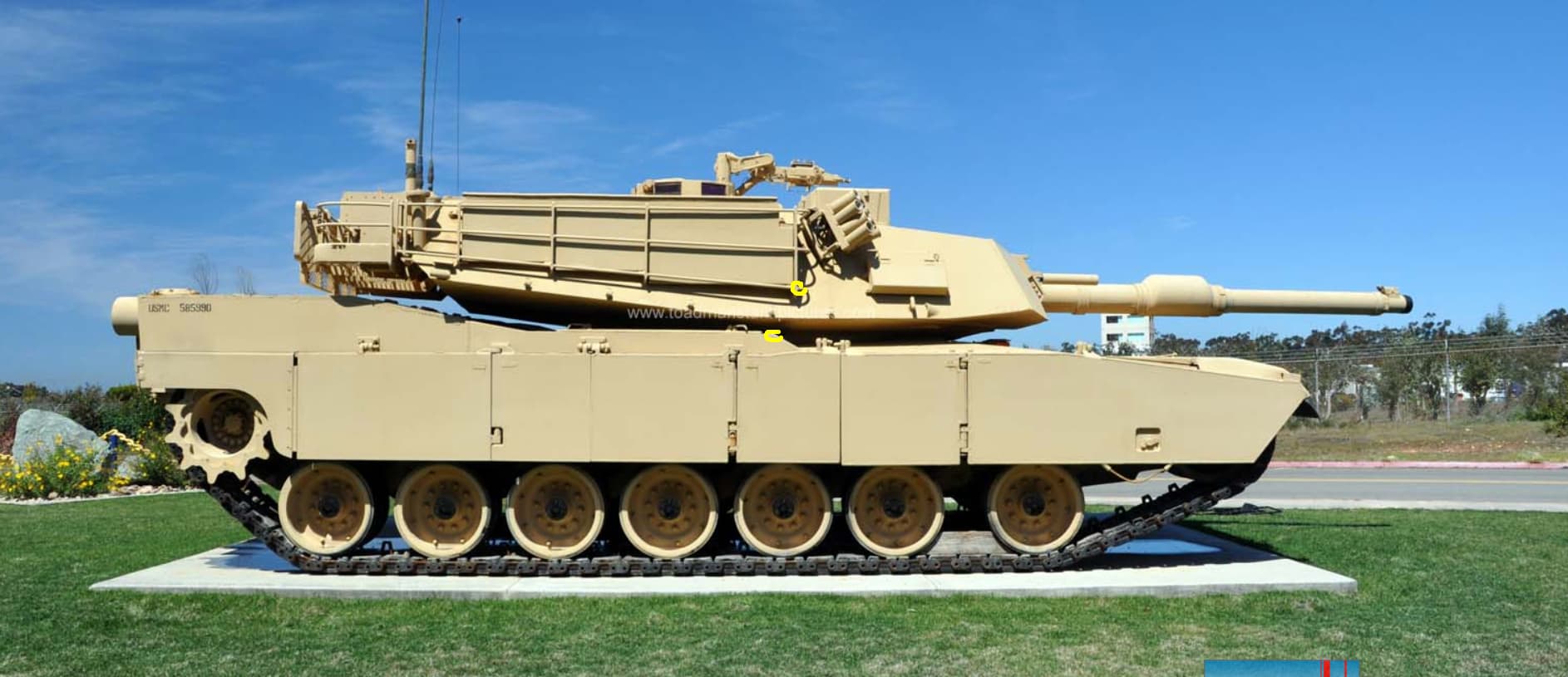
The US comparison tank is a Marine tank and they have a different smoke grenade launcher system and I wonder if that accounts for some difference on the box spacing. Along with the fact it’s a gate guard which means it’s probably an older A1 model. I wonder if comparing to Reserve/National Guard A1 (think the Army might still have some) or a more “active” Marine tank might not be a better comparison to match with an Aussie tank.
Check the fronts of the three turrets,
I get the impression that the two nearest have aimed their barrels to the left (drivers left)
while the furthest one has the barrel straight forward.
I completely agree that the turret on the nearest vehicle is turned and not aligned with the hull sides this would make any measurements or comparisons incorrect.
The gun barrel itself is centered to the chassis and turret ring. Perchance you might be asking that the turret itself is asymmetrical? Because it is. Looking at the vehicle from the top, with the gun barrel pointing up, the Left side is slightly smaller that the Right one.
I’m modeling one from scratch. Withouth getting too much into boring details, I’m eyeballing it all through a technical standard three views drawing (Front, Side, Top) I got from the internet. The picture below is a screenshot from the top view in my CAD program and is as accurate as the drawings I got to model my Abrams. Blue lines added as highlight.
The Blue vertical line is centered to the Chassis of the vehicle. See how the gun barrel’s center line aligns with it? Of it was off centered, the recoil would yank it to one side. That throws off your aim and is bad for the turret driving gear.
Horizontal blue line crosses the vertical one where the turret ring center is.
The reason for this is simple. The Left side houses the Loader. The Right side houses the Gunner and Commander. So, it’s two people with not a lot of arm room on one side vs one guy who needs room to safely load the gun manually with a 20kg+ round The problem arises when you have to wrap armor around them. And armor is very heavy, so the design team doesn’t add more than they judge necessary. Making the turret symetrical would give the Loader more room, but you’ll have to add more armor to cover the extra volume. It makes the turret bigger (meaning, a bigger target) and the vehicle heavier for no added benefit except more storage space.
If the weight of the turret is centered, that I don’t know. I believe it is, because having it offset would mean more wear on one side of the vehicle and that’s generally very undesirable as it means something will have to be replaced sooner instead the longest service life possible, to the extent that material and maintenance quality goes, if the wear is distributed.
Dfox touched on it a bit, all off the elements you are comparing (road wheels, side skirts, and turret edges) are all on different vertical planes so perspective comes into play . If the photo is even slightly off from a straight on view you will end up with distortion, the more so the further those vertical planes are separated from one another. Think of it as sighting through iron sights down the barrel of a rifle, the further the front & rear posts are from one another the more that will appear deflected at a given angle. The turret edge you are referencing will appear more vertical with the turret even slightly to the left.
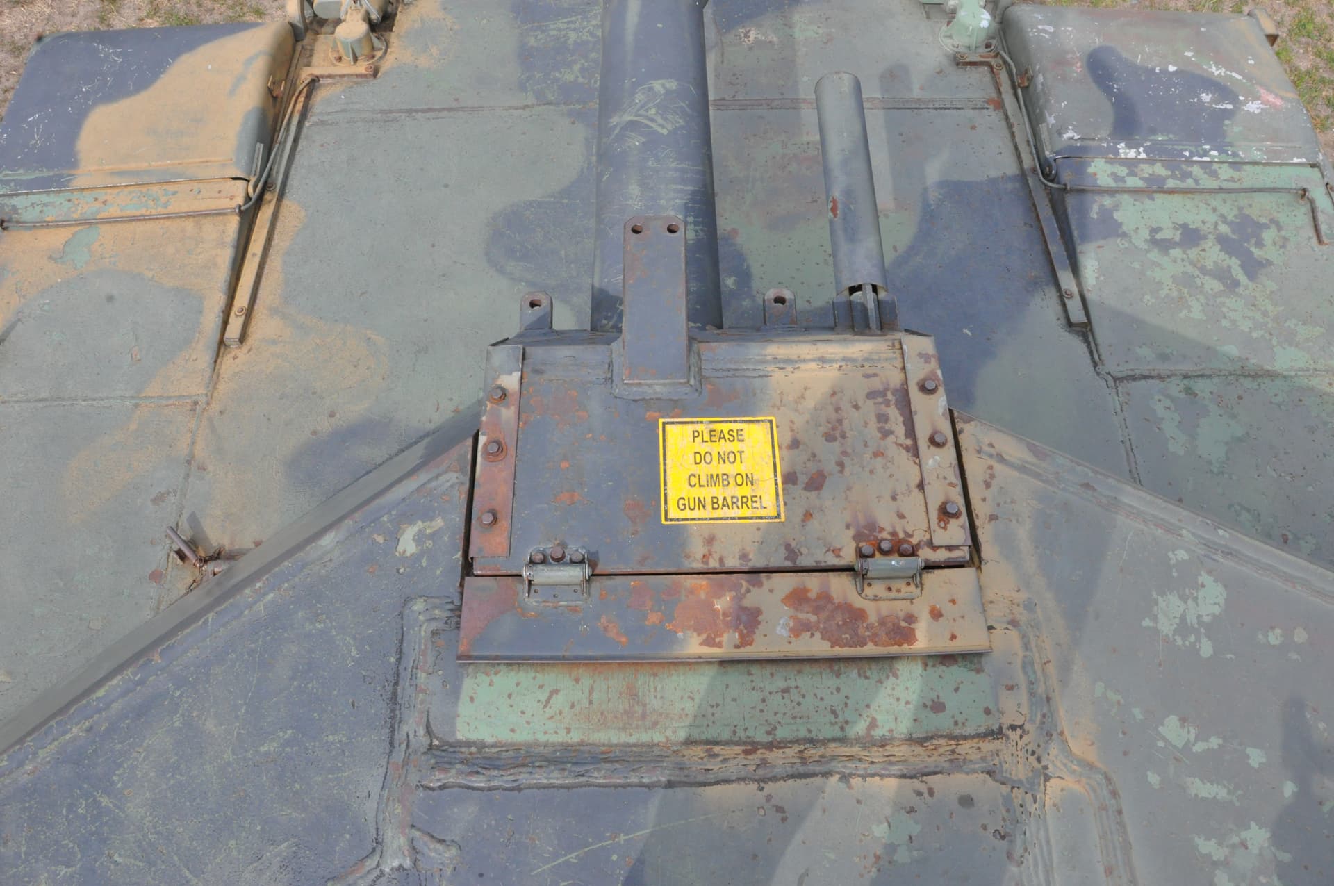
One more thing to note is that the over head drawing from the Quora article along with the drawings in Hunnicut’s book are incorrect with the placement of the mantlet. On the A1 the length of it increased along with the thickness of the turret face armor, the drawings show it the same length as on the base M1, in effect showing the trunnions shifted forward.
A professional engineer could probably explain it more clearly but this is what I’ve gathered in my own attempts to decipher photos, it’s a tricky business and may give some insight on what kit manufacturers go through to design a model.
EDIT
These were the photos I wanted to add at the time but couldn’t find them,
M1 mantlet
I agree the turret is definitely slewed slightly to the left. Do US tanks on a static range always fire head on, gun front over the driver ? When we were on some ranges (most)(Chieftain and Chally 1) firing static we would at times have the wagon at a slight angle and the gun slewed over to the left. Also, they may be tracing a mover and firing, or if not firing, ghosting, watching the other wagons engage - so there will be some movement of the turret.
Wouldn’t it put a lot of stress on the driver to line up the tank perfectly with the target?
I thought that was why the turrets could traverse?
The Swedish S-tank (Strv 103) had the gun fixed in the hull and the gunner/driver
or commander/gunner/driver aimed the whole tank …
I dislike the word always, but as I recall it was straight on. To be fair my world was confined to the world within the 3” reticle. I didn’t usually play attention to the vehicle orientation. As I recall it was not easy to know outside straight on when you might see the driver under the equipment. That got us in trouble once.