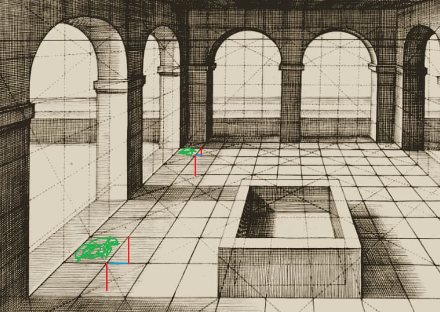
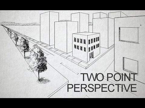
In a one Vanishing point perspective (viewing an object 90 degrees to its plane directly in front), the further you are from an object there is less impact of perspective on the vertical plane shift due to horizontal displacement, as the view direction travels to the focal point or vanishing point - i.e. there is far less impact over distance. Consider the length of the tile in this image and the horizontal dimension change for a front tile to rear (blue line).
I’m procrastinating at the moment. I have 2 issues. The correct size and location of the spare track plus the inability to find the decals.
I’ll chip away at the spare track and worry about the decals later. “Beer”? Well we will see. It may be Beer or its close cousin.
Your build has gotten me interested in the Australian’s abrams but decals are also giving me trouble. I’m looking forward to seeing the rest of the build though!
I’m glad I have ‘inspired’ you to look at the Australian m1a1’s.
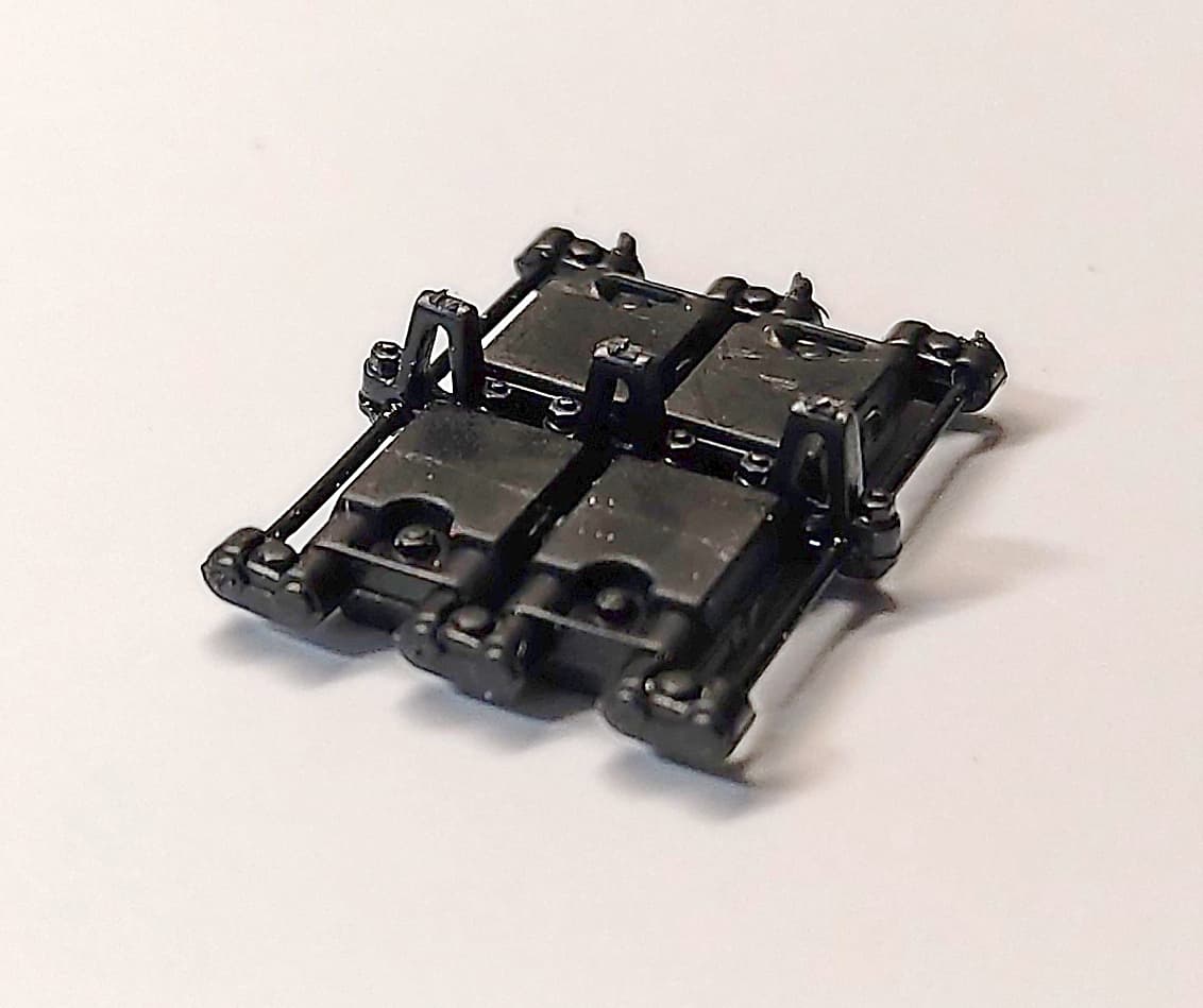
Enough of the prognosticating. I’ve decided that near enough is good enough. As long as it ‘looks right’. This morning I built the other side plates. Now I will tackle the detail bits!! Yikes that may be easier said than done. I’ve figured the front edge location and I’m working back from there.
Just a comment about ‘perspective’. It’s something that can easily trip up anyone in many number of ways. Usually the eye can pick it up but not always the brain. In years past I did a lot of semi pro photography and art work where I played with perspective. Here’s an example.
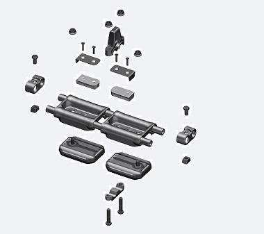
Then trim off the unwanted bits. Note I’m lazy and I’m using the lower track pin/rod to represent the lower thicker rod used to mount the tracks. Note one horn has gone as well as the top pin/rod.
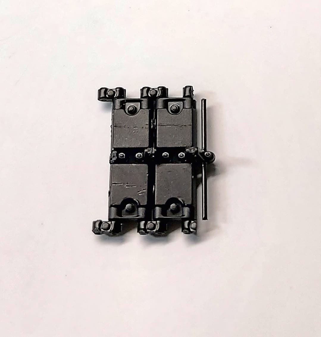
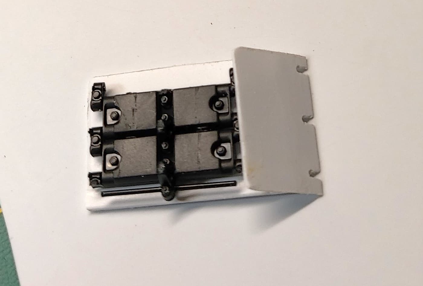
Here’s a dry fit. I need to build the vertical brackets for the lower rod. The top mount has me scratching my head. I can’t see from my image exactly how it has been done.
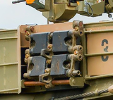
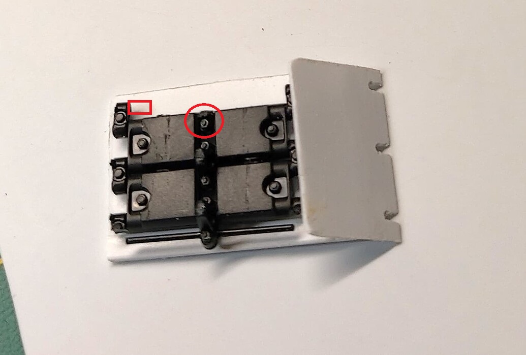
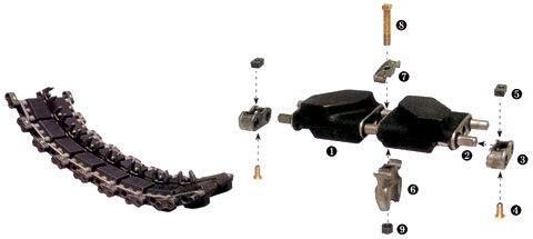
I agree w/Ryan, the top looks to have a bar on each side that comes on the inside of the end connector, with a small piece of rod that the connector attaches to. Red rectangle below.
Also, the part in the red circle with bolt left over from the center guide should not be there. It should all be removed and just a smooth rod there. Reference the track pad below as well.
The problem with removing material from the red circle is that once I removed the horn there is very little material left. It’s all one peice so in affect I would have to create the track pin. I will see how much I can remove without saying “bugger”.
The Meng kit has some spare tracks but not enough to keep destroying them.
In hindsight if I was to start over I would use copper sheet as a basis rather than styrene. Just better to work with for me.
The trick will be figuring how close is close enough!
Yup it has a lean. But its real. The track is the problem. But on super elevated curves trains do lean.
But i also exagerated the lean and distort the image to imply speed. Hence the comment about perspective.
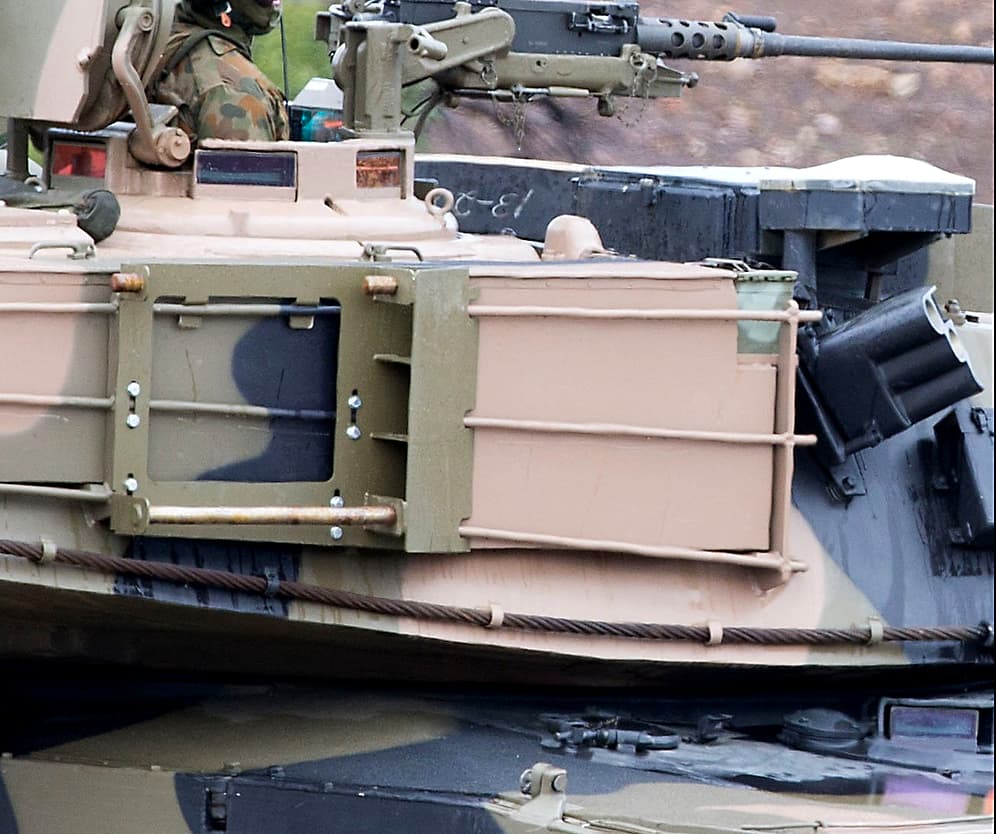
One thing to remember is that the M1 uses live track.
This means that the end links of a piece of track laid flat on the ground will curve upwards (unless maybe if totally worn out).
This is actually visible in the phots of the real thing in this thread, the bottom link swings up slightly.
The section of track on the left below shows the natural angle between the links
Seen “in the wild”
The two links at the end lift off the ground
I see what Ryan and Gino are saying, but for a slacker like me I would be going for its close enough now to get the meaning across. All I would do is; add a small piece of old PE ( like a small square piece you can make into a right angle) to the outside edge of the upper end connector to simulate a mounting point and then a small piece of plasti rod on the end with a bolt on it …)
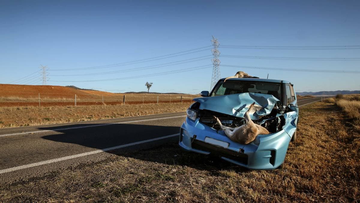
Wallabies are small. A Roo is not a small cuddly animal. A Red Kangaroo is as tall as some humans and head to tip of tail - much longer than any human:
“Males grow up to a head-and-body length of 1.3–1.6 m (4.3–5.2 ft) with a tail that adds a further 1.2 m (3.9 ft) to the total length”