It gets even more tedious now… I can’t get onto the FC model trend web site to even order these damn exhaust elbows… my patience is now wearing thin…
Well, I can get on the FC model trend site now, that’s something…
Now, back to the pain…
Just when I thought it couldn’t get any worse…
Anyone see the problem…?
No ?? …
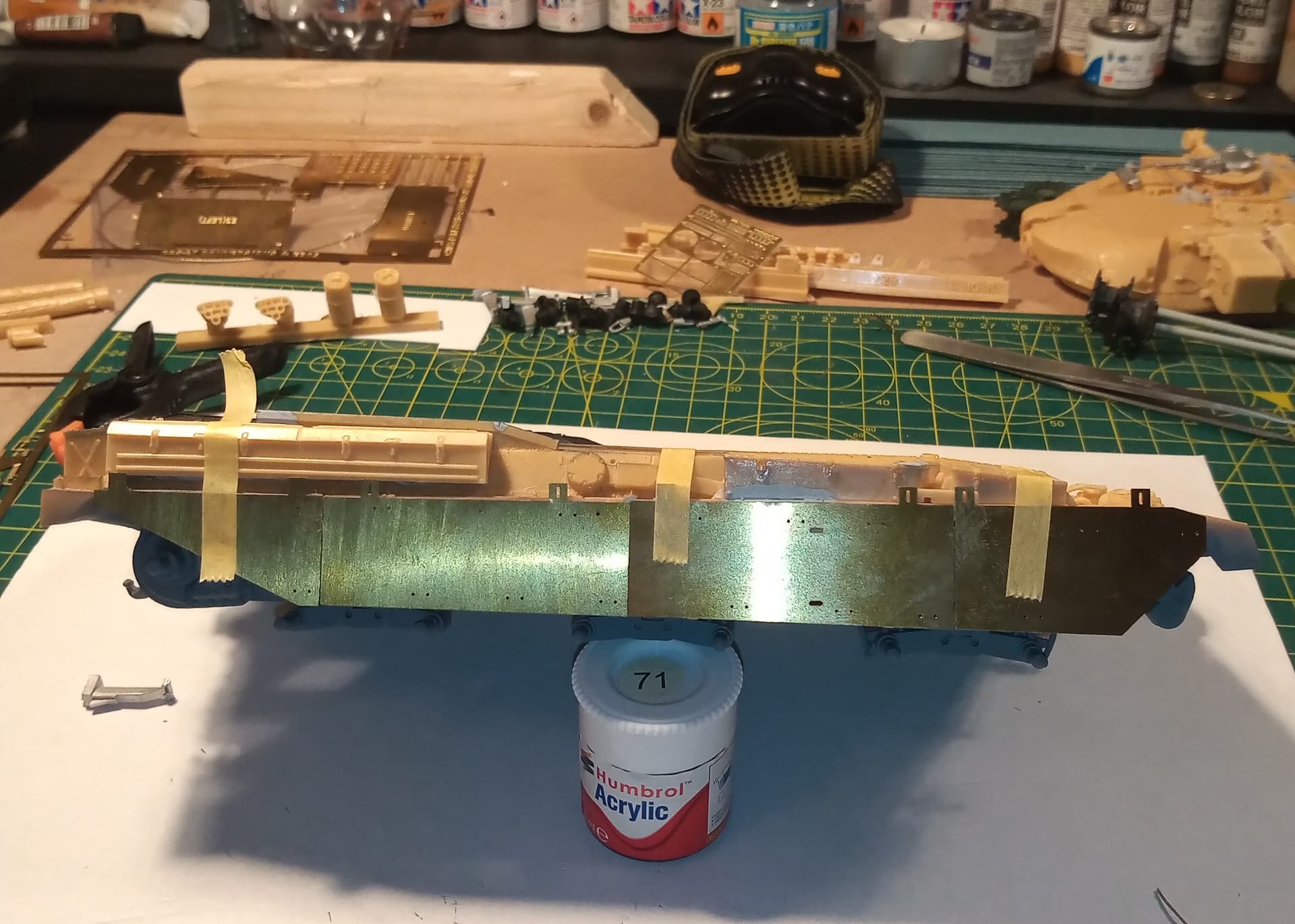
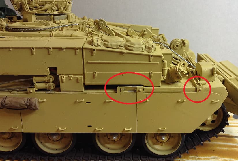
Well, the boz plates don’t fit…

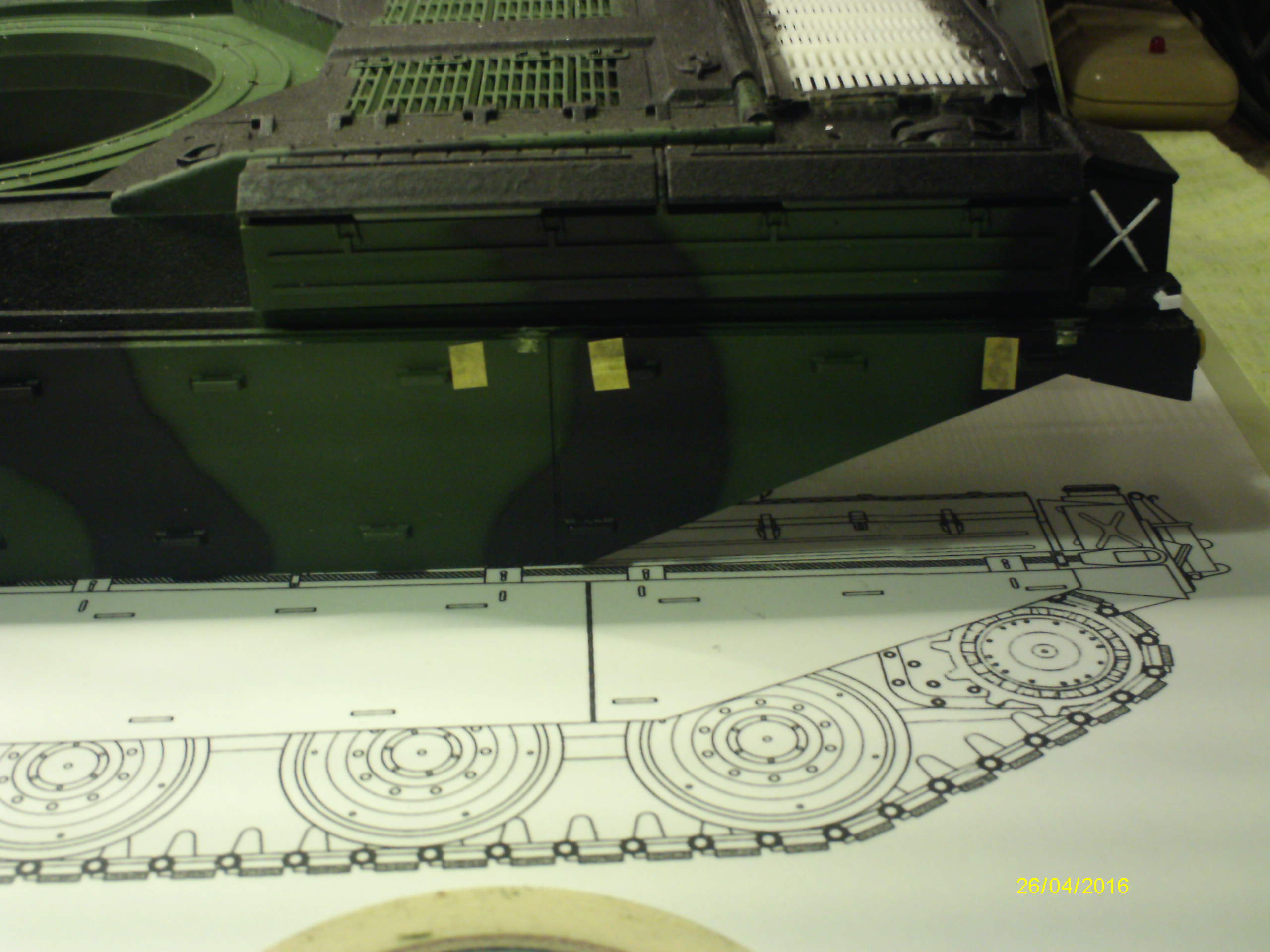
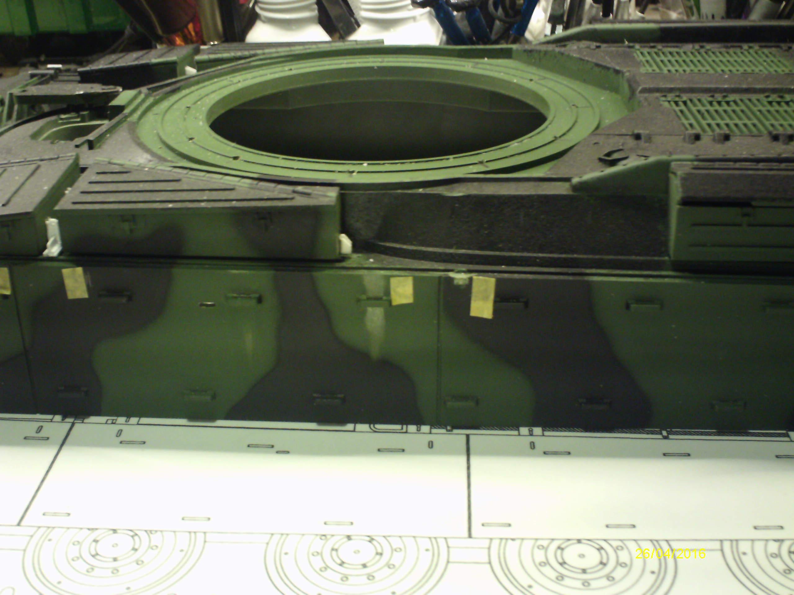
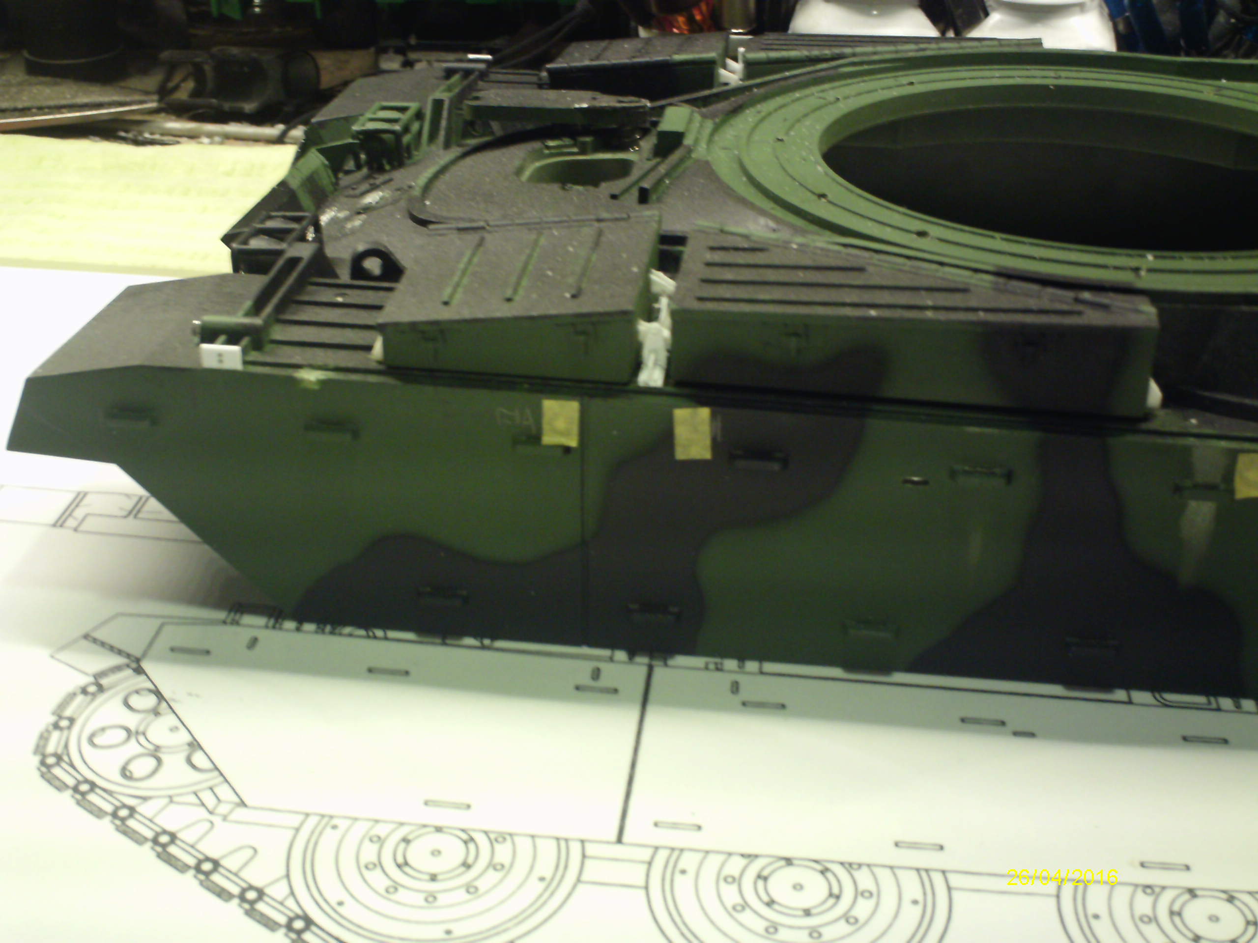
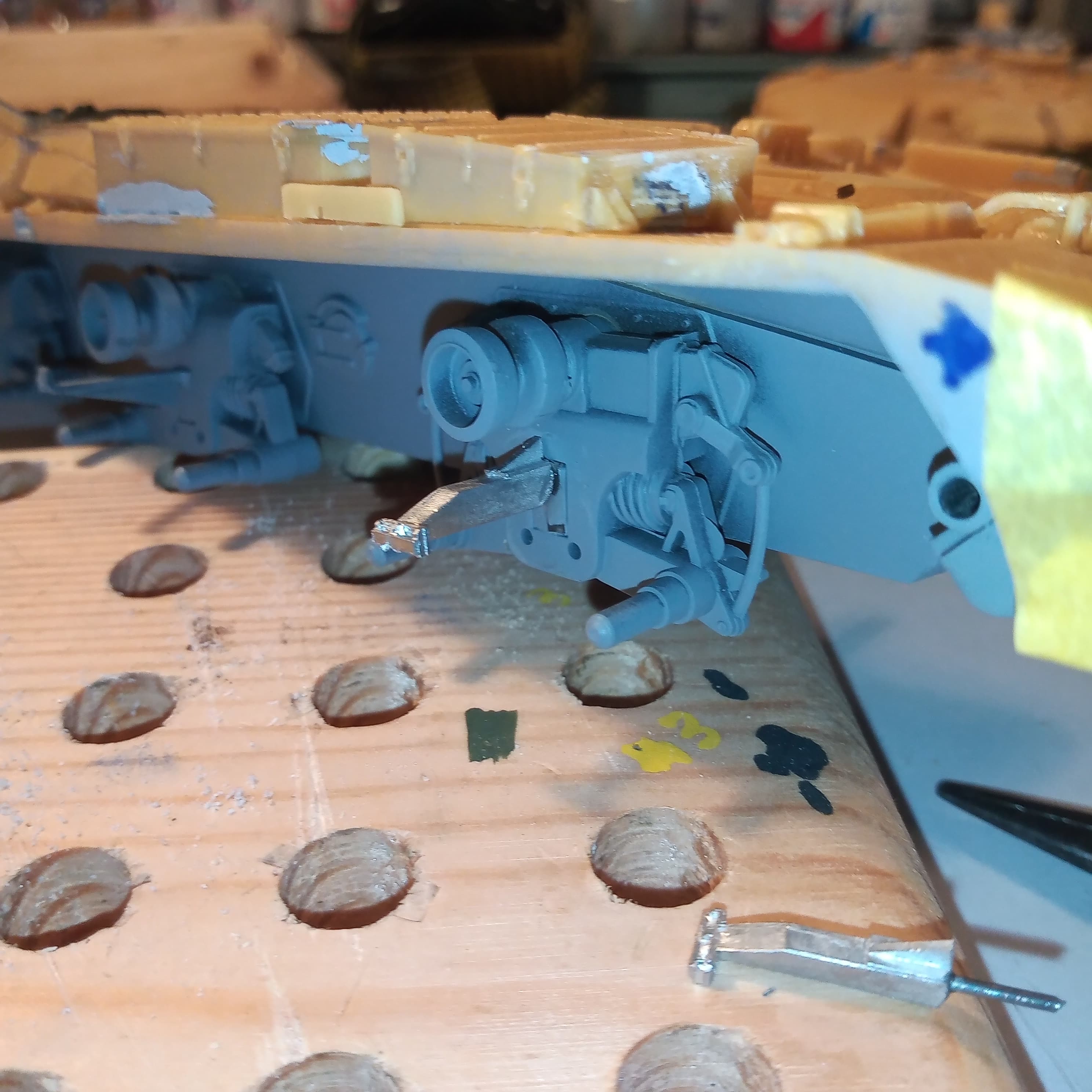
I wanted to make sure so I CA’d a strip of plastic to the rear and taped them in position with the rear plate in its correct location if it were fitted…
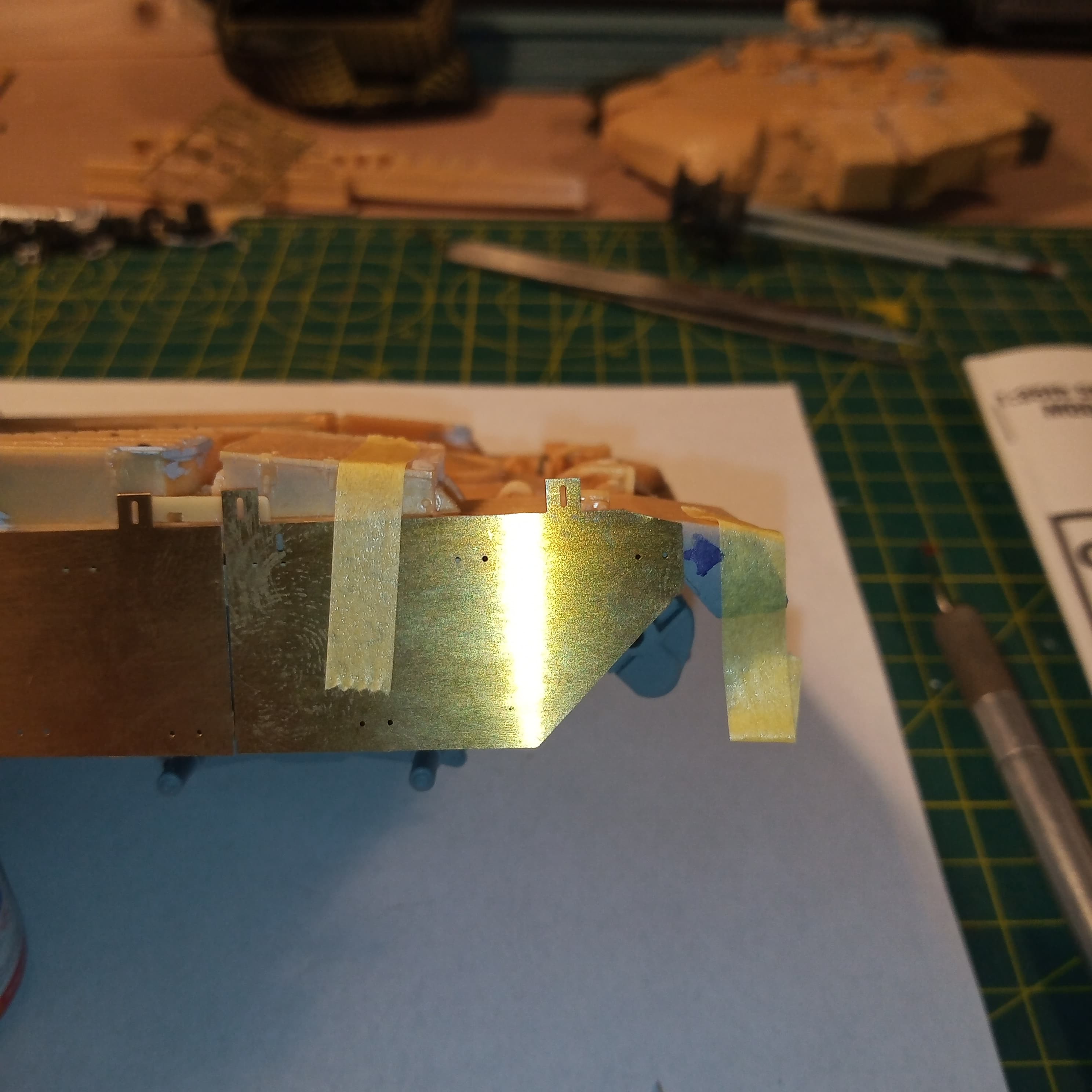
Then, when you get to the front…
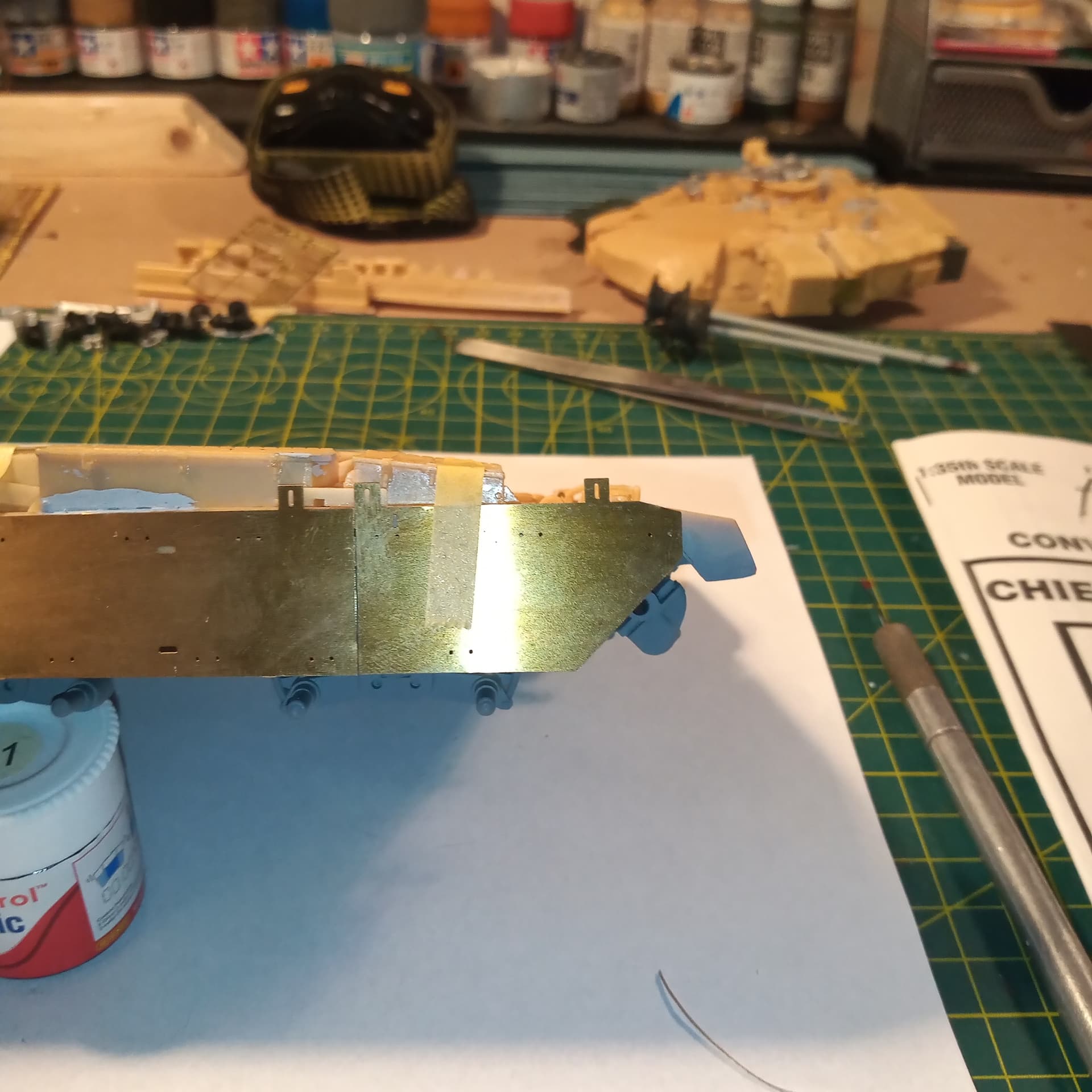
You have the obvious gap at the front before it gets to the front mudguard…
It’s about 4 to 5mm to short…
God only knows how that has happened.
This is where it should actually lay on the mudguard where the blue arrow meets the masking tape.
There is no fix for this. All I can do now is leave the No1 Boz plate off on both sides.
However, to do that I will need to remove the Tamiya Boz plate arms from the front wheel station on both sides and replace them with the white metal Accurate Armour ones and then add the AA front boz plate arm that goes straight onto the hull, which isn’t on the Tamiya kit… Joy
I will not let this beat me… But I’m dreading the next curve ball this chucks at me … And there’s bound to be one…
5 Likes
Be British John…stiff upper lip and all that…
1 Like
Plastic card replacements?
I think I need a stiff JD and coke… Without the coke lol
1 Like
Hi Johnny
I feel your pain. Luckily on my Chief, the skirts are part of the upper hull, though the moulded attachment points look nothing like they should & are out of place.
Unluckily, the footman loops on the skirts are all solid, They can be drilled open, but long involved & tricky job.
Mal
4 Likes
Excuse me butting in Mal, but to be honest, on the real thing these loops are small enough; I reckon by moulding them closed up the casting designers have probably done as well as they can given the scale limitation. I’ve seen some renditions on models sporting plates (by modellers modifying the item) where quite frankly, the real thing, were it ever scaled up, would have been around 6" long and 3" proud (of the plate).
I feel the secret is in the painting whereby a dark wash will fill the recess (if you get what I mean) and then highlight the loop with a little dry-brushing.
I must just confess that I am a fairly lazy modeller!
2 Likes
Or just use the tip of the blade to score lightly and make a depression the pin wash paint will fill.
I didn’t have this issue with the ARRV as the plates are well forward onto the side of the front mud guard, however I found my sets did not align correctly on both sides.
This how they are on that vehicle:
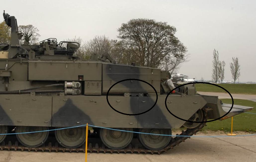
Lining up the front plate correctly with the first mount point on the hull and working back, I got a gap at the rear that should not be there:
Lining up the rear plate on the other side the same distance away from the end and moving forward, I ended with the front plate mounting point forward of the moulded in detail, whereas the other side lined up!

… same as you the mounting plate between plate 1 and 2 is too short and slots don’t align. I drew the line at going back and fixing these. Note the front location point lining up with the moulded detail too).
5 Likes
Won’t be doing that route… No card thin enough to match the PE and not ordering or driving to get some. Then there’s the cutting, sanding alignment of all the other bits and bobs …life’s to short… Will post the remedy I’ve done and where I’m at with it in a mo.
1 Like
It’s a shame they get things like that wrong Mal with those top mounting plates. On a scale that size there is so much scope to get those sort of details right and make it a great kit.
That’s a lots of drilling Mal… But good on you for doing it, I think I would of gone down Peters route and scored the top part to let a wash fill it… But we’ll done 
1 Like
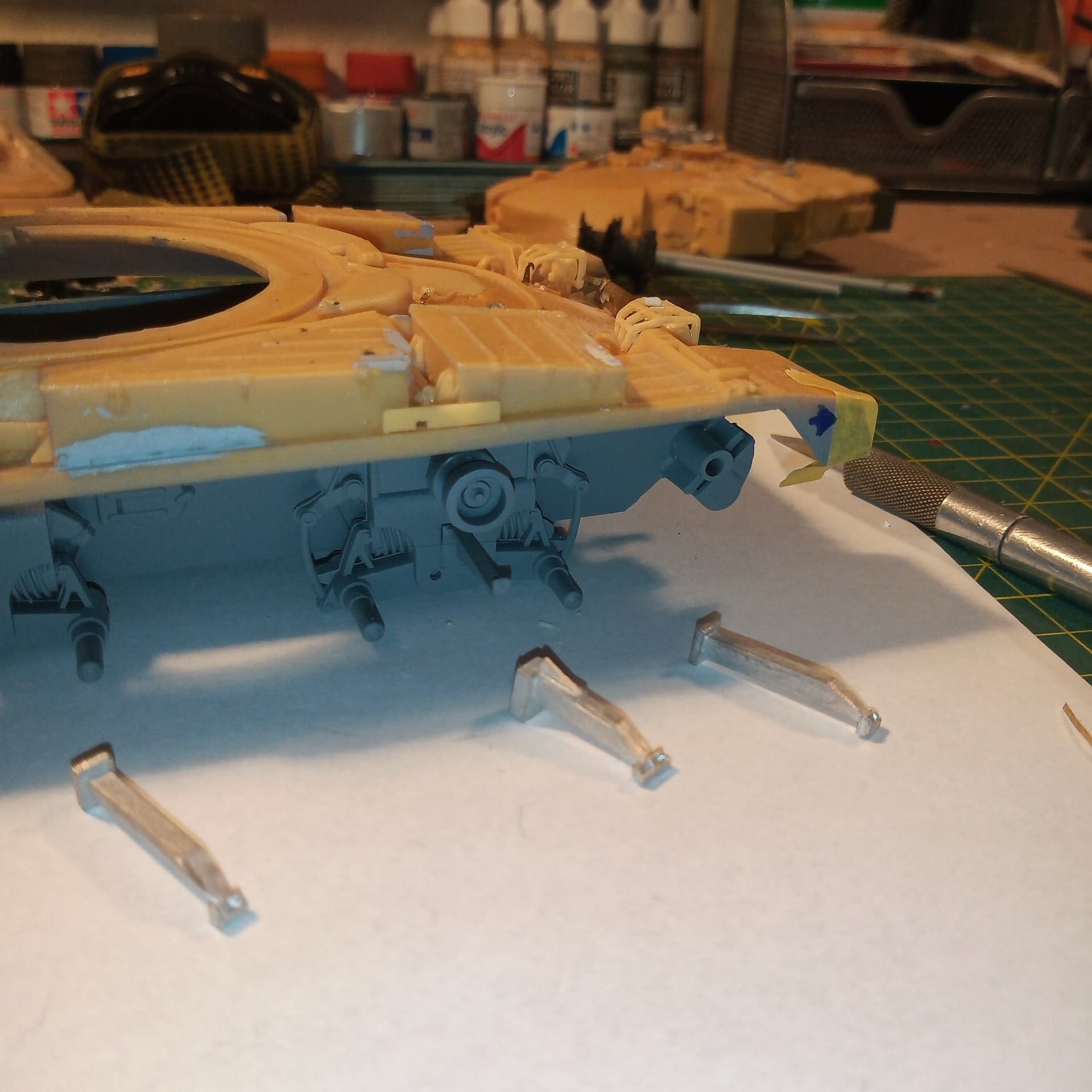
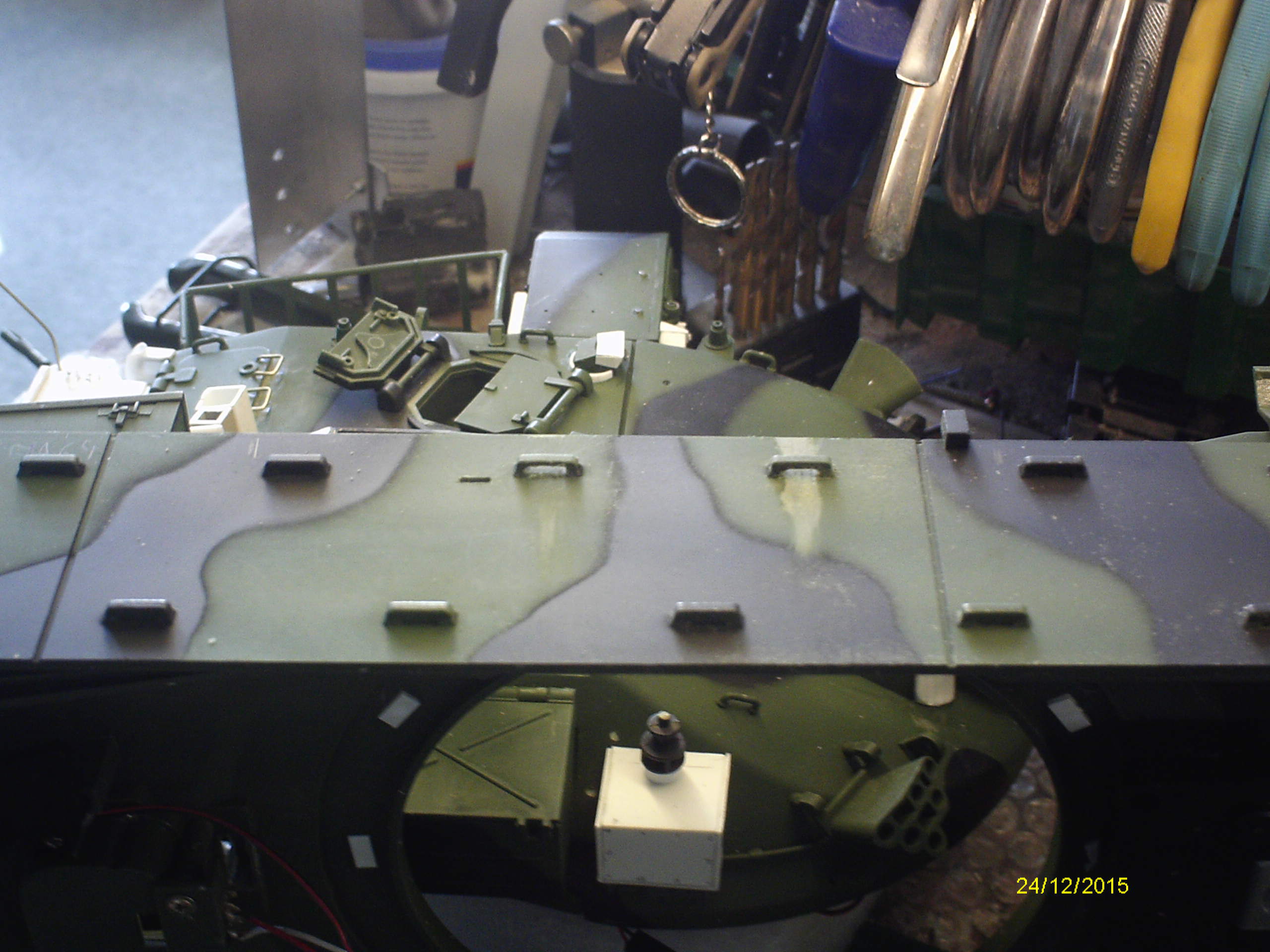
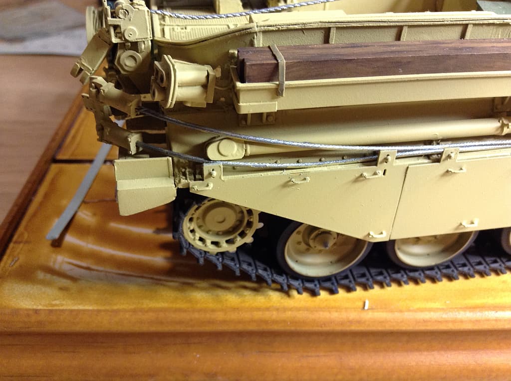
Did the 2 front wheel station arms.
In actually only took about 15 min to do both which I was happy with .
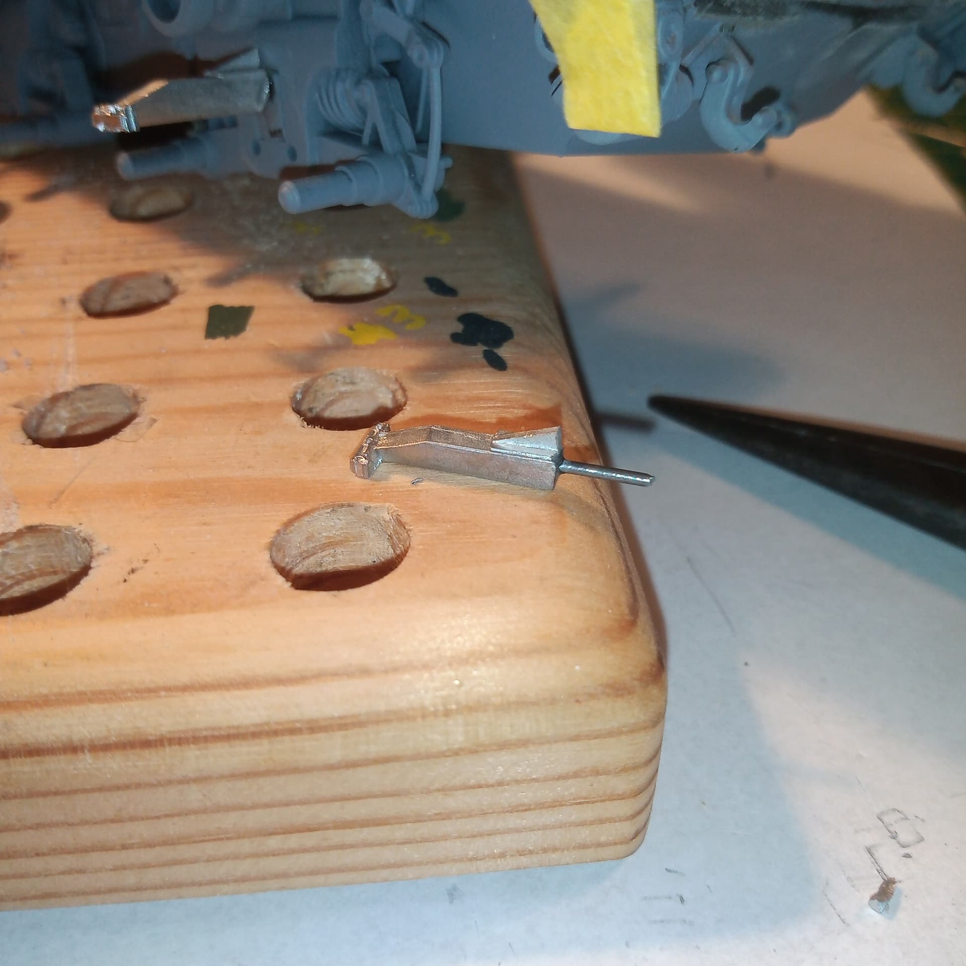
Basically broke off the plastic kit arms, sanded that area smooth, then cut the back off the white metal AA arms and drilled a small hole in the back and another on the wheel station where the arm would go and super glued them in.

Will do the front arms that goes in between the TA wheel and the 1st road wheel tomorrow using the same method.
5 Likes
I had to make sure the rear plate on mine is mounted in the correct position as the front ones are so out and even if I moved them forward, the plates for the upper mounting bolts will be well out of alignment… If I hadn’t of crewed one I probably wouldn’t of noticed it to much… But to me once I knew it was like a giant aiming mark…
1 Like
Now check the plates and see if the join at the bottom of the plates goes over the support. On the ARRV, the support is about 2mm inside the join. No matter where you locate the plates, only one rests up against the support…
Can I make a suggestion, something I wish I had done, span a strip of thin styrene right across the back of the plates to make a single glued together section. It will help you align the plates with each other and make adding them to the hull a hell of a lot easier…
2 Likes
Hi Johnny
That was an experiment to see if I could do it - I wasn’t looking fwd to the alternative - cutting them all off & replacing with wire. Though having drilled them out, the alternative looked a lot easier. The thing with drilling them - just get one wrong - bit out of place/dig into the plate - and you’d likely have to redo the lot.
Yes, it would have been nice if the model was accurate, but no challenge in that.
Mal
1 Like
Yeah both sides tested and everything lines up  …
…
And someone had already mentioned about the styrene strip across the back to make things easier when putting the plates on. This has seriously put me off resin though … I think from when this is done the only resin I’ll be touching is stowage sets or accessories
2 Likes
@Johnnych01 A soft voice whispers in your ear, “Order the new Meng kit…”
1 Like
Some good news for once…
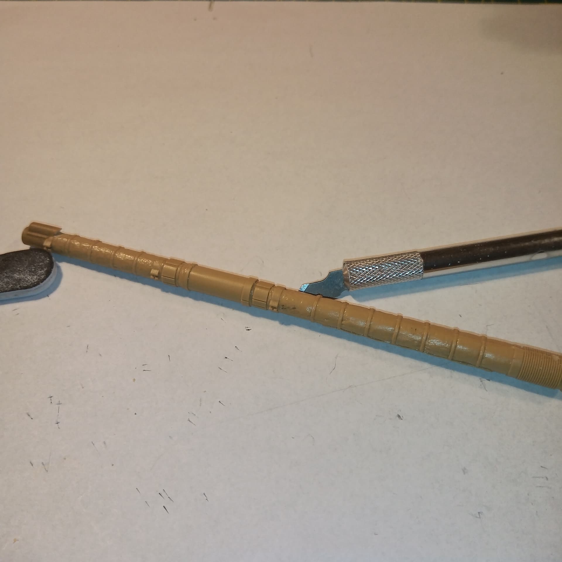
The L11A5 arrived courtesy of @frank , very appreciated…
Will begin trimming the turret end of the barrel so it fits the Stillbrew housing …
3 Likes
Barrel is now trimmed at the mantlet end which required the razor saw to cut back how it’s made for the CR1 fitting and the seams scraped/sanded back along the joins.and then fitted to the turret.
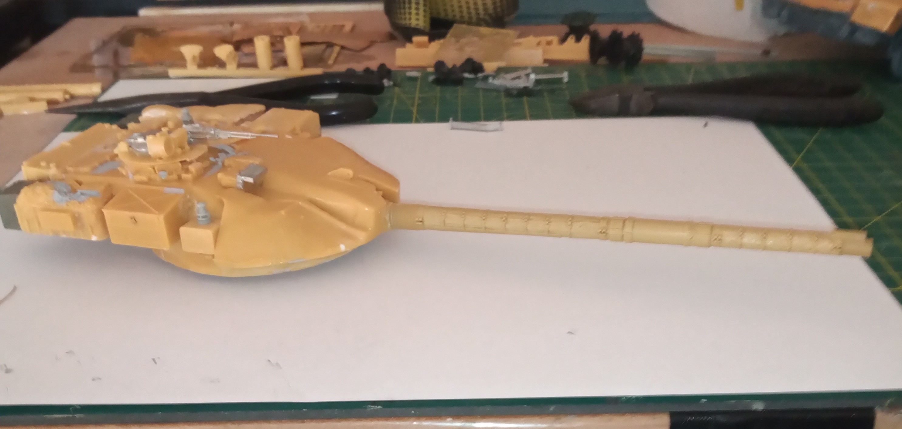
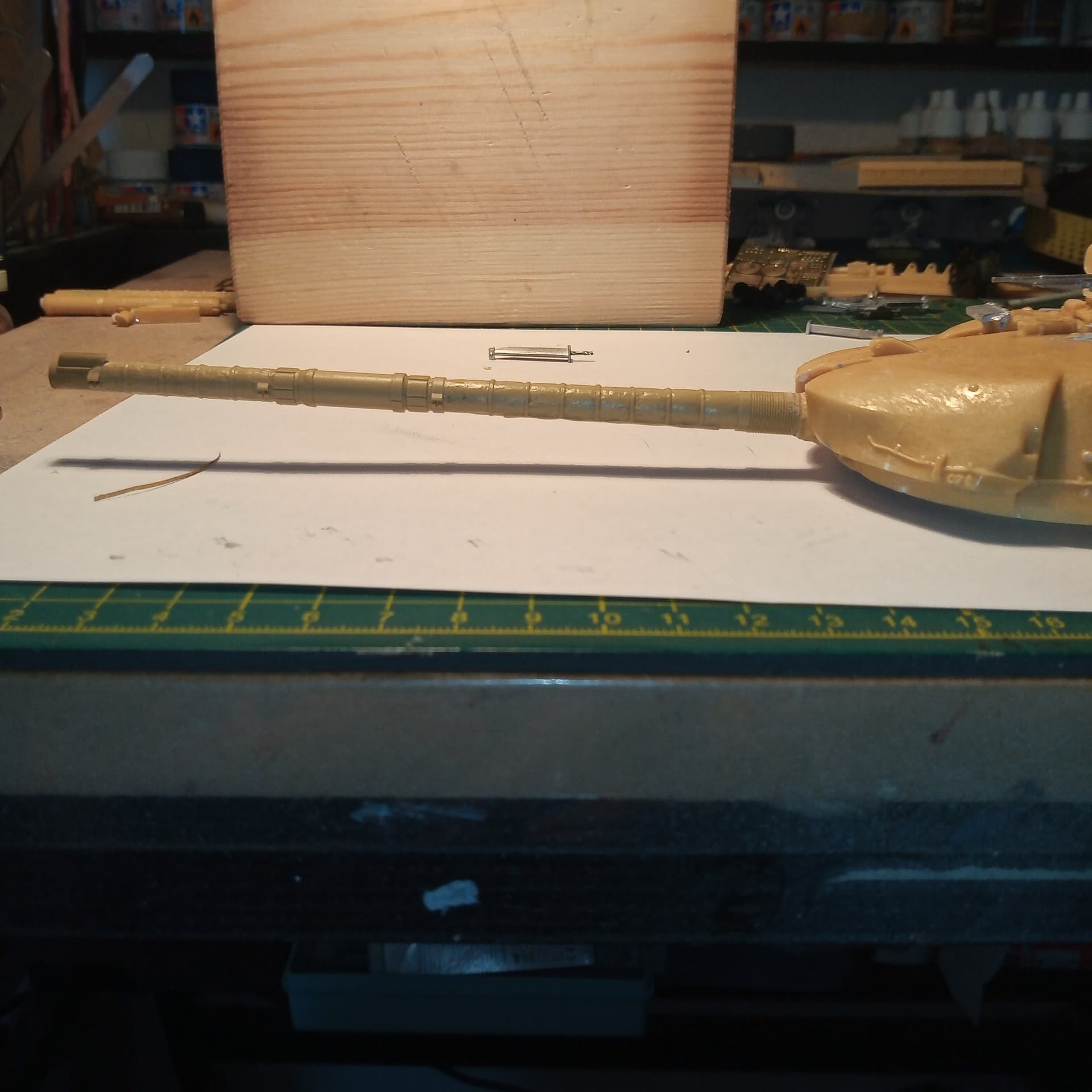
The way the barrel area has been molded onto the turret gives it a slightly elevated appearance, so you have to live with the fact the barrel cannot be moved that but it doesn’t make a big deal of difference overall.
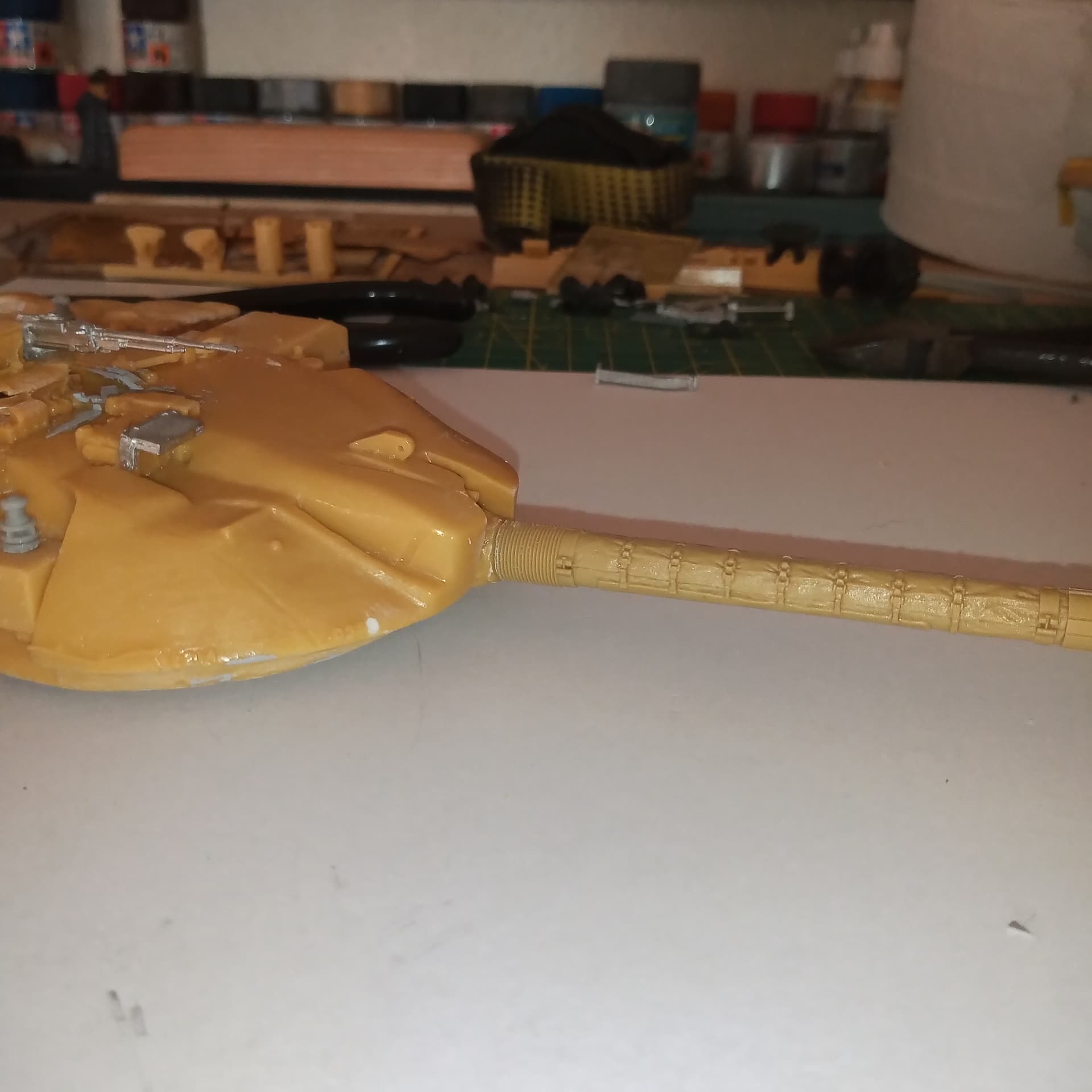
Last shot is just a bit of a close up showing the join from the barrel to the turret mold. It’s as flush as I could get it and I may try and tidy it up a bit later.
A very big thanks to @frank for the CR1 barrel which was a huge help, and got me back in the right frame of mind for the build.
8 Likes
That barrel looks excellent!
1 Like