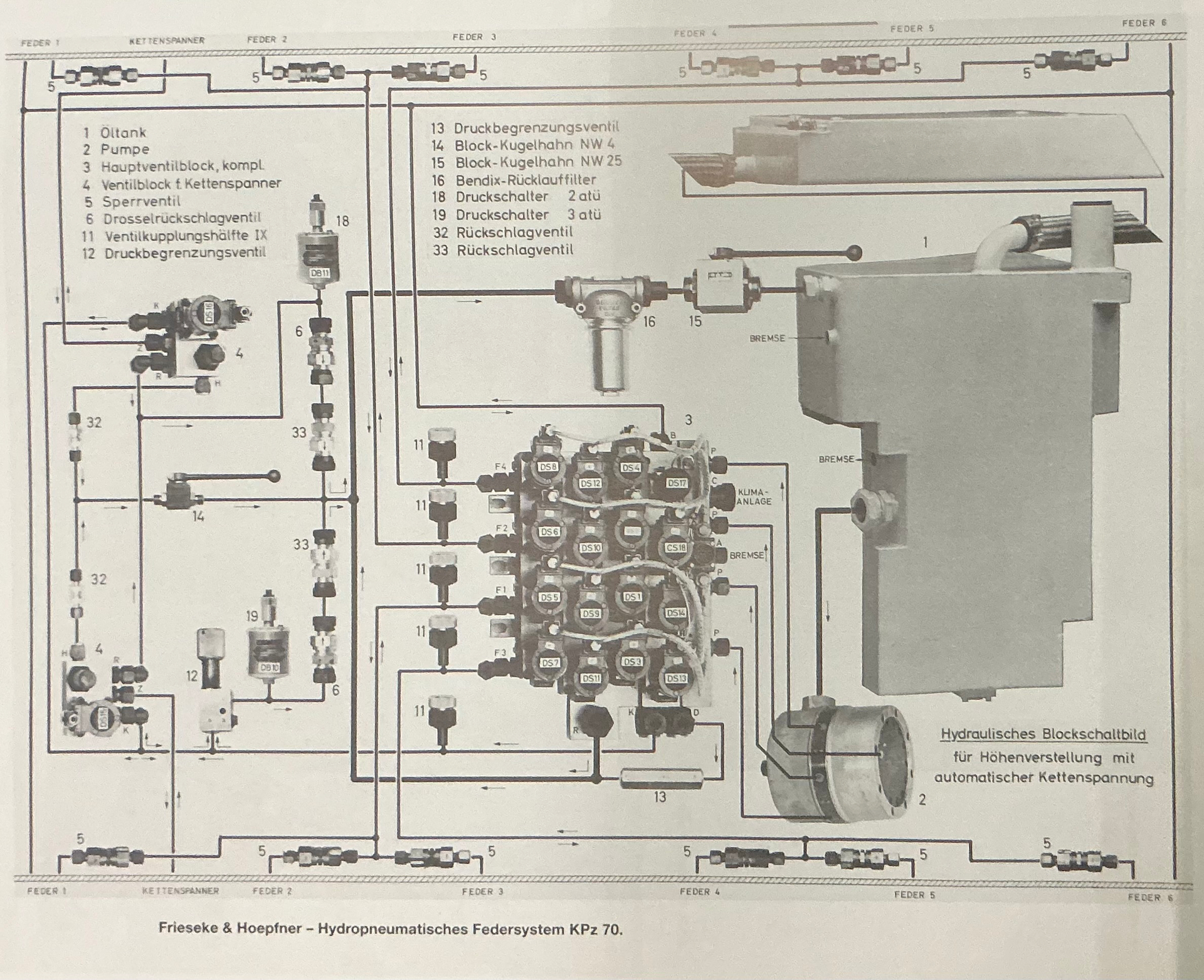
(Source: Waffensysteme Leopard 1 und Leopard 2 by Walter J. Spielberger (Stuttgart: Motorbuch Verlag, 1995; ISBN 3-613-01655-9))
This is for the KPz 70, not the VT 1, but since it used the same suspension, just with one roadwheel fewer, they probably adapted the hydraulics only as far as they actually needed to.
Thanks Jakko, but unfortunately it does not help. The VT 1-1 was based on the shortened Kpz 70 chassis and suspension, but the VT 1-2 had a completely different hull and suspension.
I appreciate you taking the time to post though. Cheers.
I thought the VT 1-2 also had a shortened KPz 70 hull? In any case, the suspension units look the same so I would expect the hydraulic system overall to use as many of the same components, too.
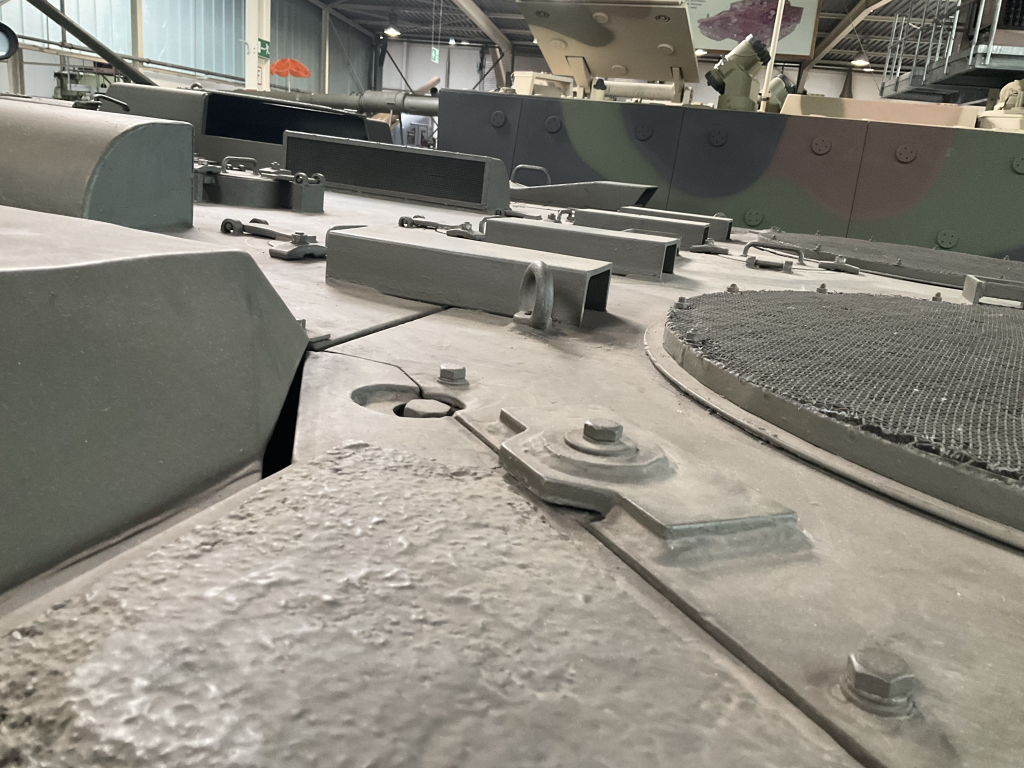
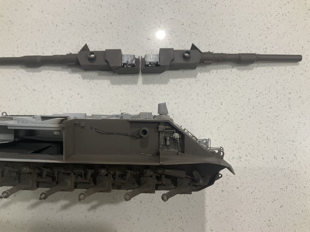
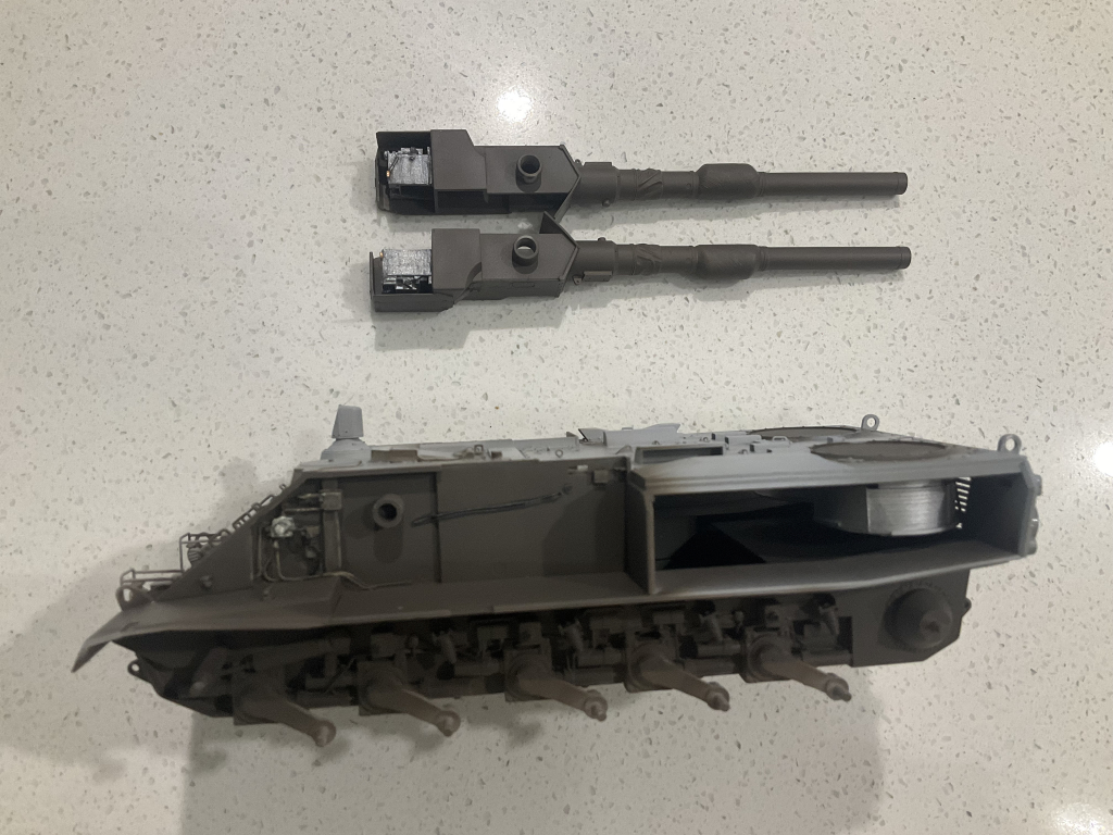
I stand corrected. You are right Jakko. Some of the hydraulic components are the same. There are no external feed lines on the Kfz 70 though - I just checked on the photos I took of the one at Koblenz.
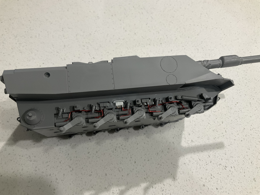
Maybe I could have just ignored the wiring and said it was the Kfz 70 suspension….. too late now.
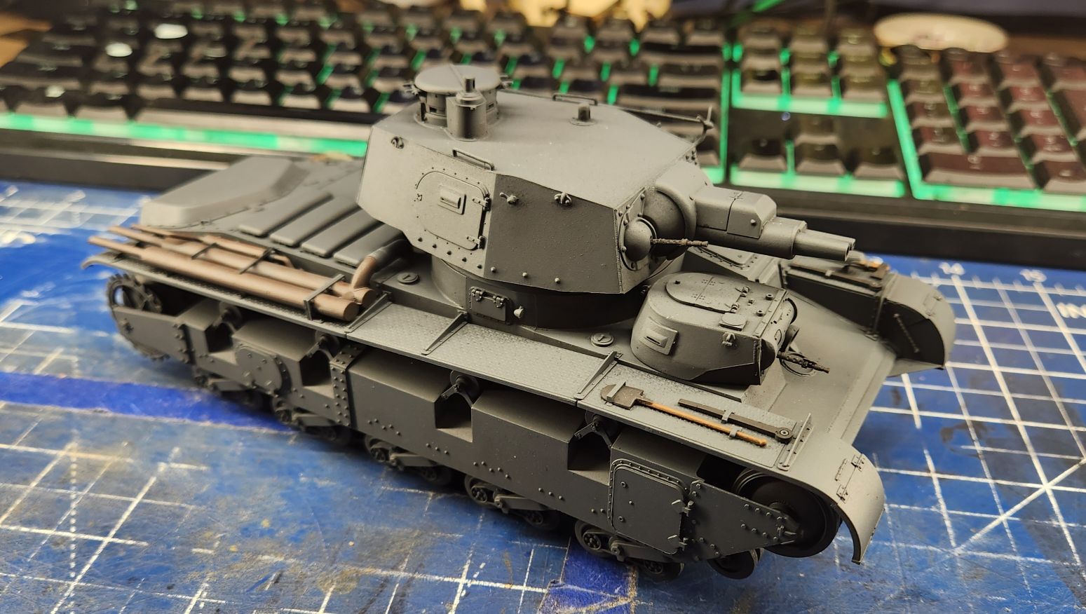
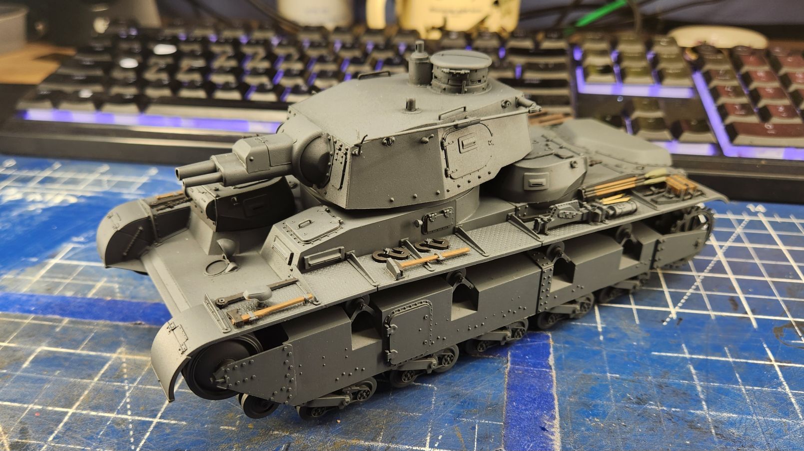
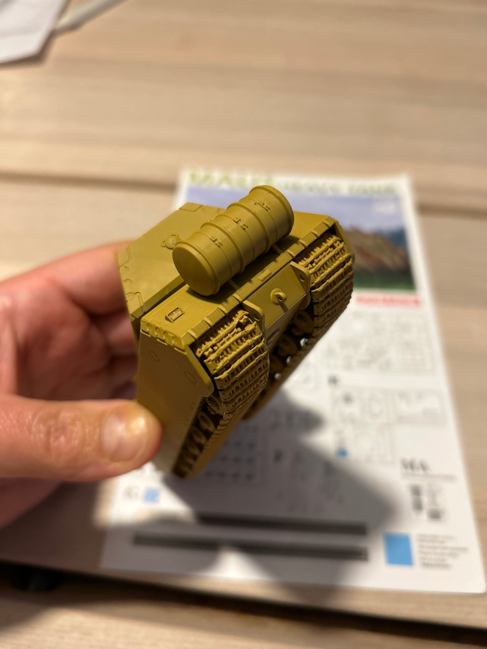
The DS tracks were 1 cm too short, so had to glue them in place. They reacted very strongly to a tiny amount of Tamika glue and almost broke. I do not remember that from previous encounters with DS tracks.
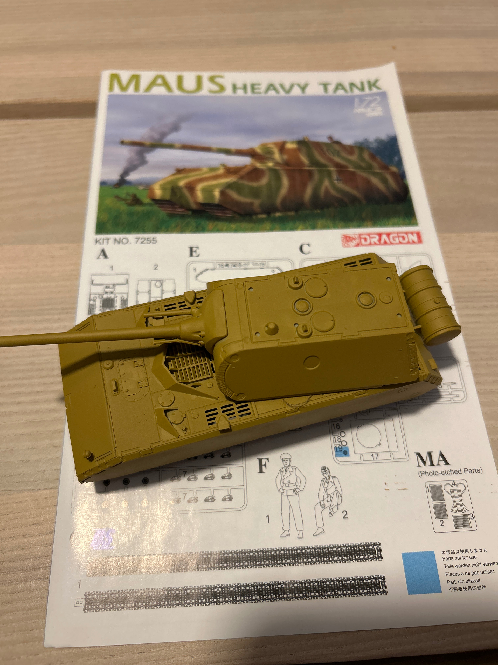
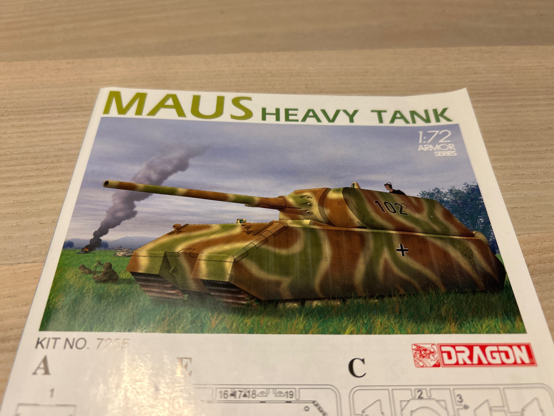
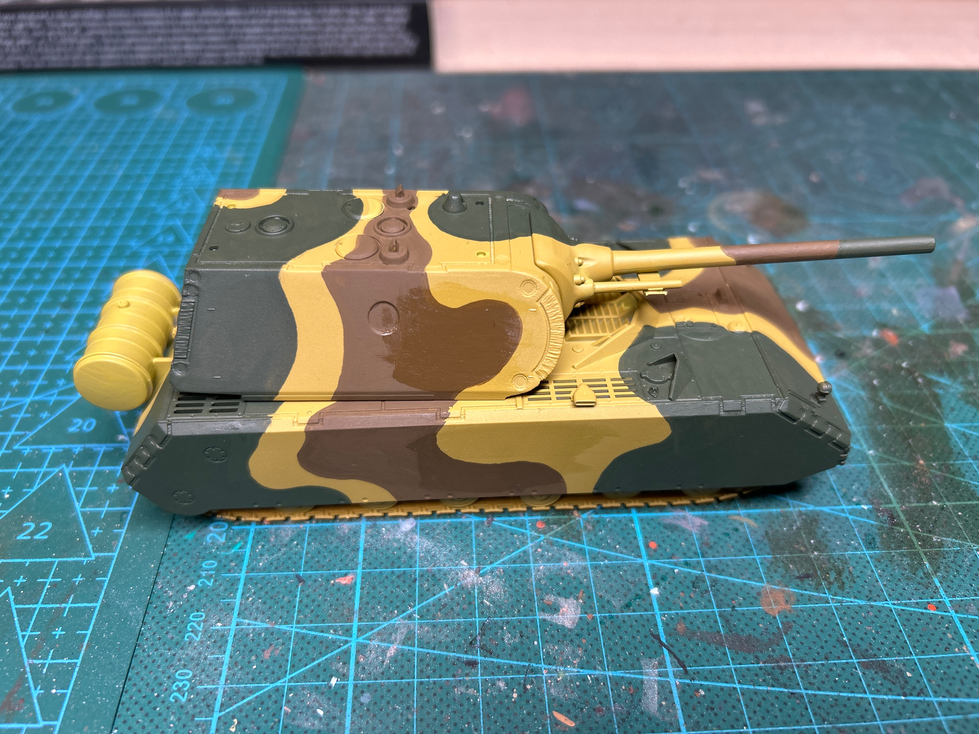
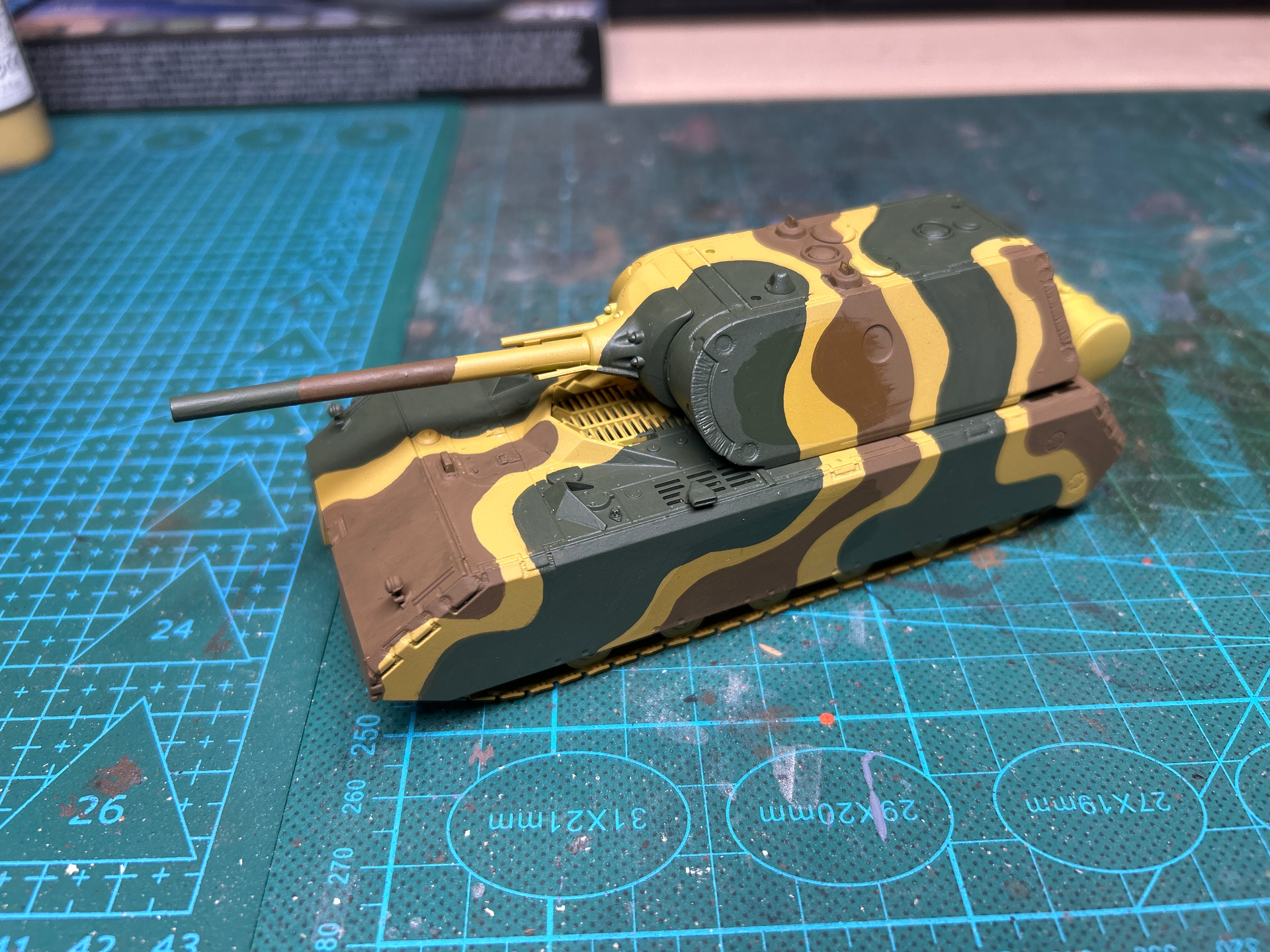
Next is painting - I am planning a scheme like on the instructions, but hard edged instead of sprayed.
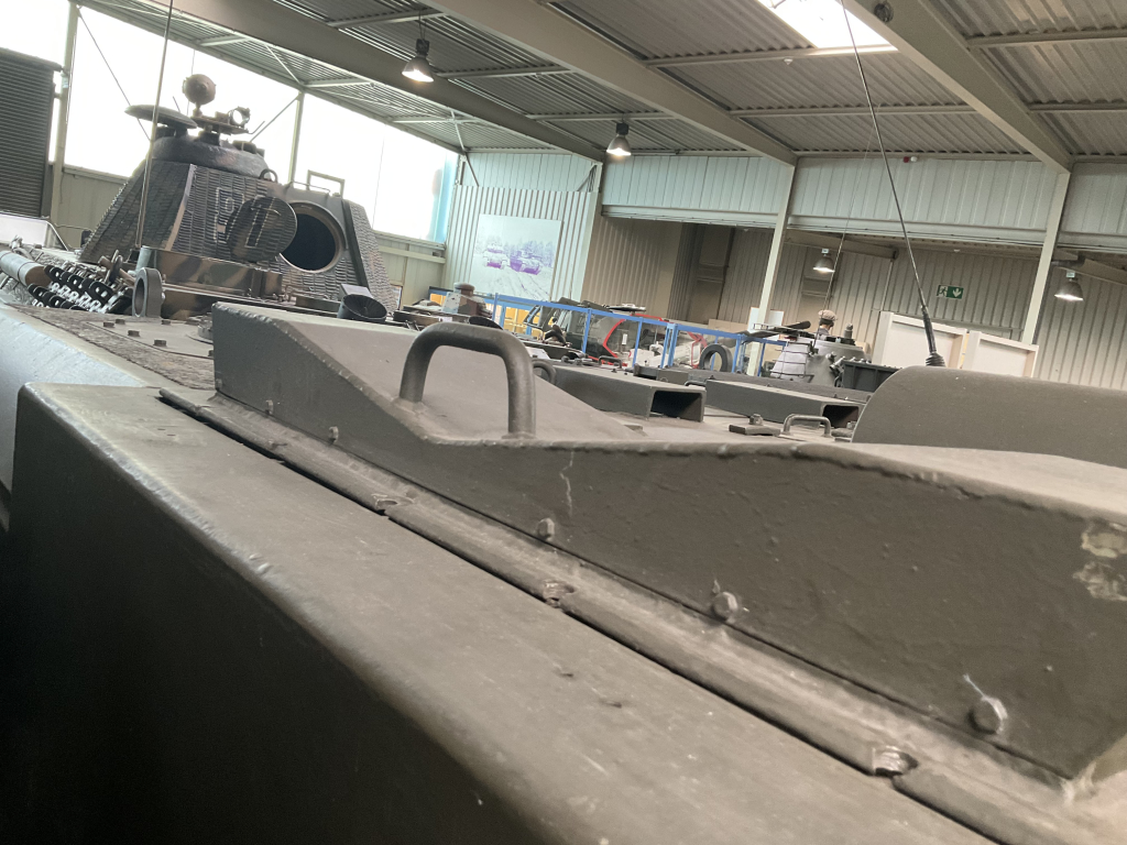
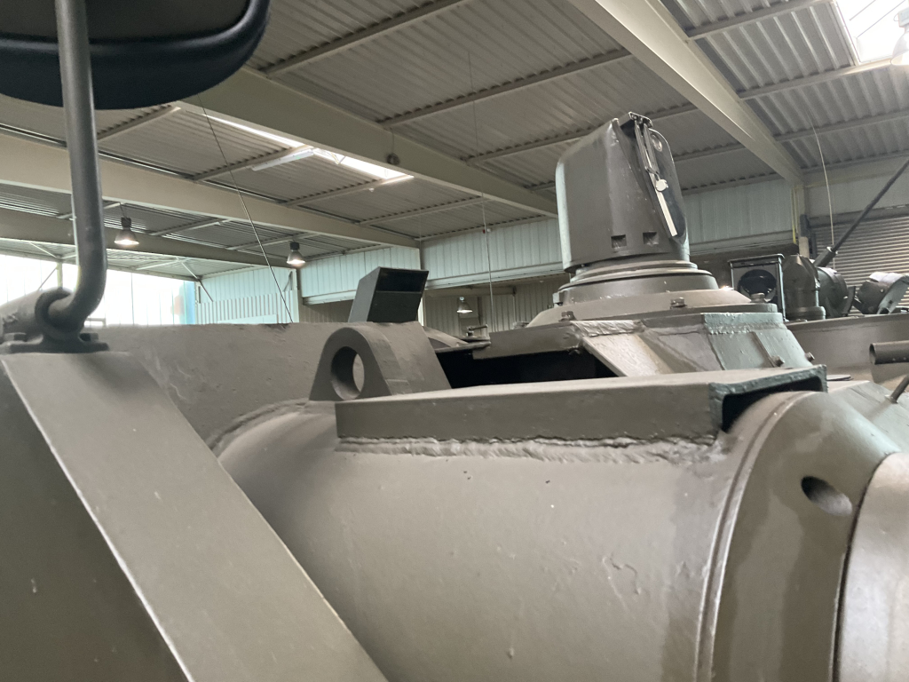
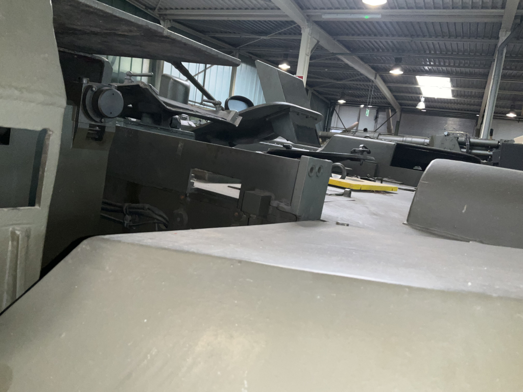
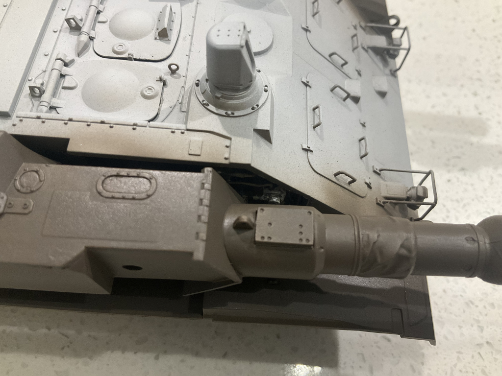
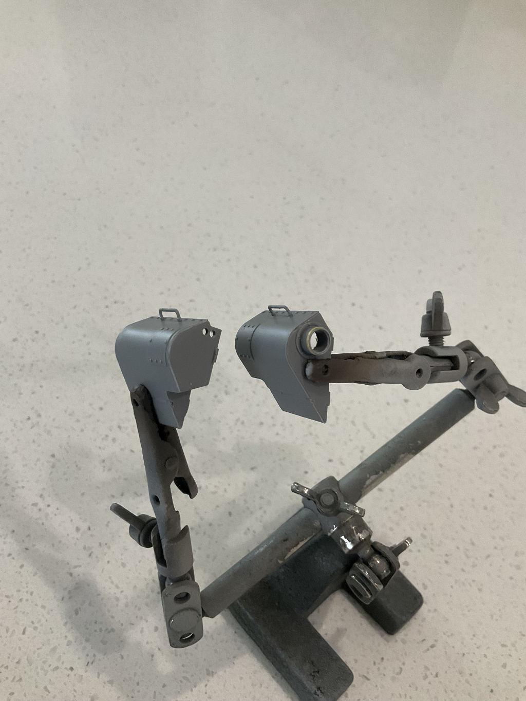
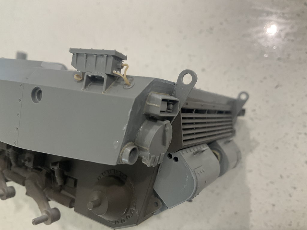
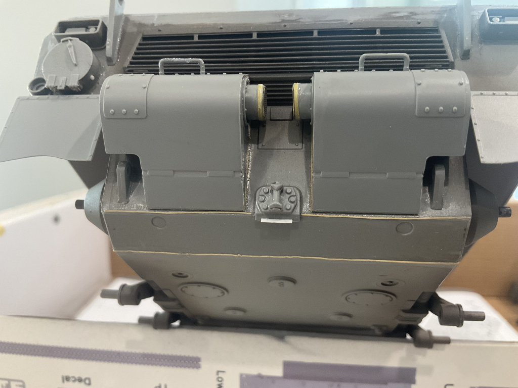
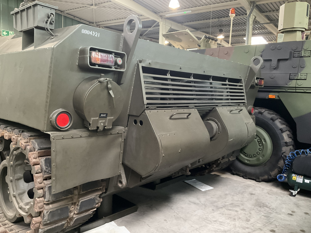
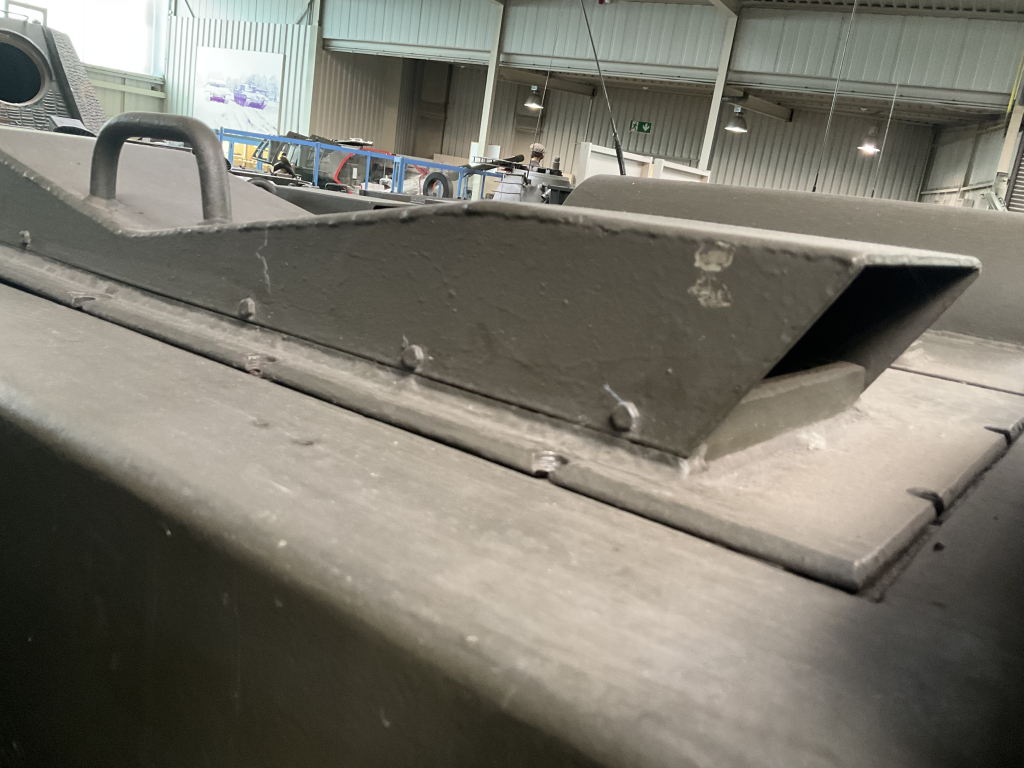
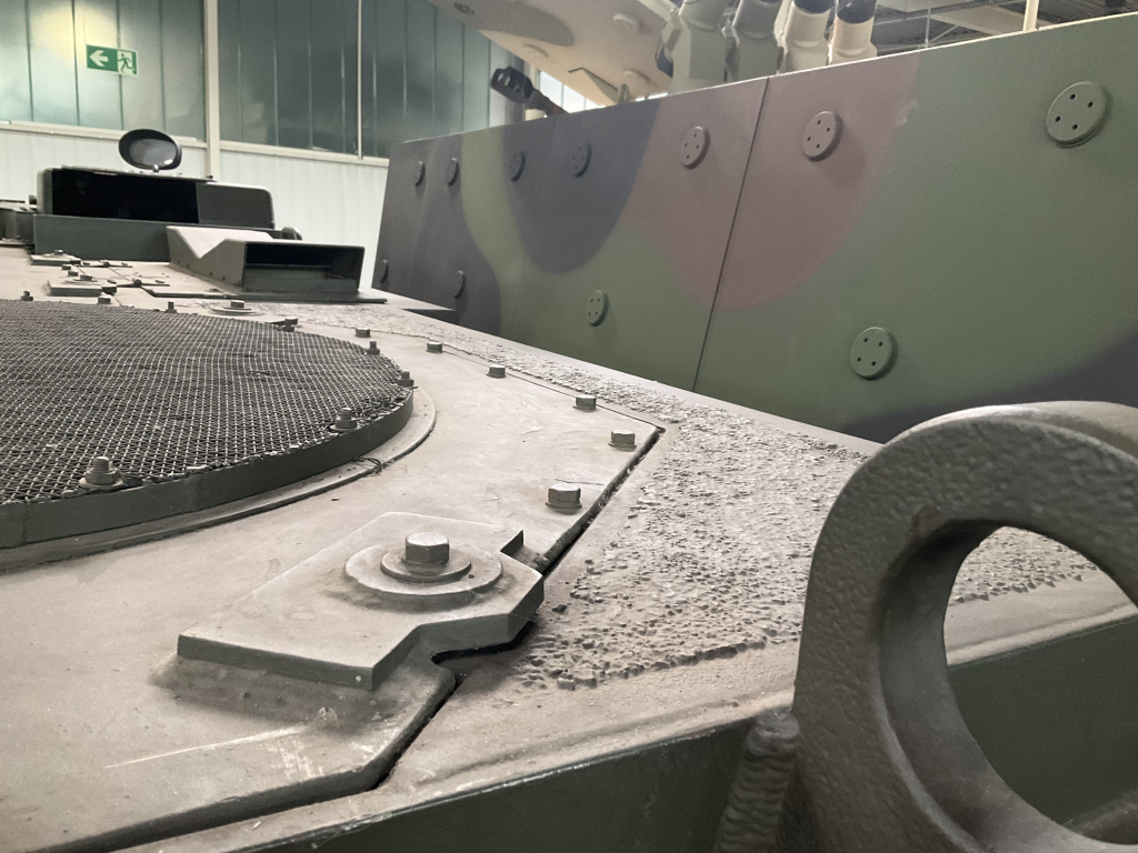
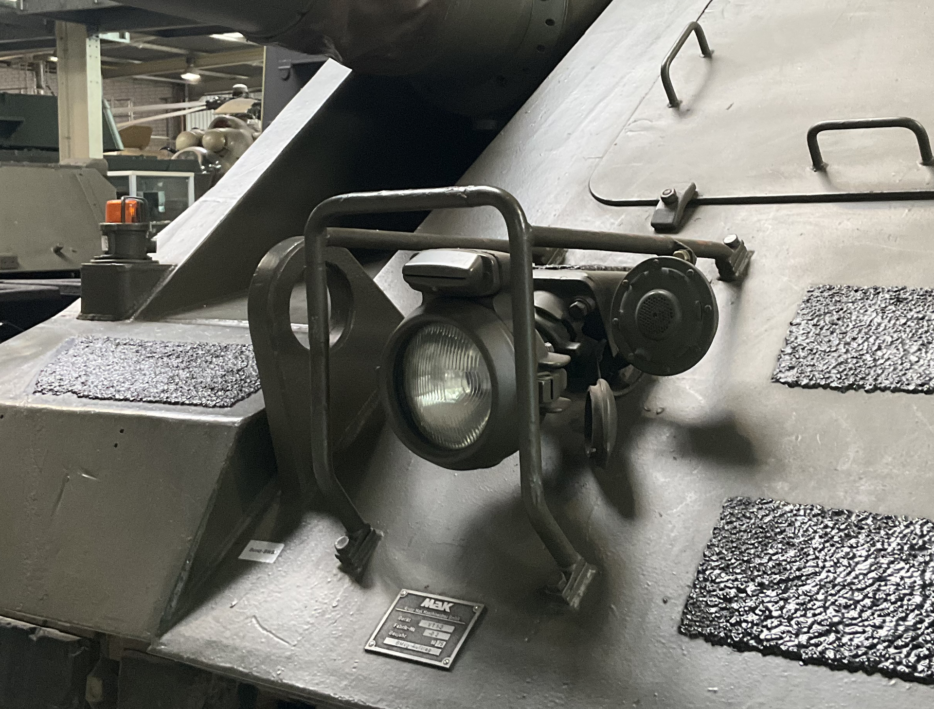
Here is where I am now and with some other pics for you Dave. If there are any pics of other areas you would like to see, let me know. Unfortunately I was not aware my camera had a focussing issue and a lot of what I took did not turn out…
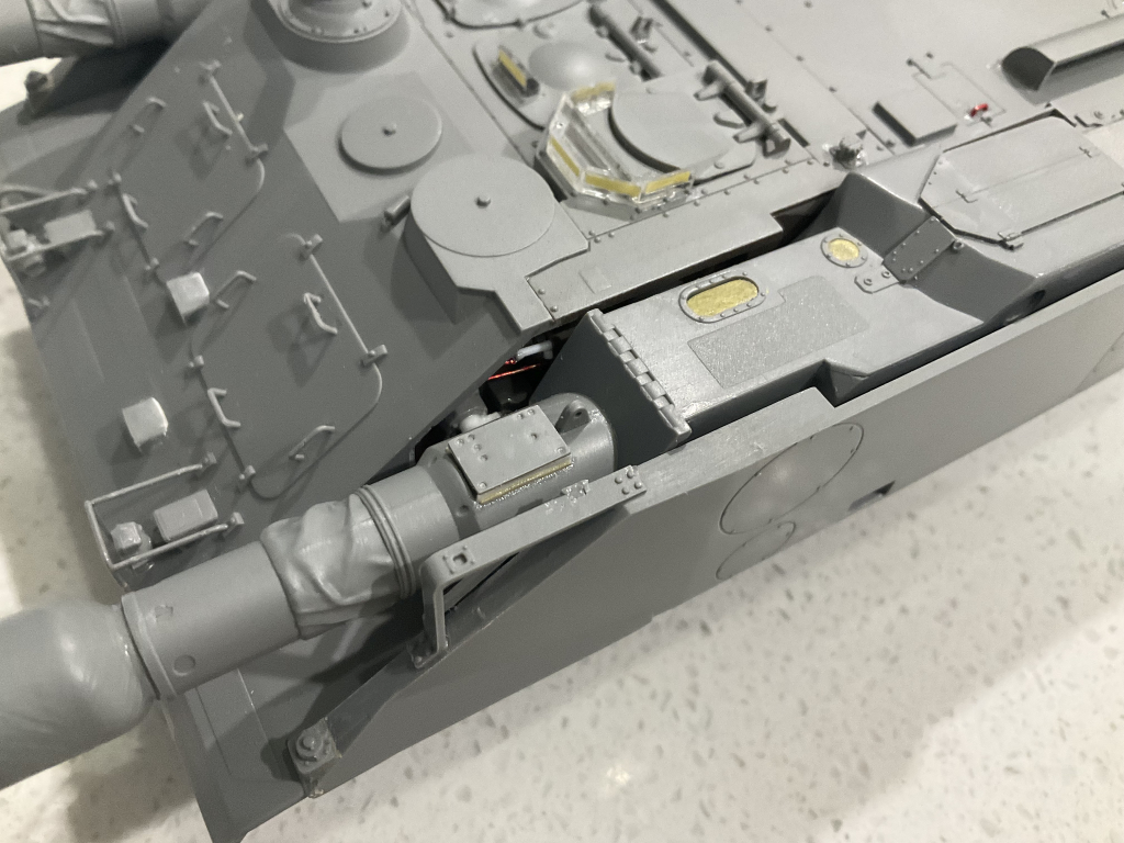
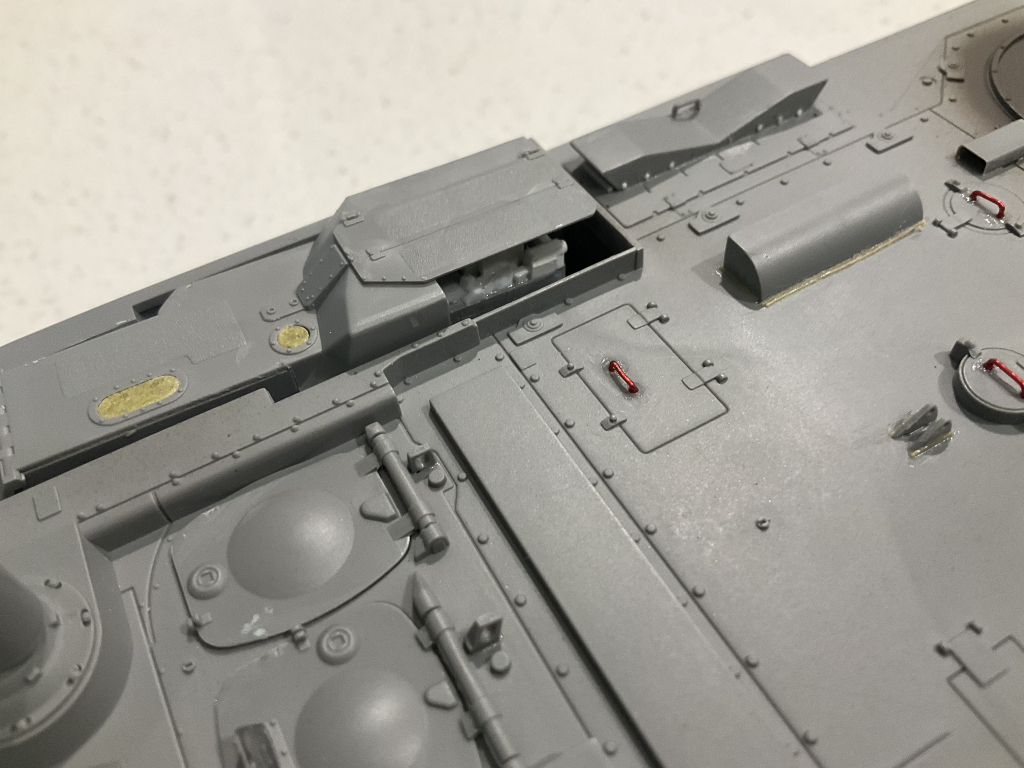
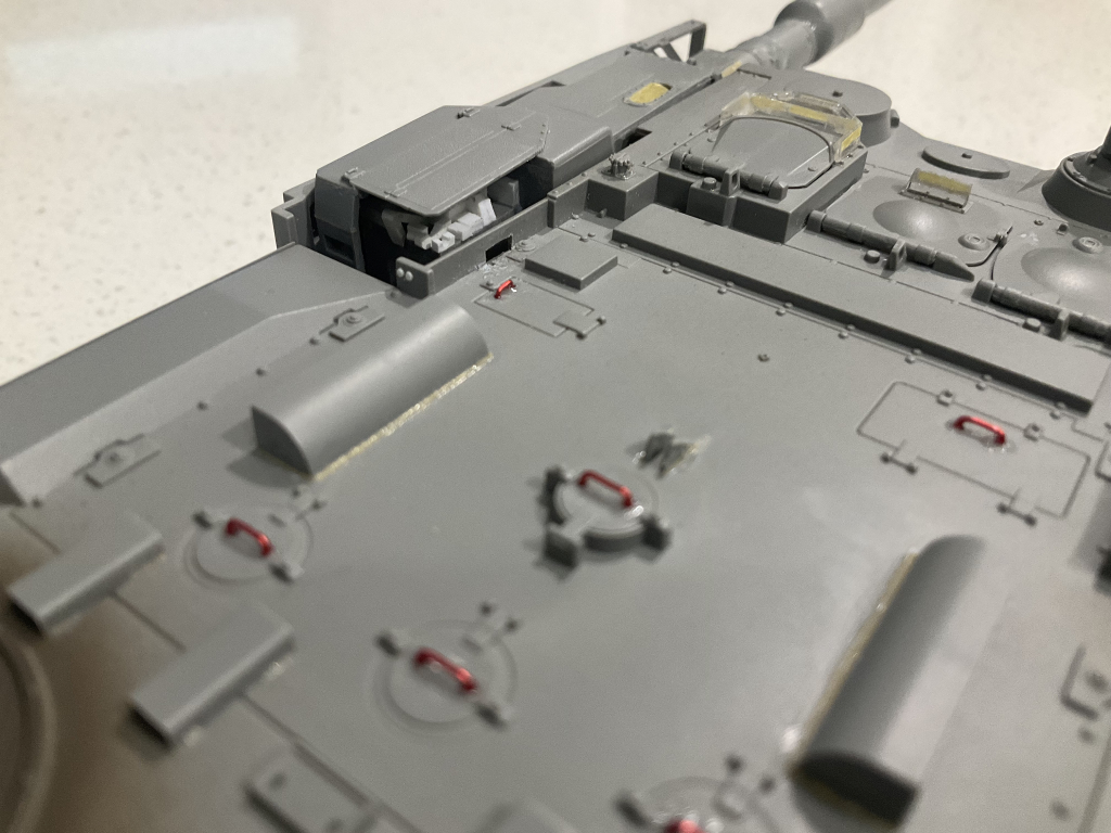
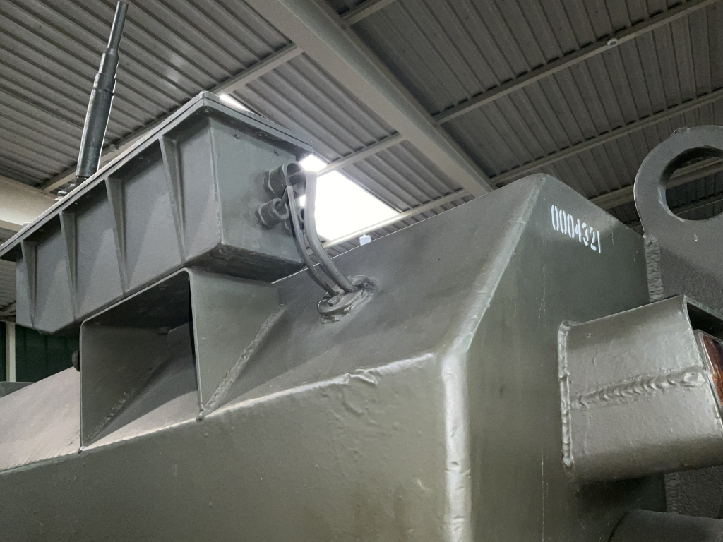
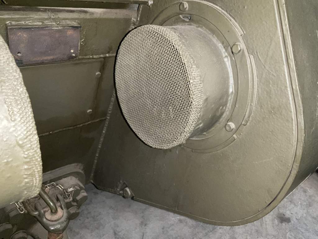
Getting close to the end of construction. Holes drilled out on the rear ‘pods’, plus the intake where the mesh goes has been drilled out to 5 mm. If you don’t, you see the thick cylinder wall through the mesh. Also added tape strip to simulate the mesh that goes around the side of the cylinder. Added bolts, weld beads and cables to the antennae mount. Added more weld beads to the hull and around the reflector housings, side of the tail light housings, etc, and a mounting plate under the pintle:
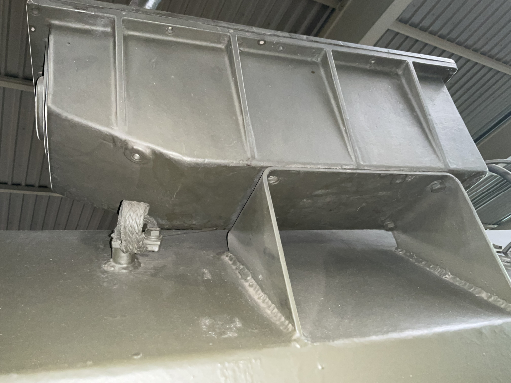
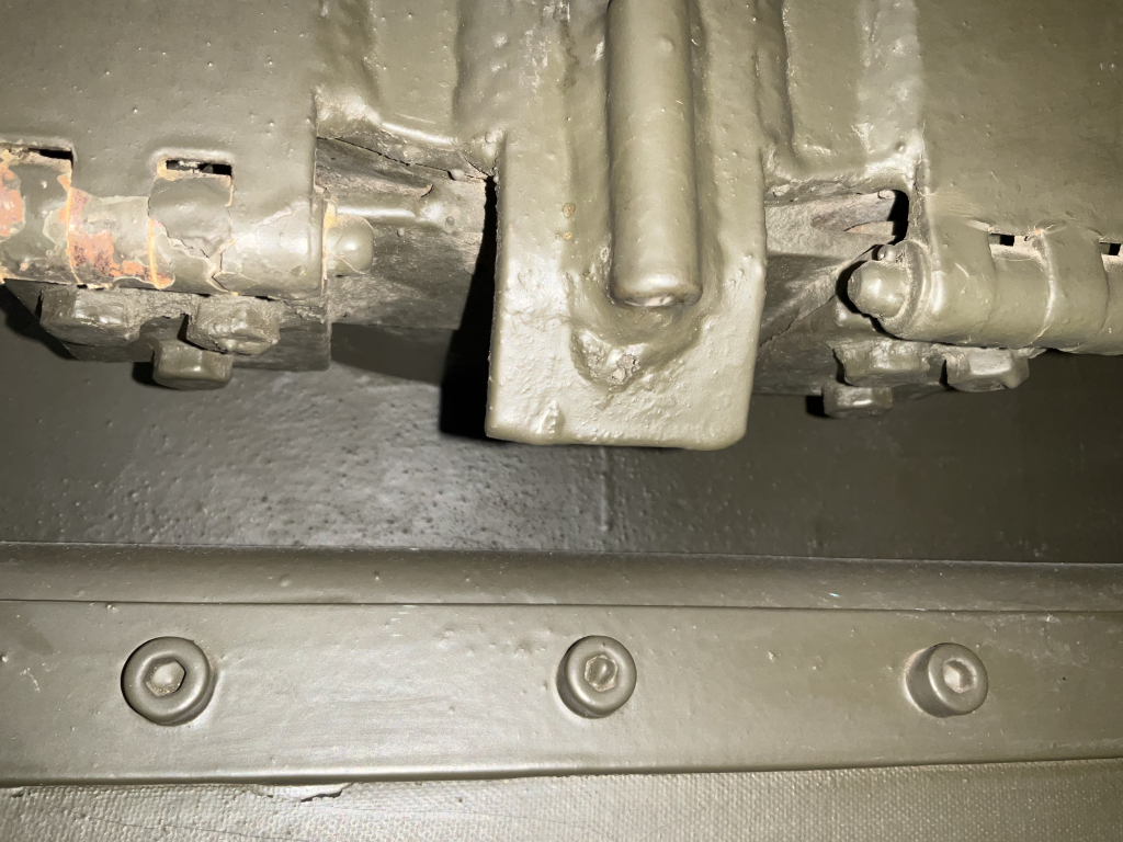
Note the weld beading and the missing detail inside each end of the bolted on housing on the upper side - the kit just has the housing fit on the flat upper hull.
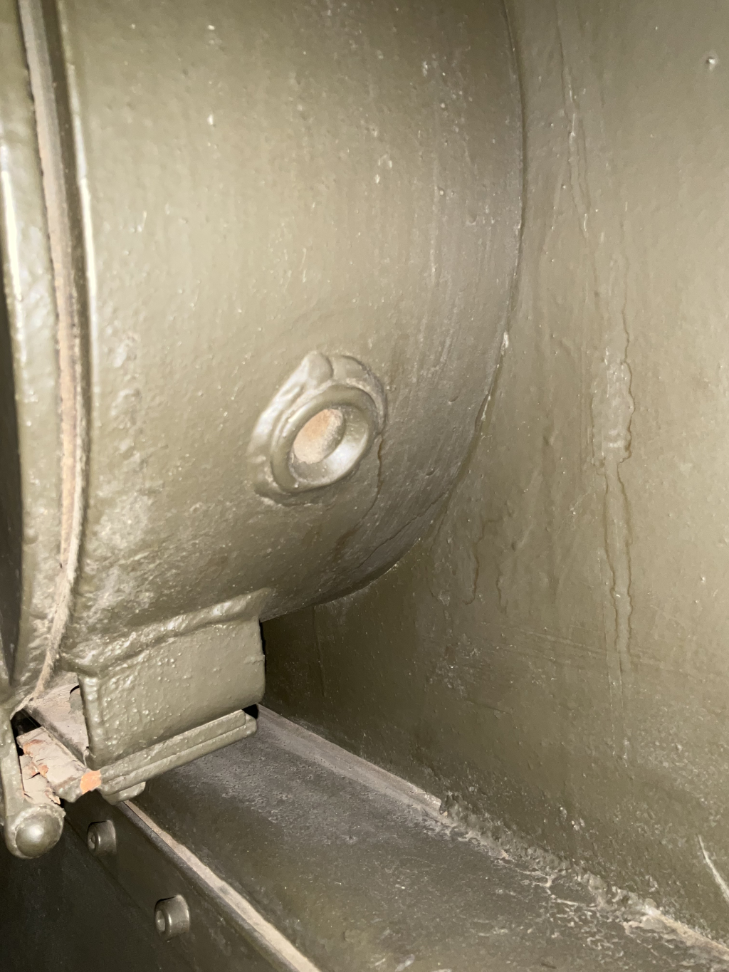
Note the rectangular hole here. The area below this is actually recessed a little, but you really can’t see it much on the model, so I lived with the way it was and just drilled/cut out the hole:
and a reference for when you come to the assembly of the headlights - the instruactions are not that clear and the horn mount needs a strip of brass or styrene to add to the etch bit that attaches to the cage bar:
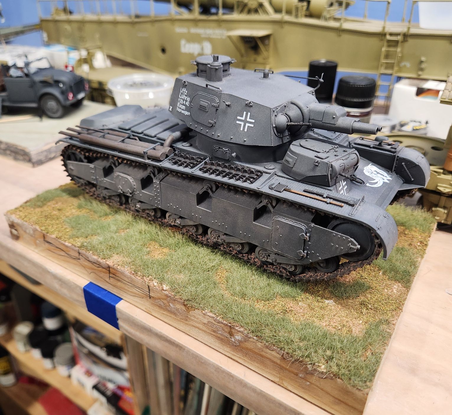
Some touching up here and there to get it all blended in. Edges need cleaning and painting. Hopefully all will be done by the end of next weekend; just coming off spring break and we are having a community day on Wednesday so I have to interact with parents and “represent”. Then I turn a year older on Thursday so won’t get any work done then either.