BMW 507 Coupe and Cabrio Dual Build - Revell 1/24 kits

Intro and Background

The gloriously handsome BMW 507 Coupé was initially the brainchild of an American, the car importer Max Hoffman who, in 1954, persuaded the BMW management to produce a roadster version of the BMW 501 and BMW 502 saloons. His idea was to plug the contemporary gap between the expensive German Mercedes-Benz 300SL and the cheap and relatively under-powered British Triumph and MG sports cars.

BMW engineer Fritz Fiedler – of pre-war BMW 328 fame - was assigned to design the rolling chassis, using existing components wherever possible. Early body designs by Veritas-BMW performance-car specialist, Ernst Loof, were rejected by Hoffman, who found them unattractive. In November 1954, largely at Hoffman’s insistence, BMW contracted industrial designer Albrecht von Goertz to style both the BMW 503 and the top-end 507.

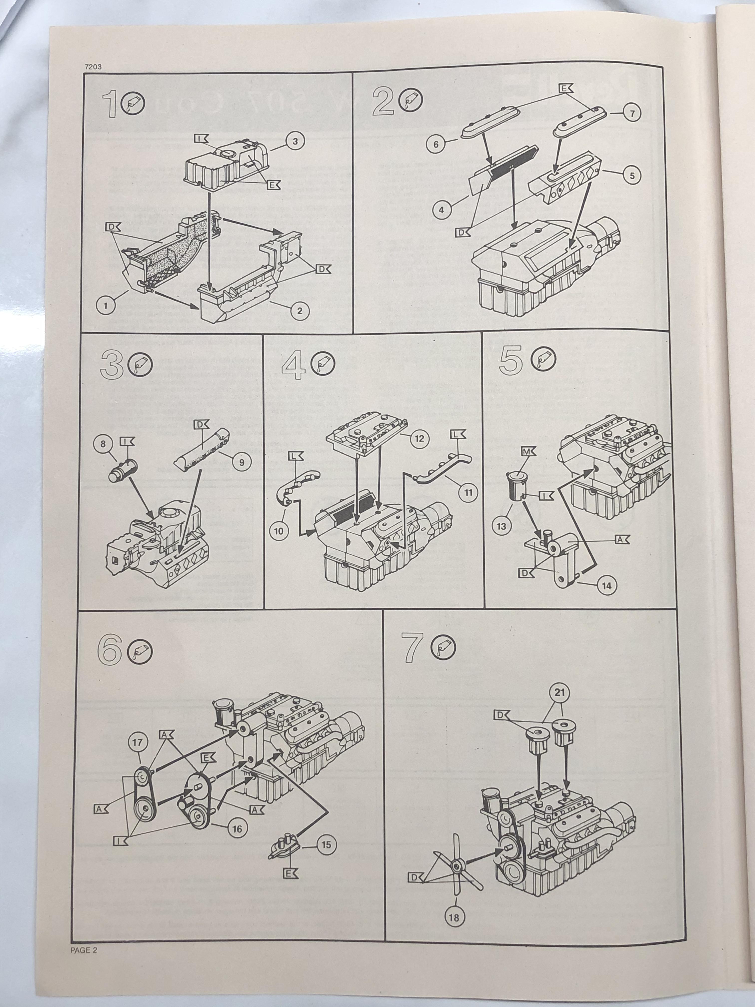
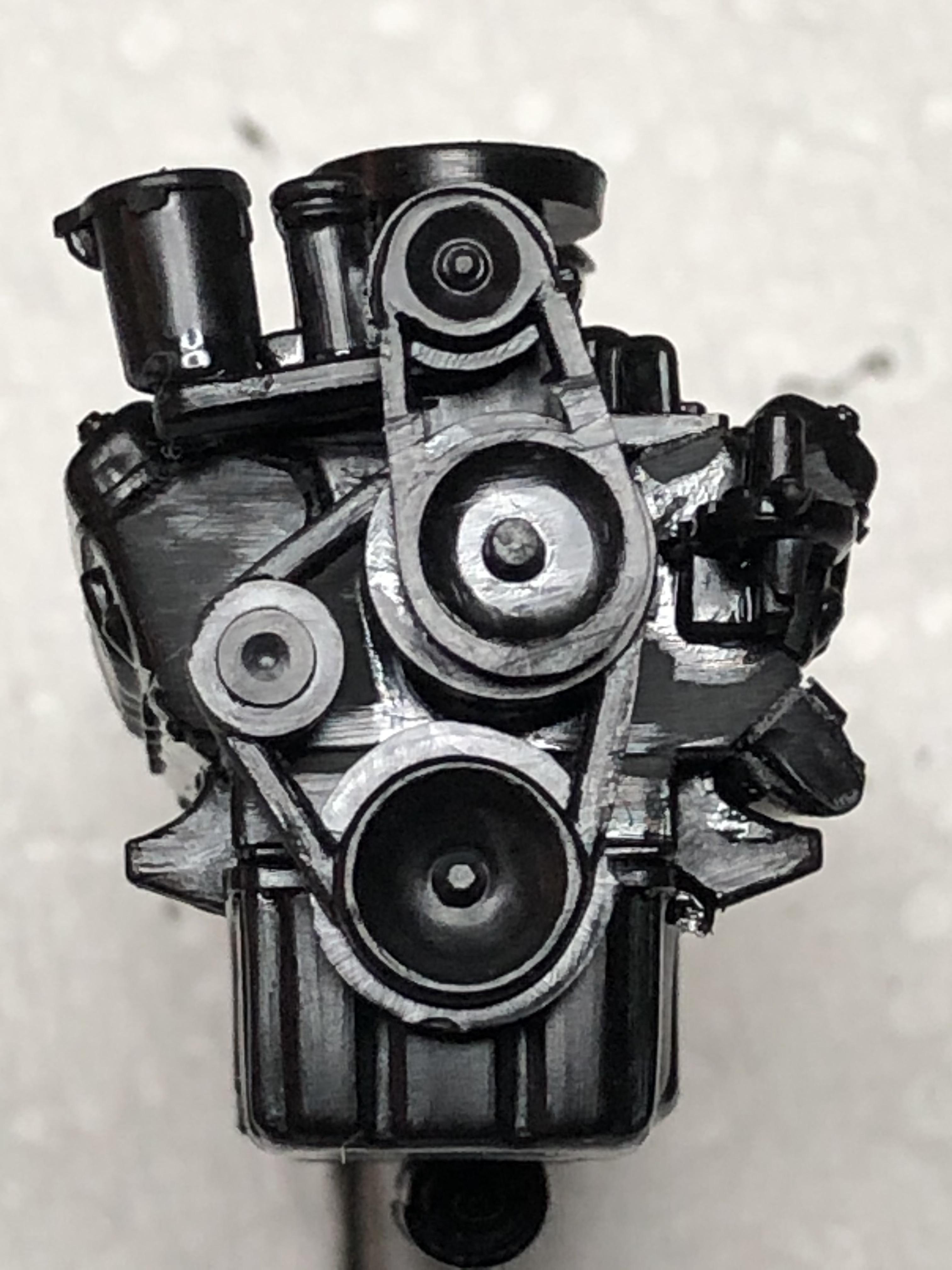
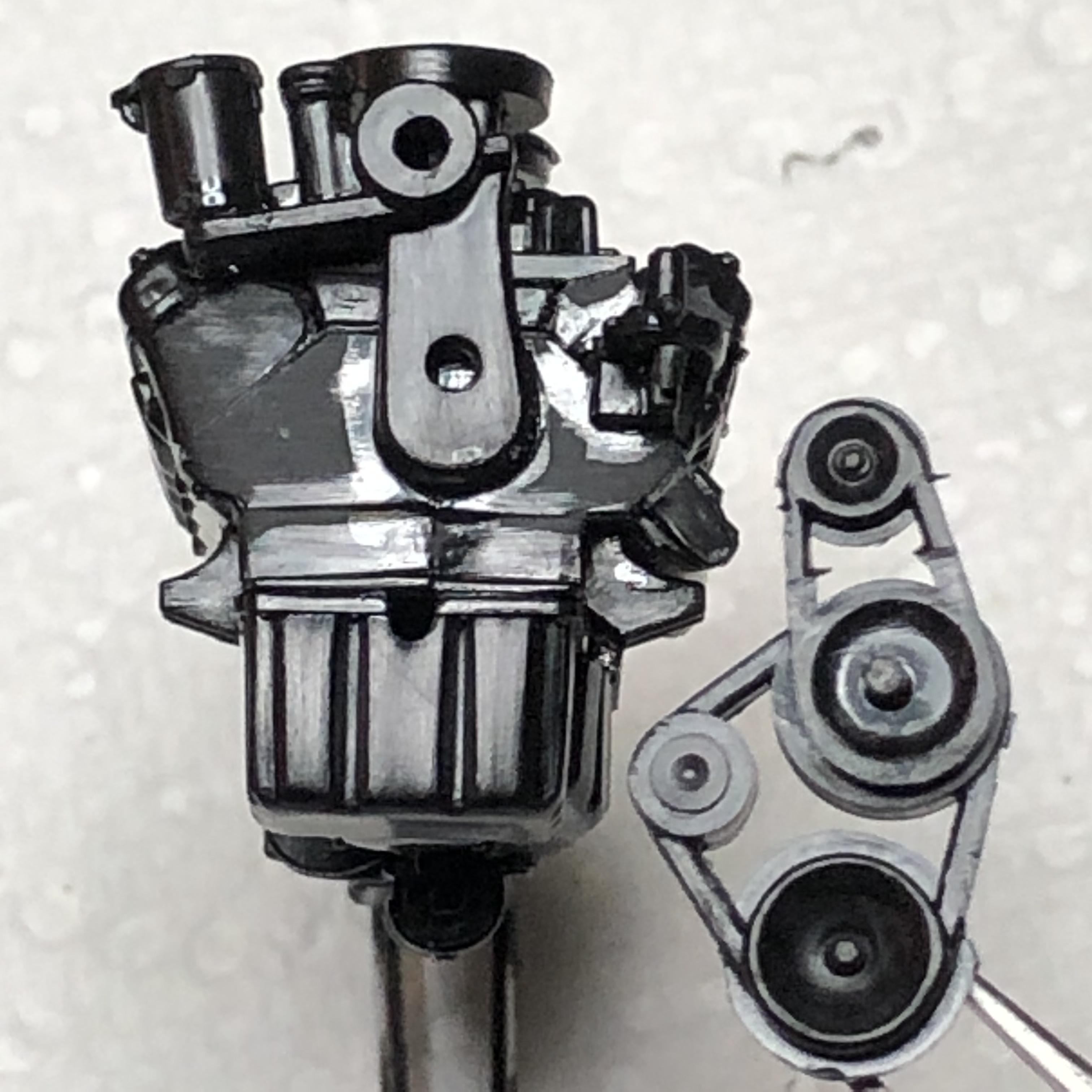
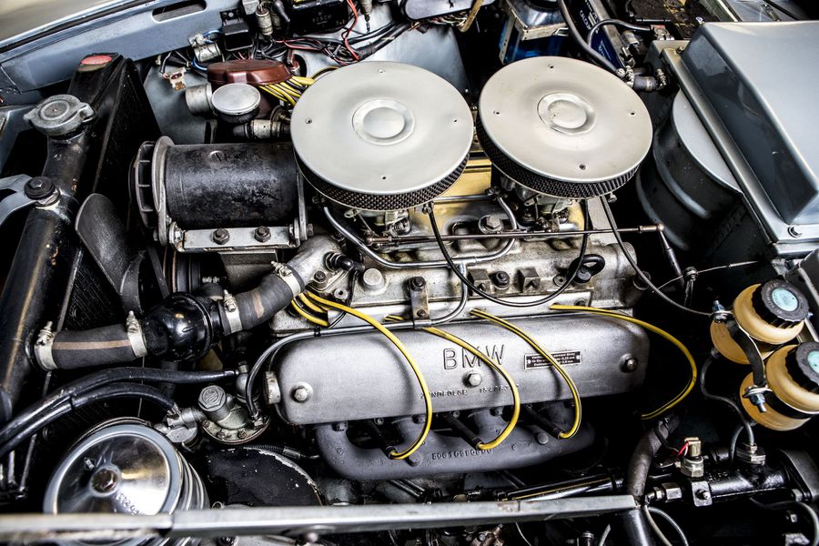
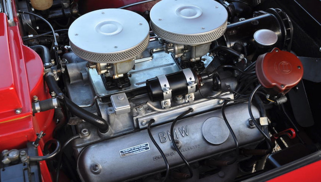
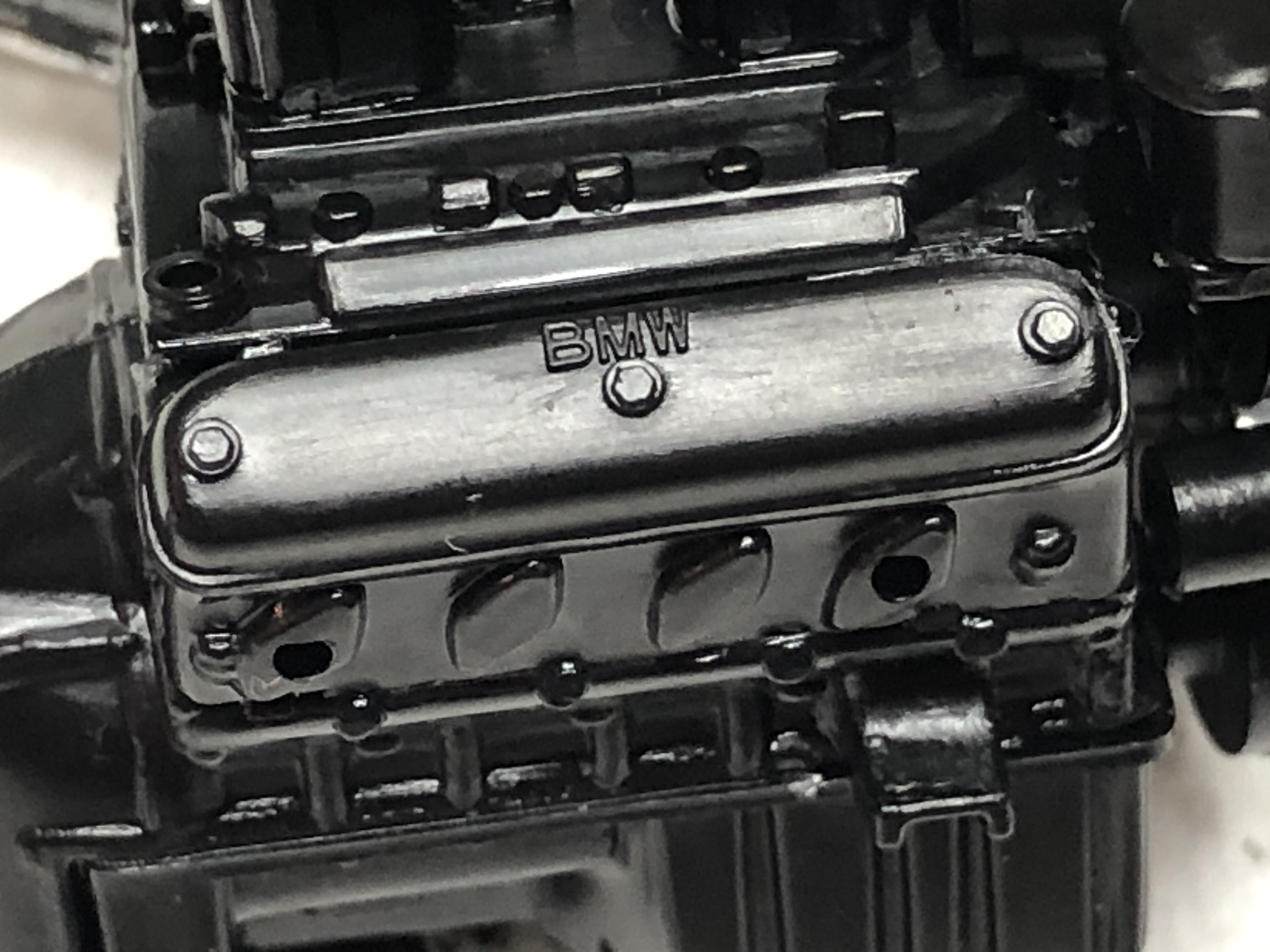
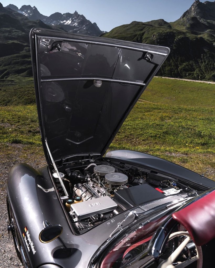
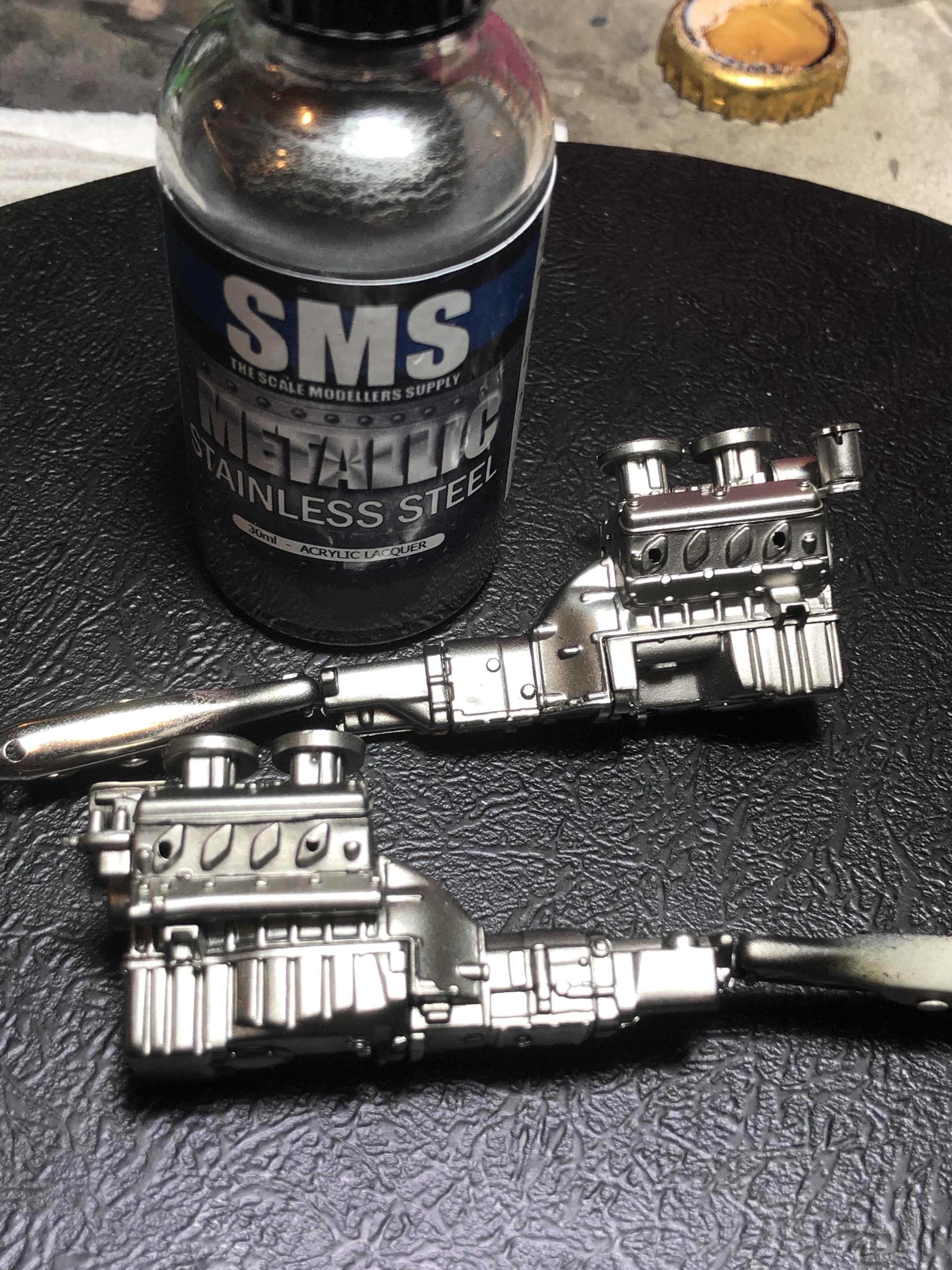
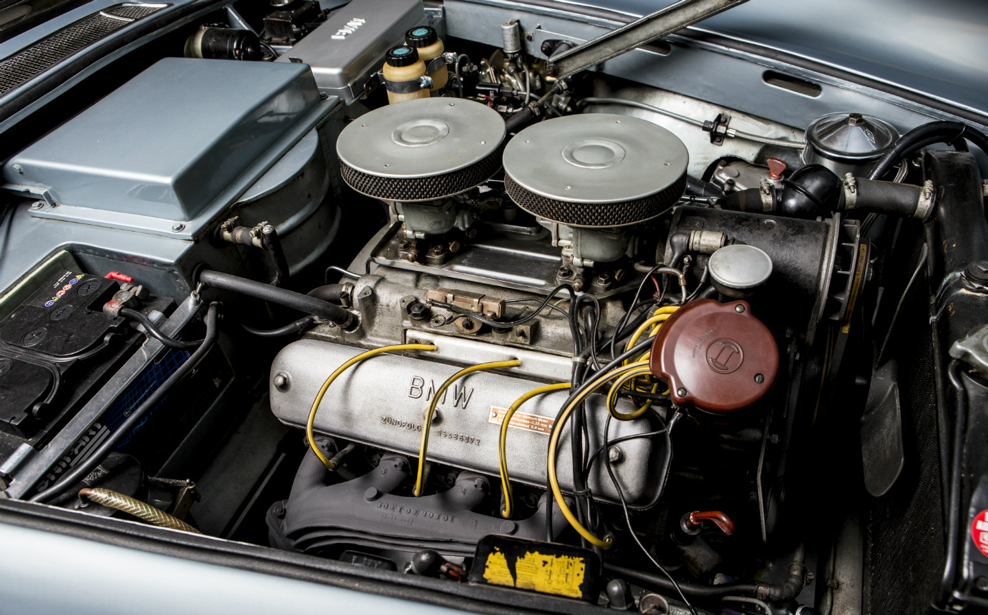
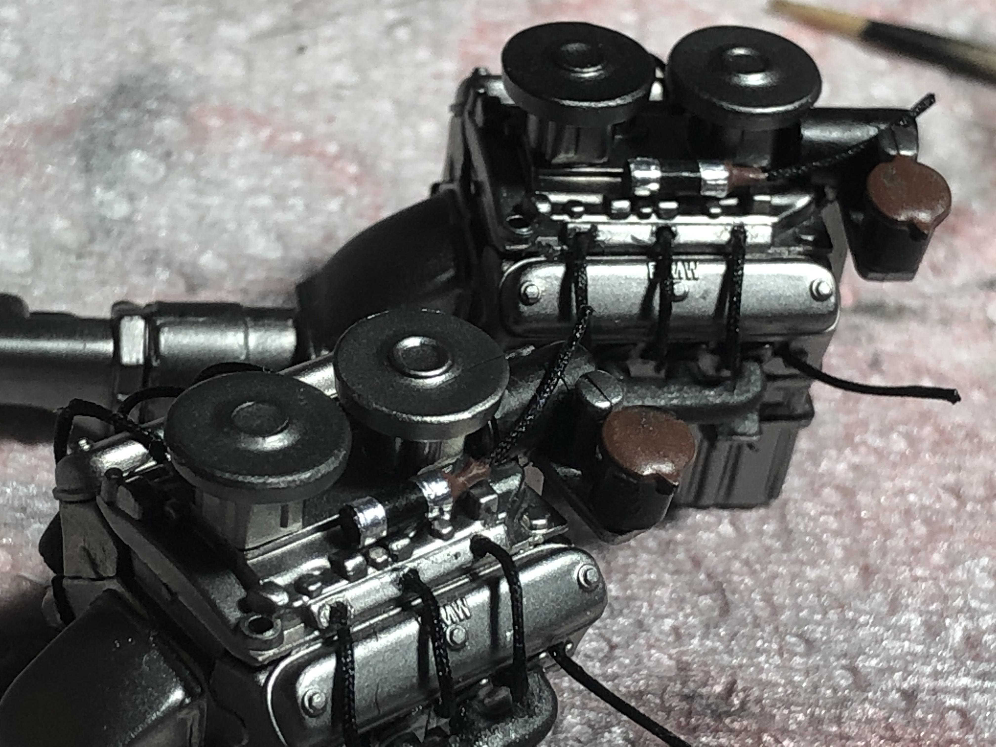
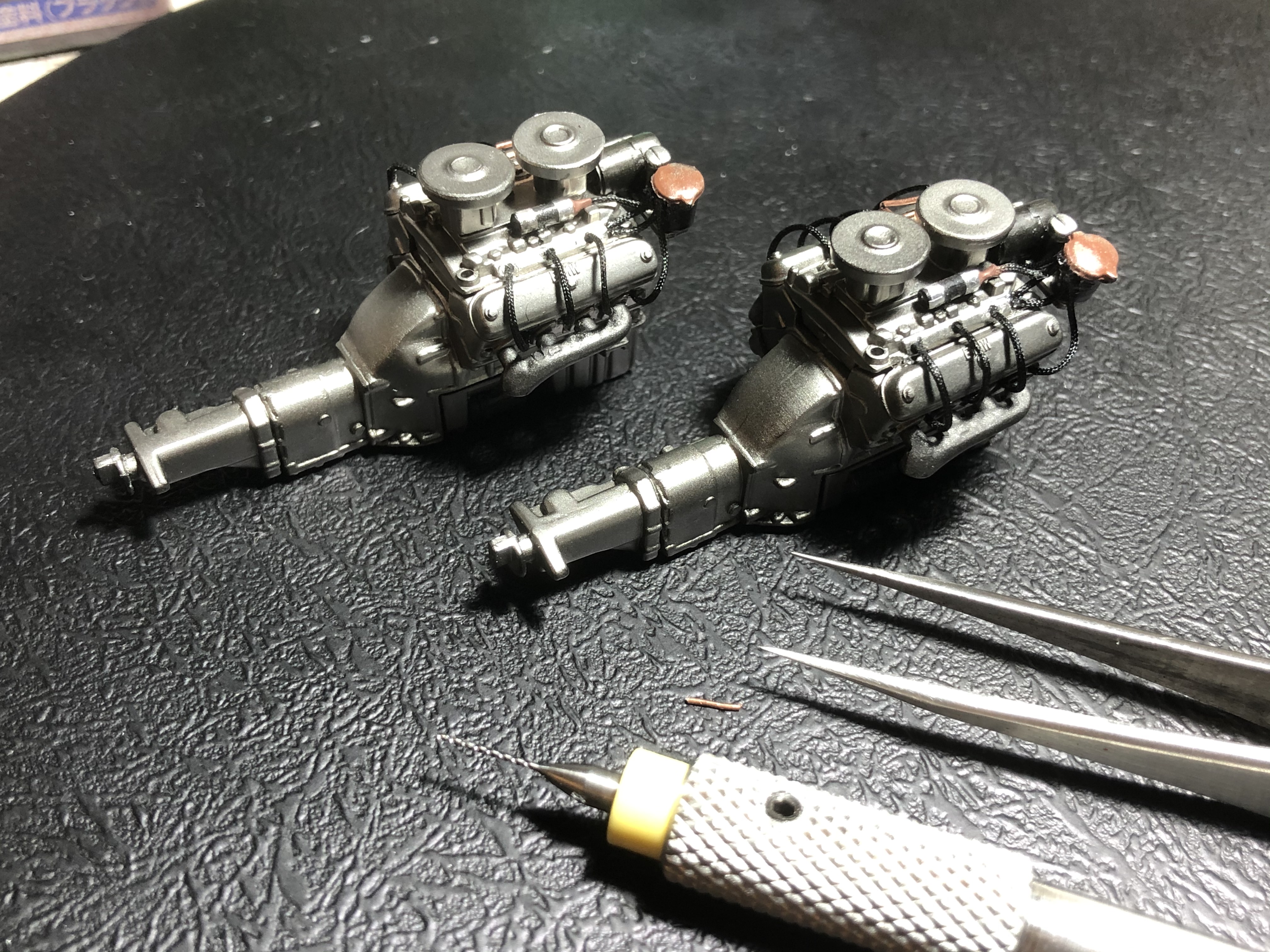
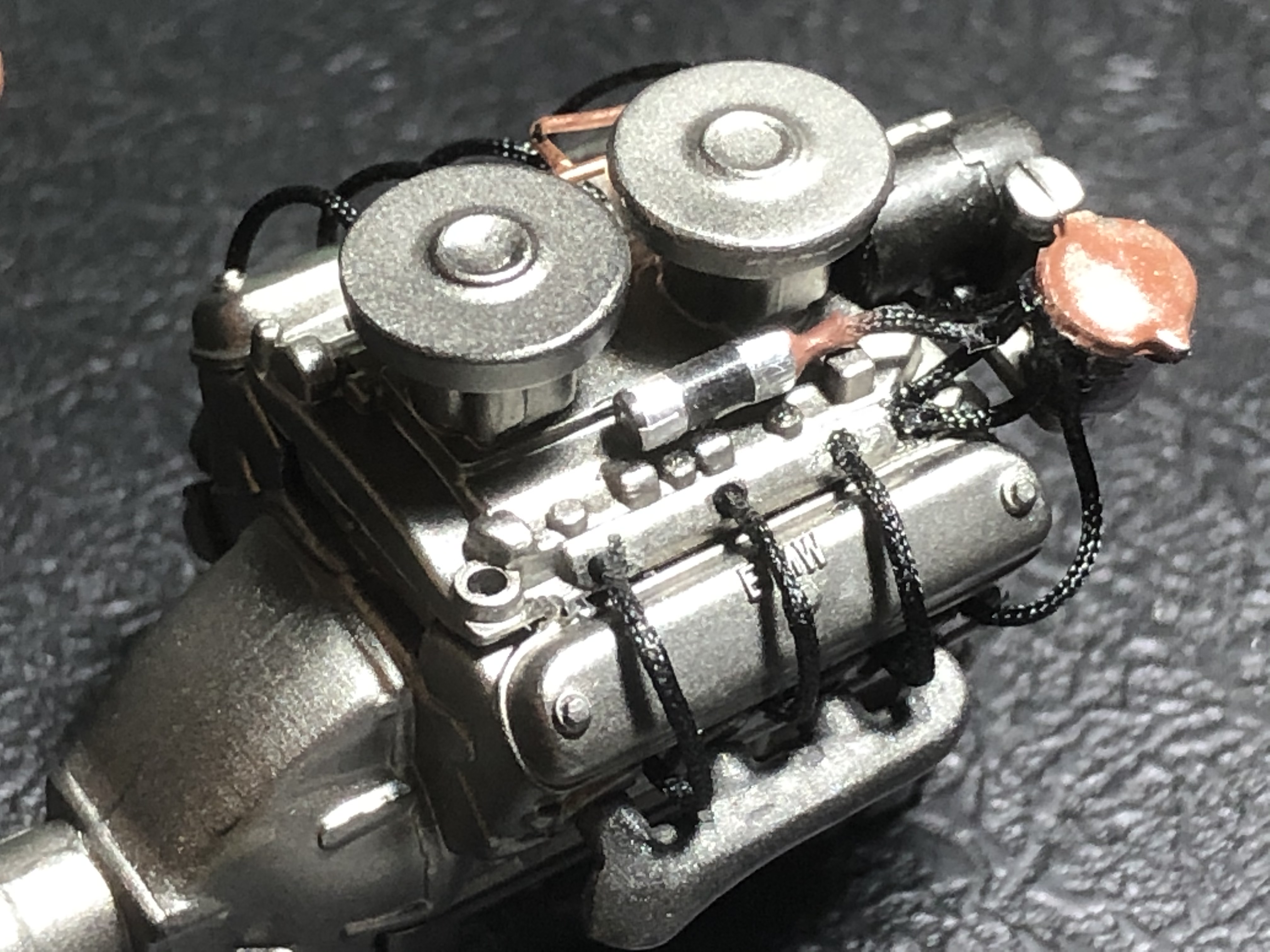
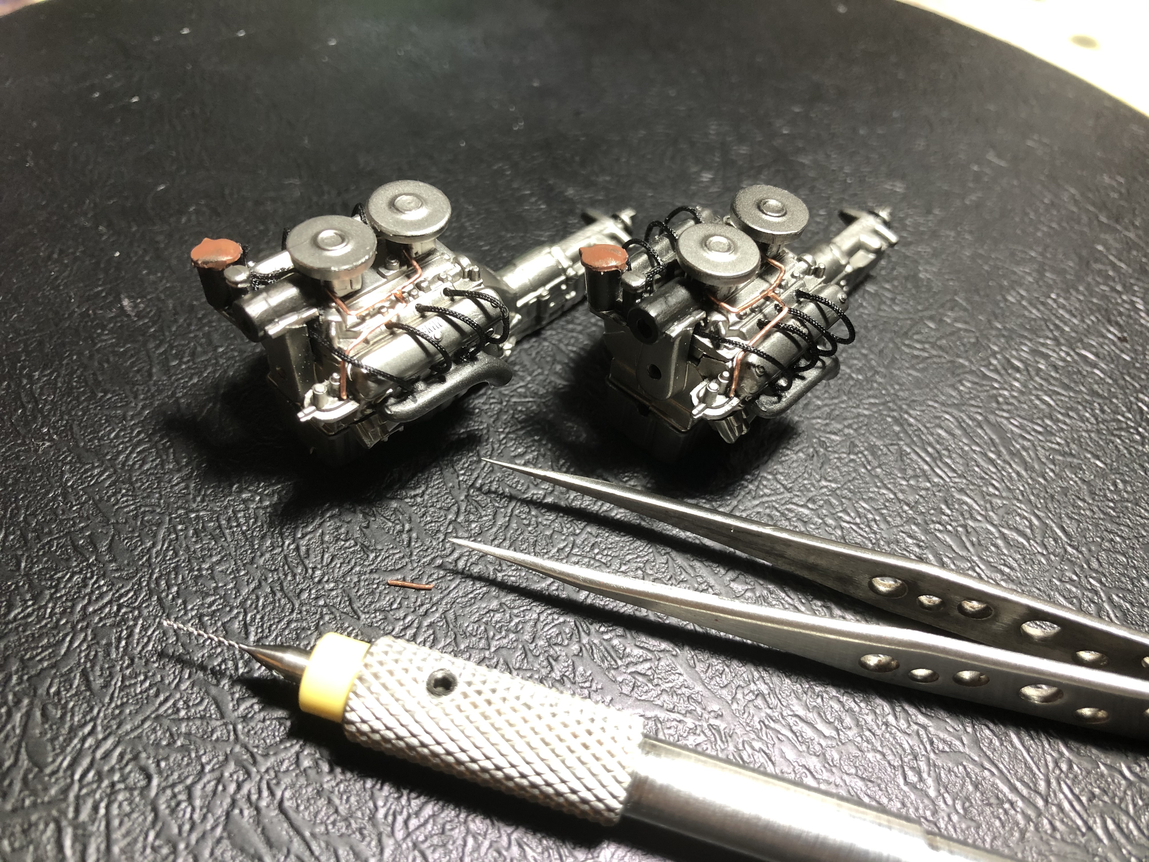
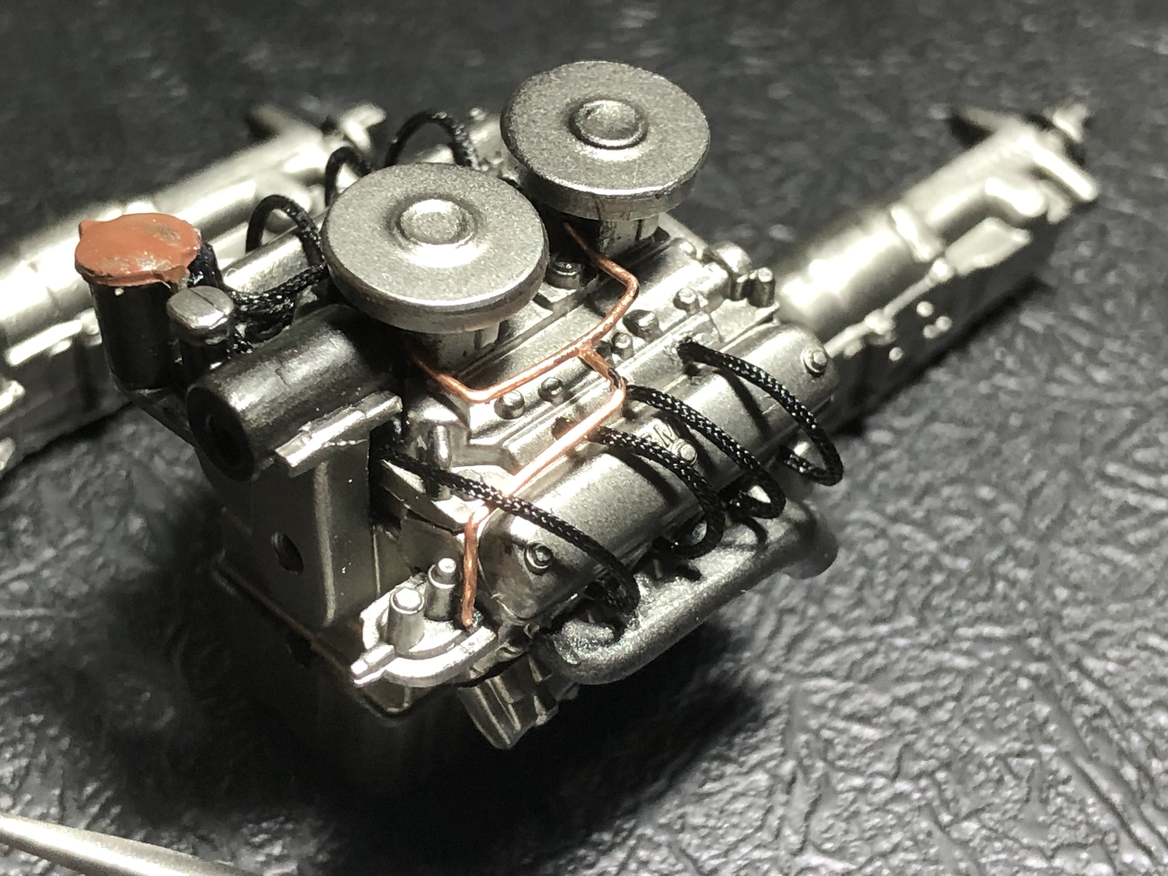
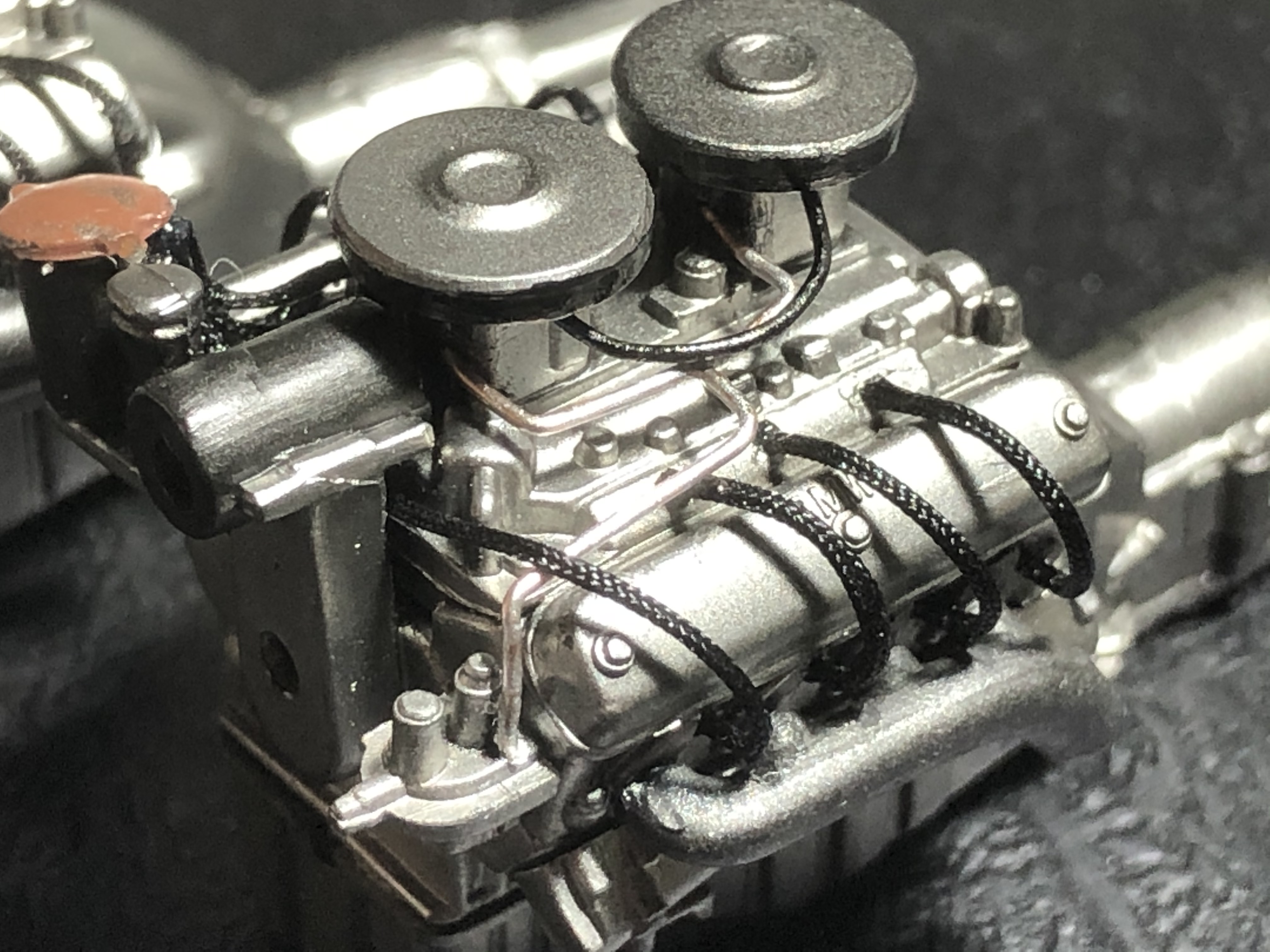
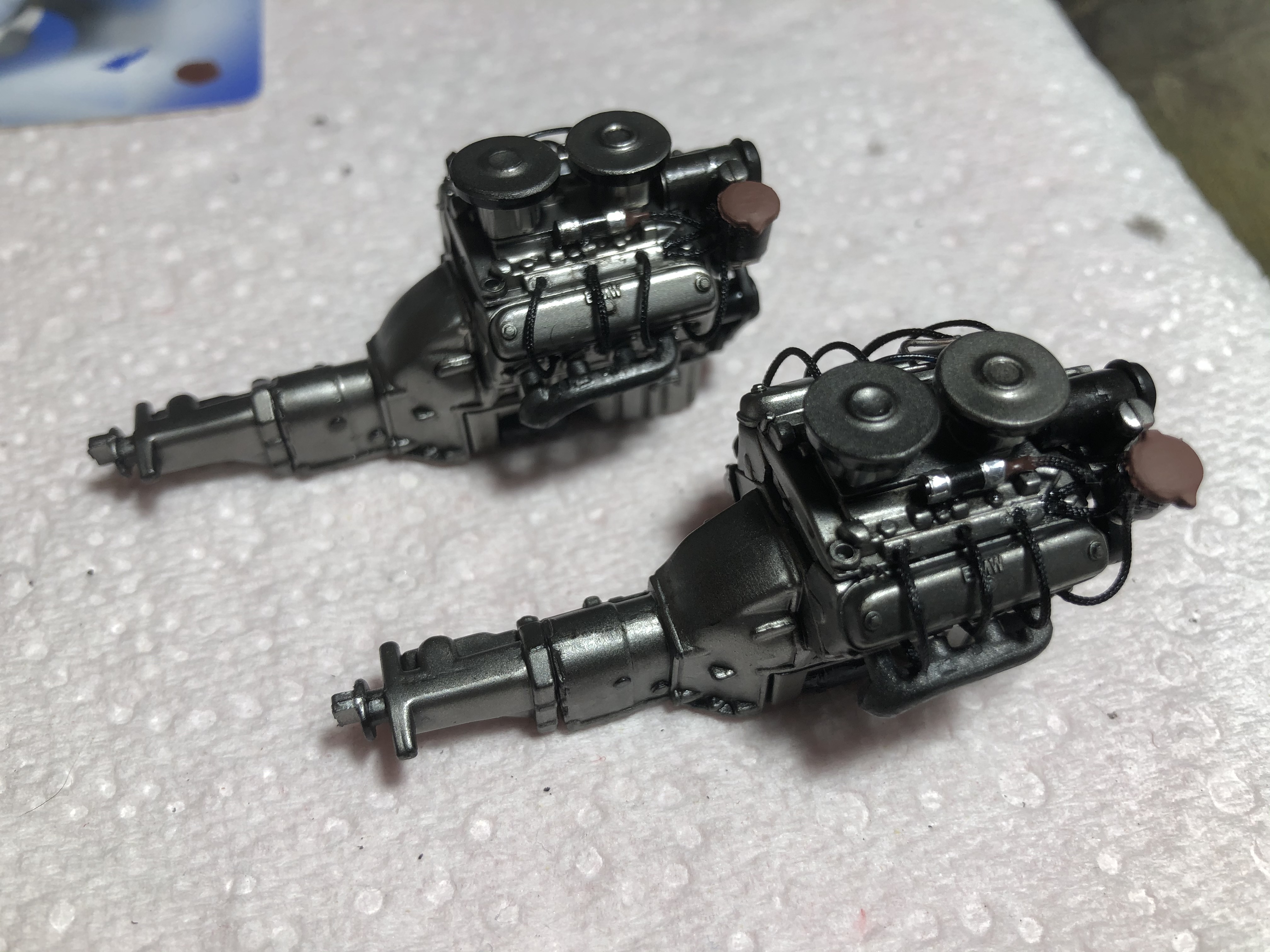
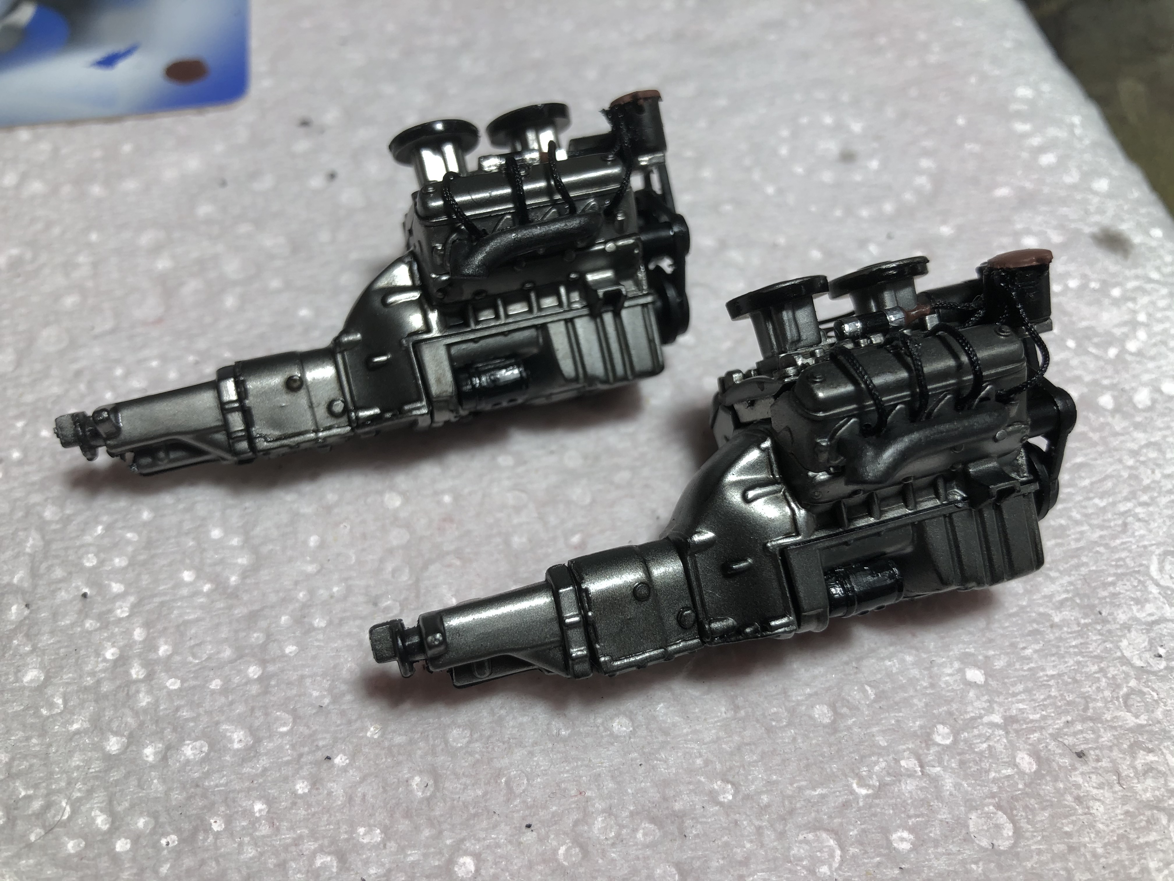
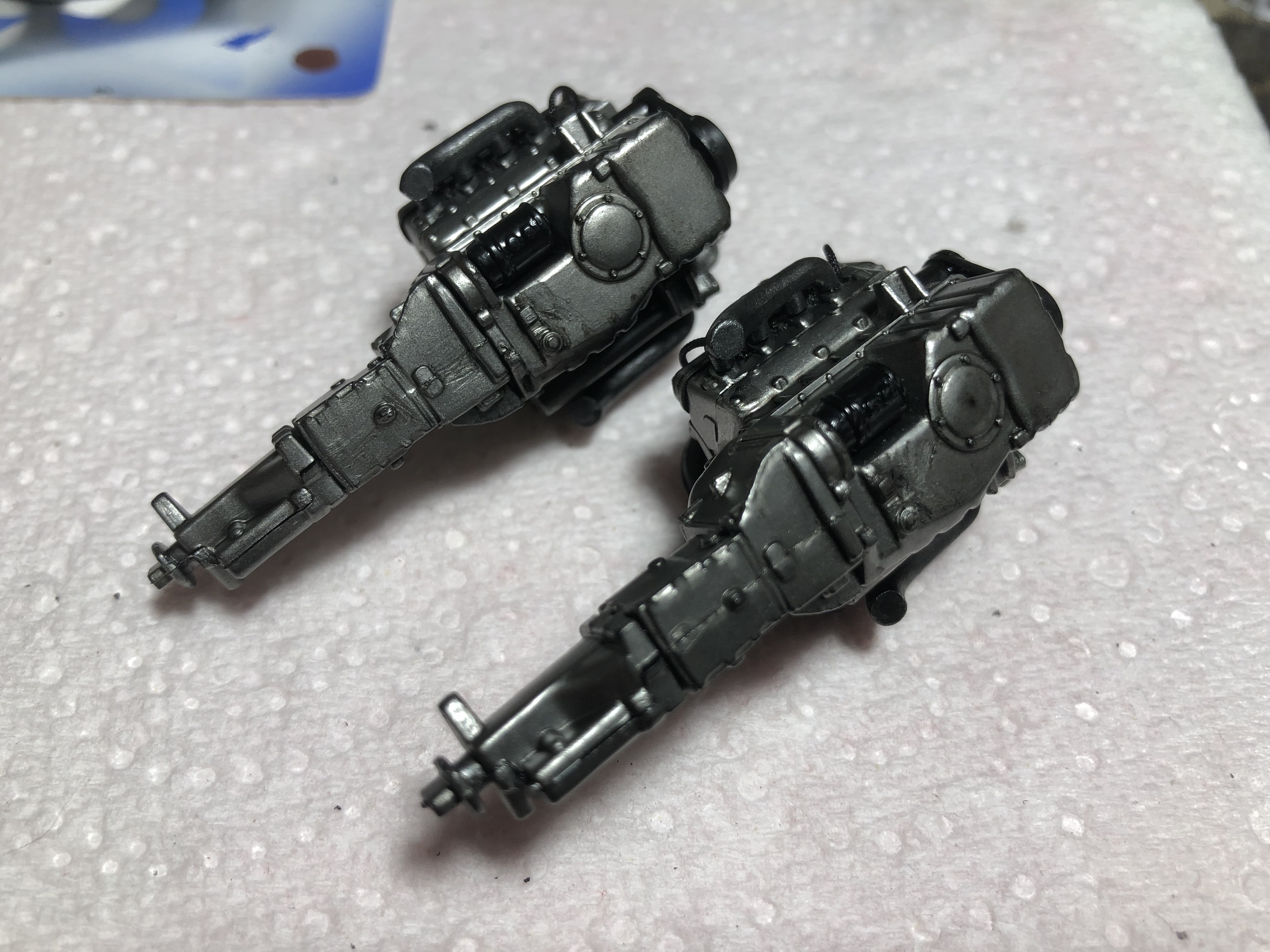
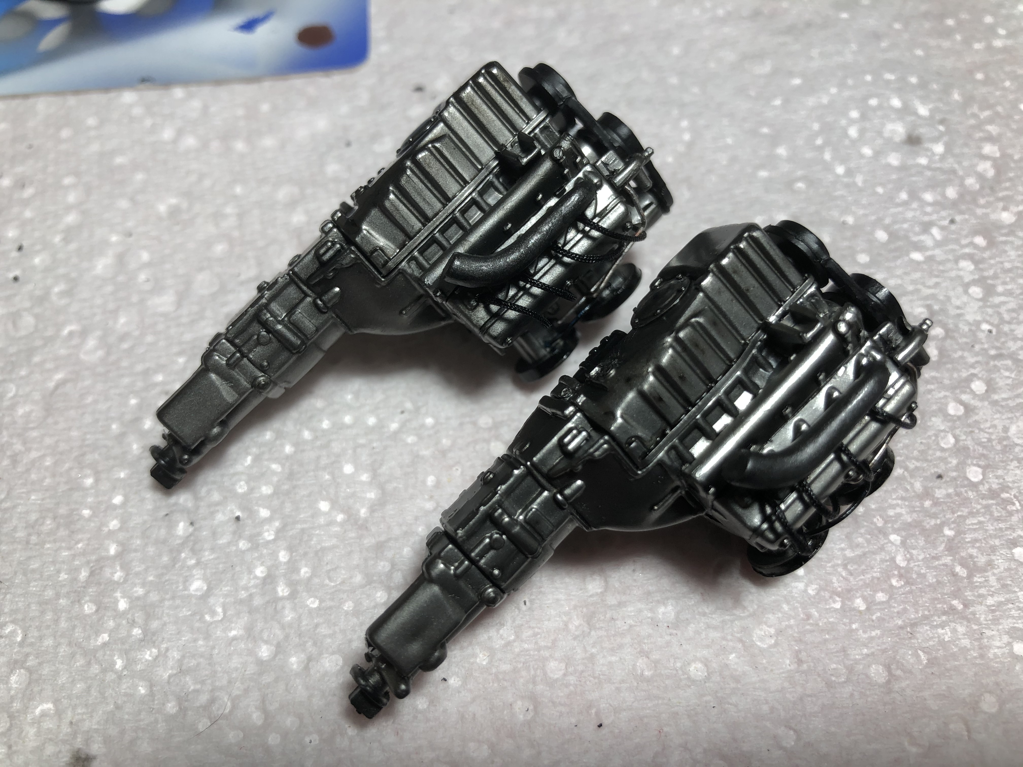
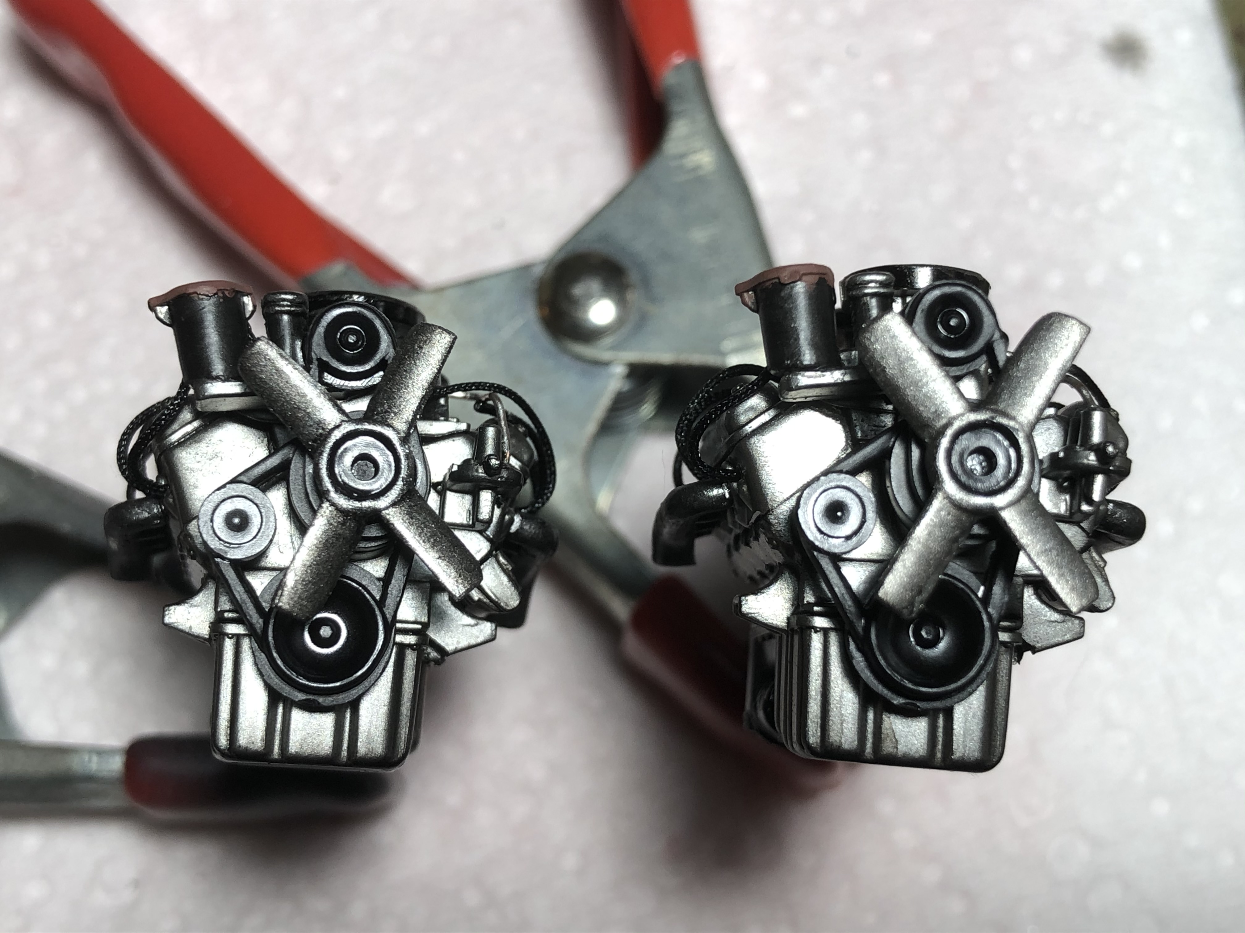
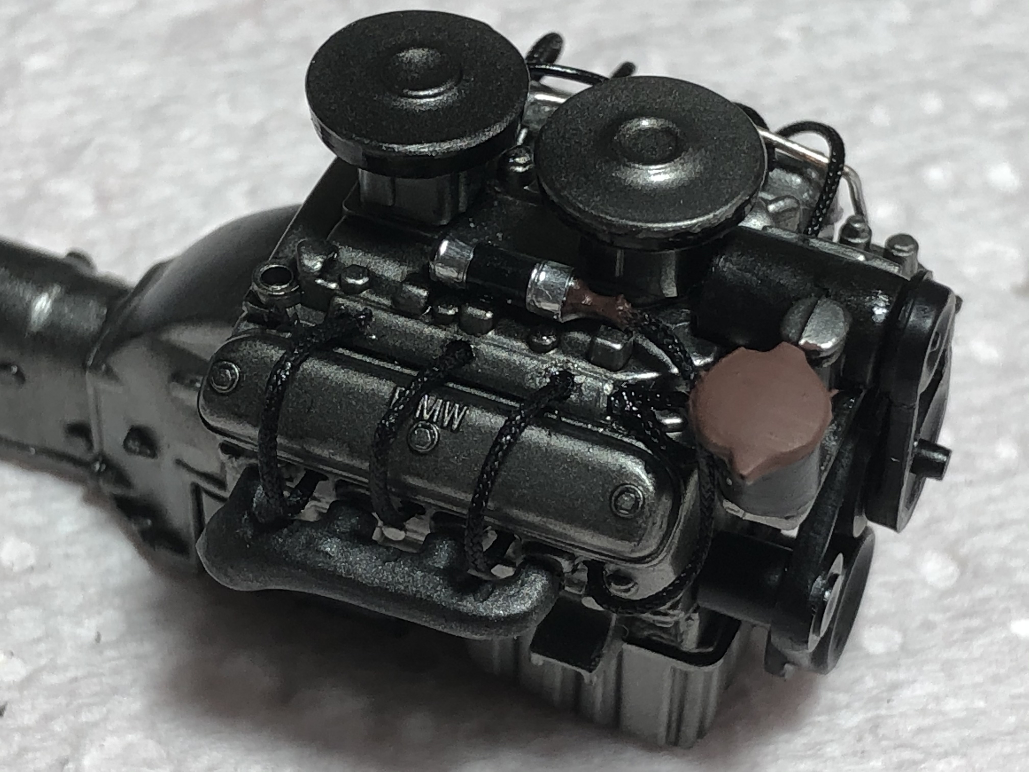
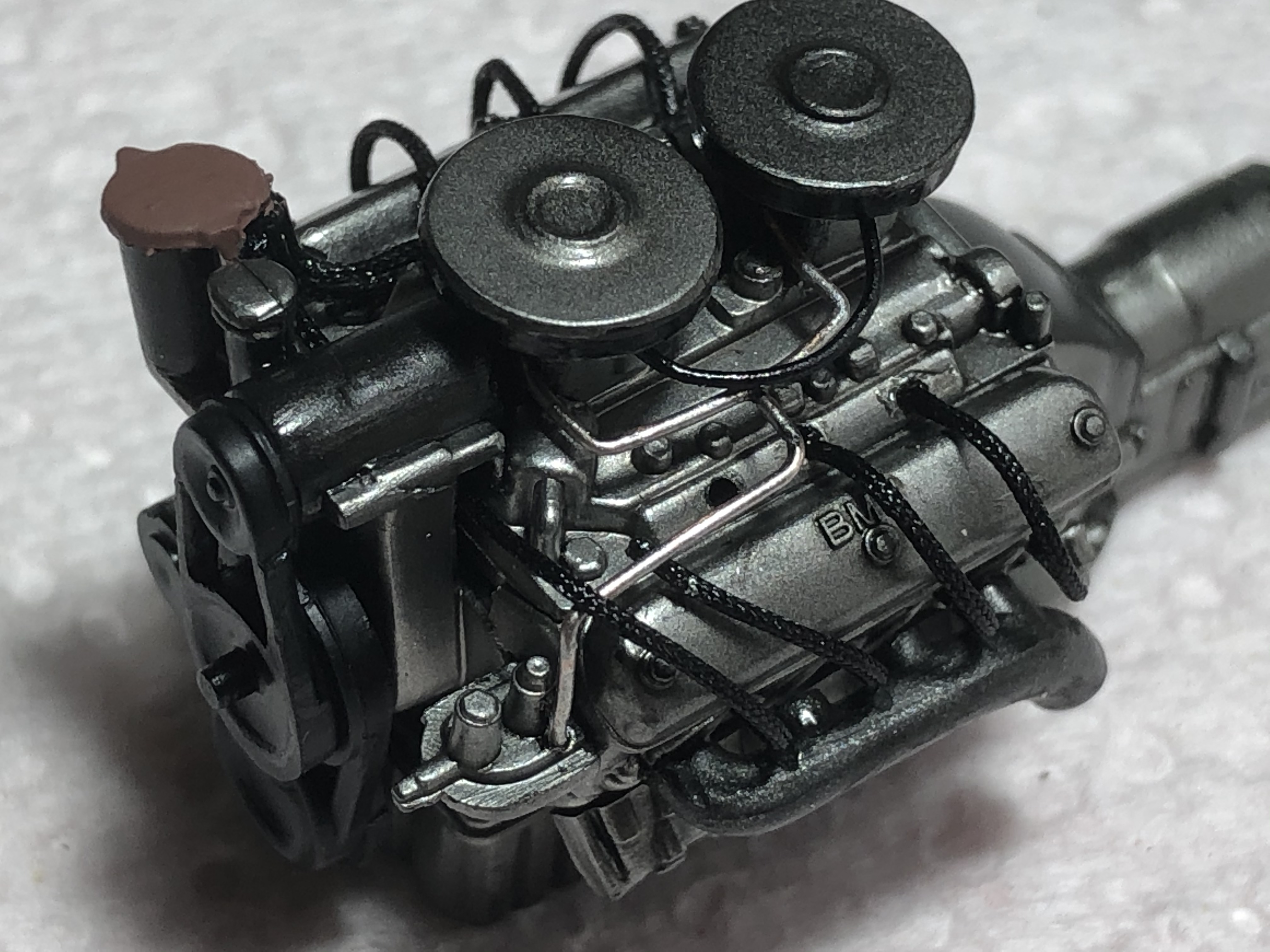
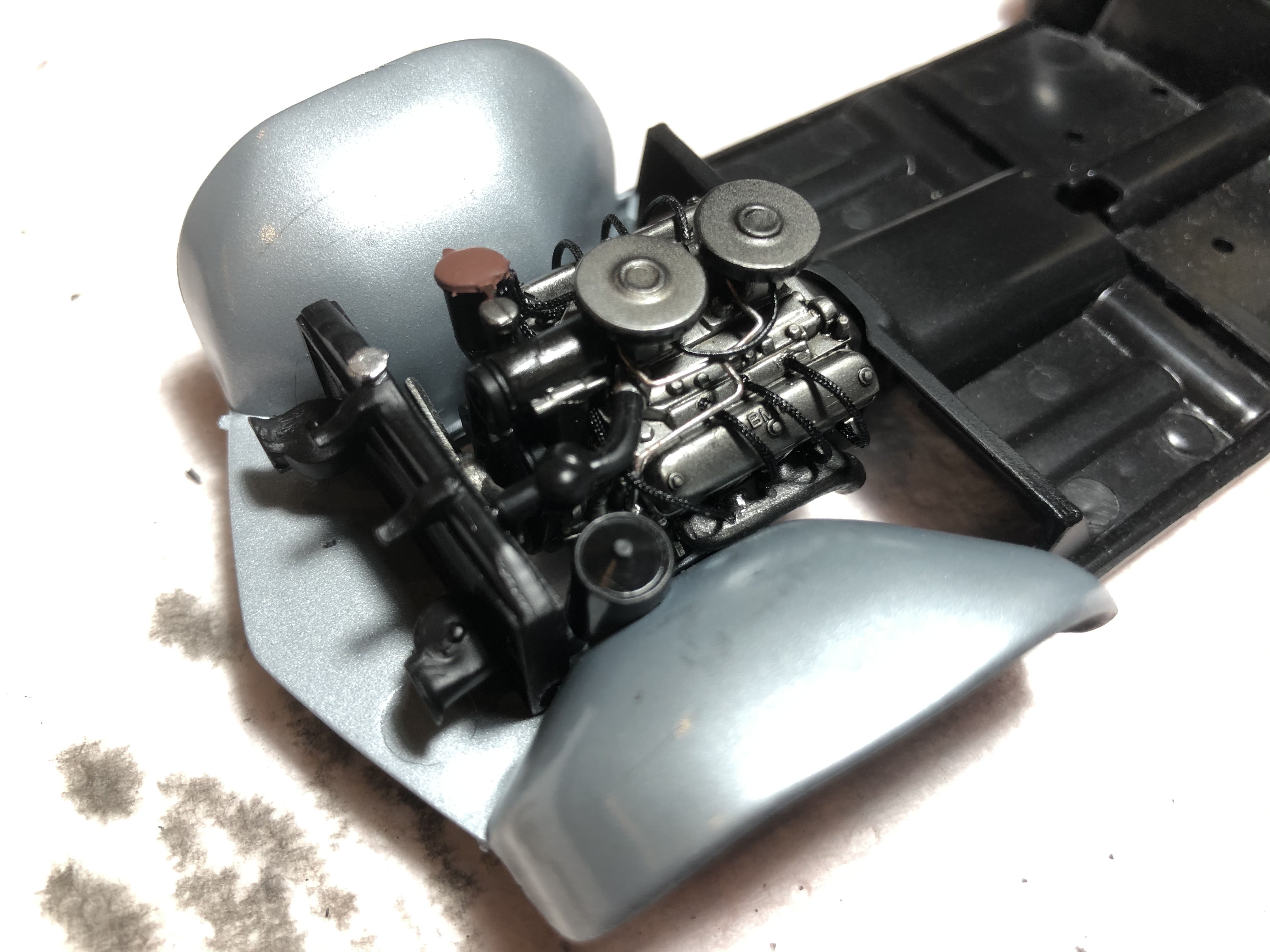
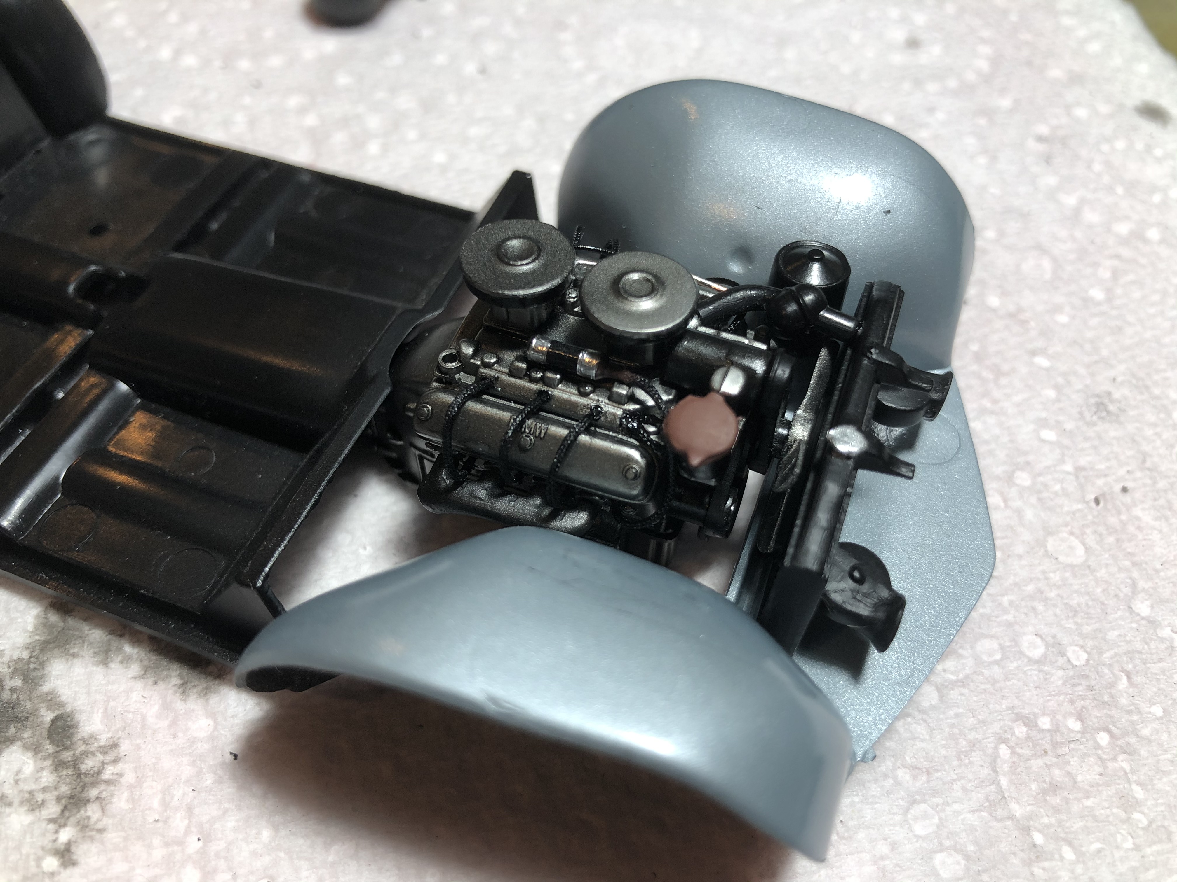
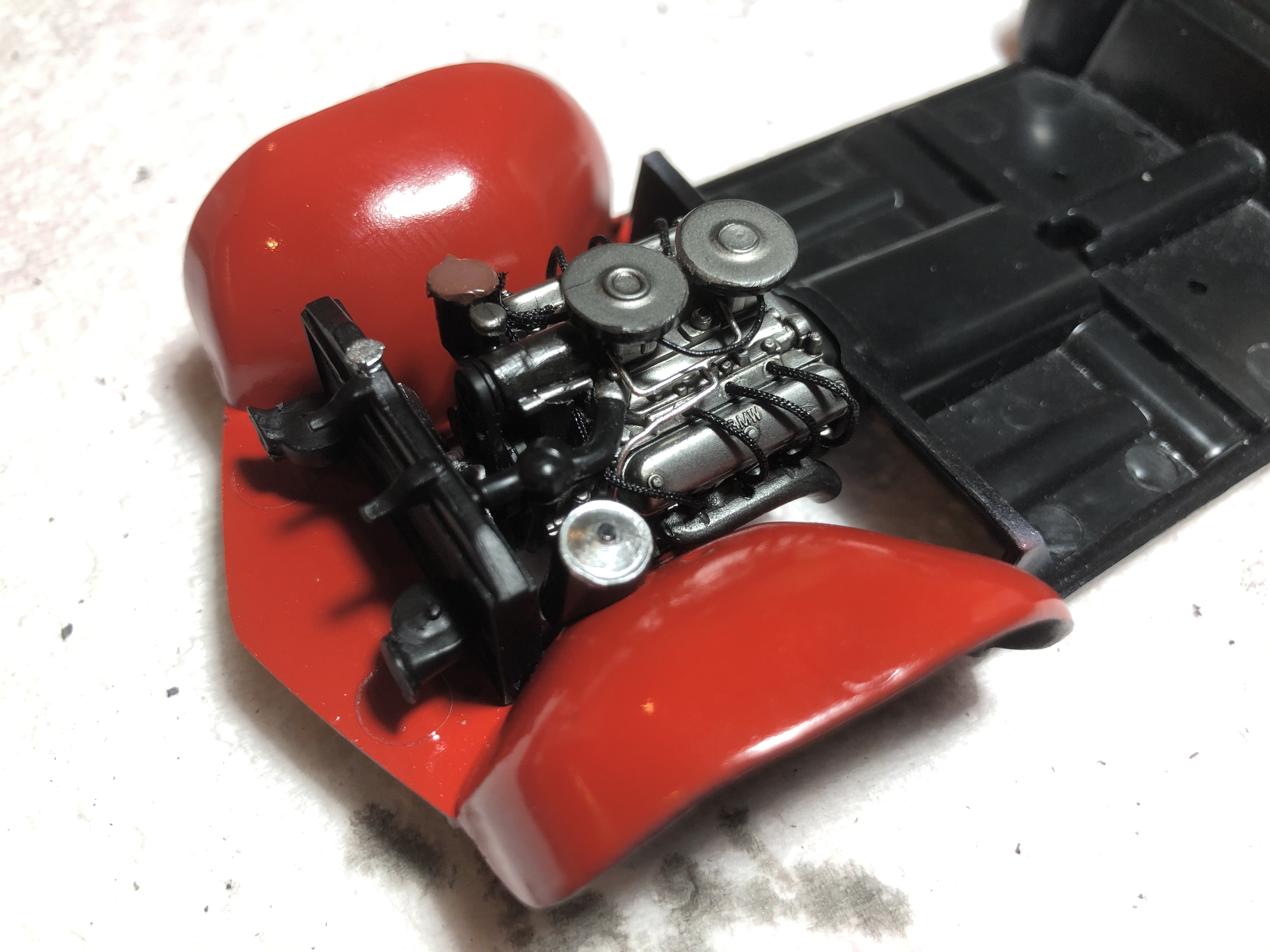
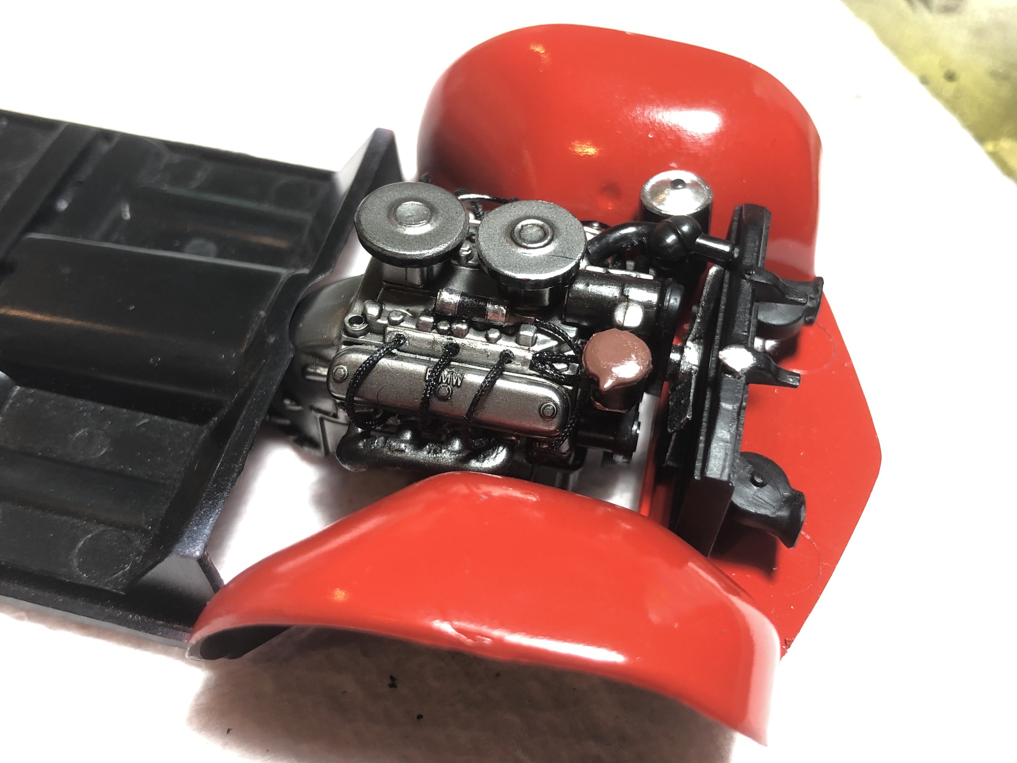
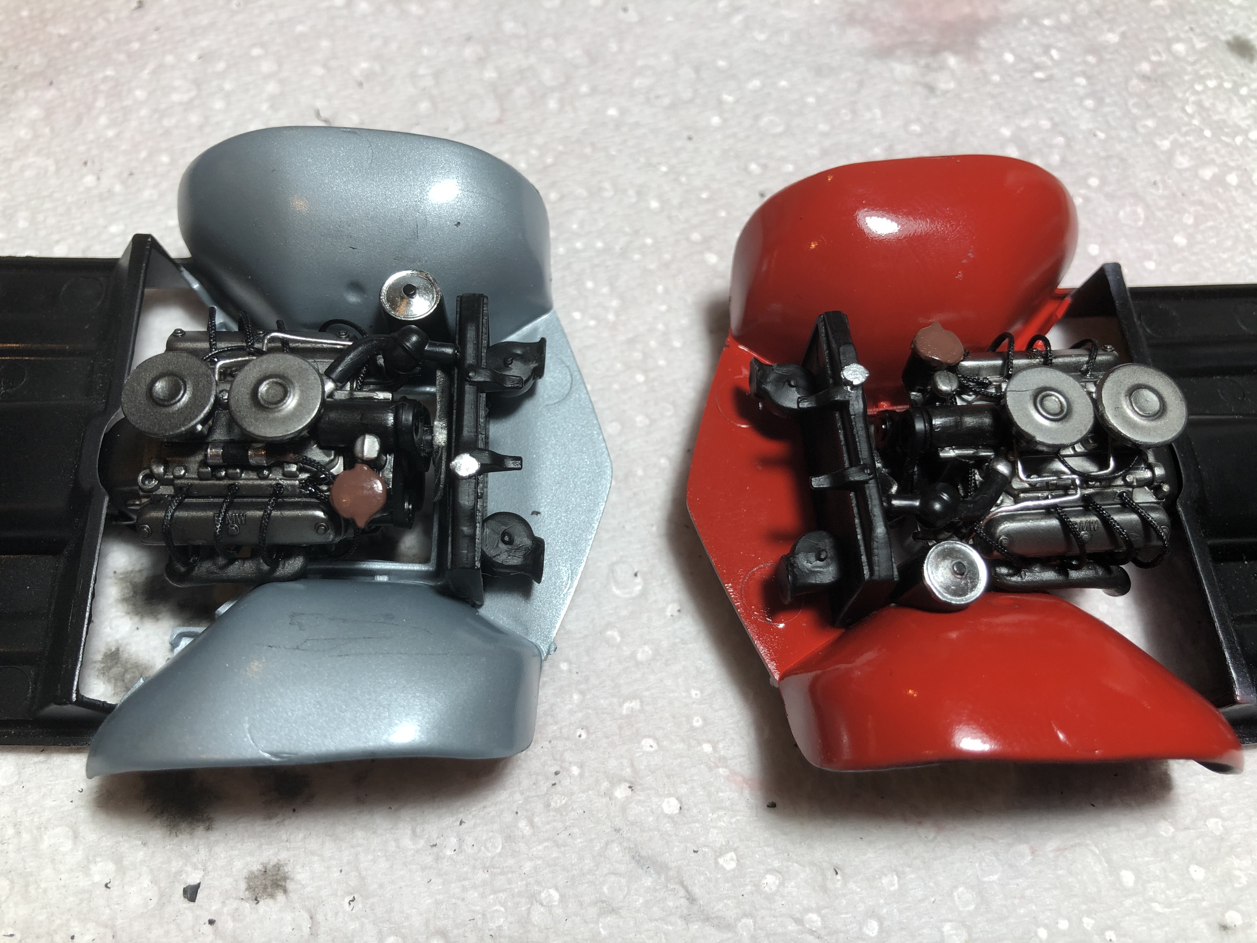
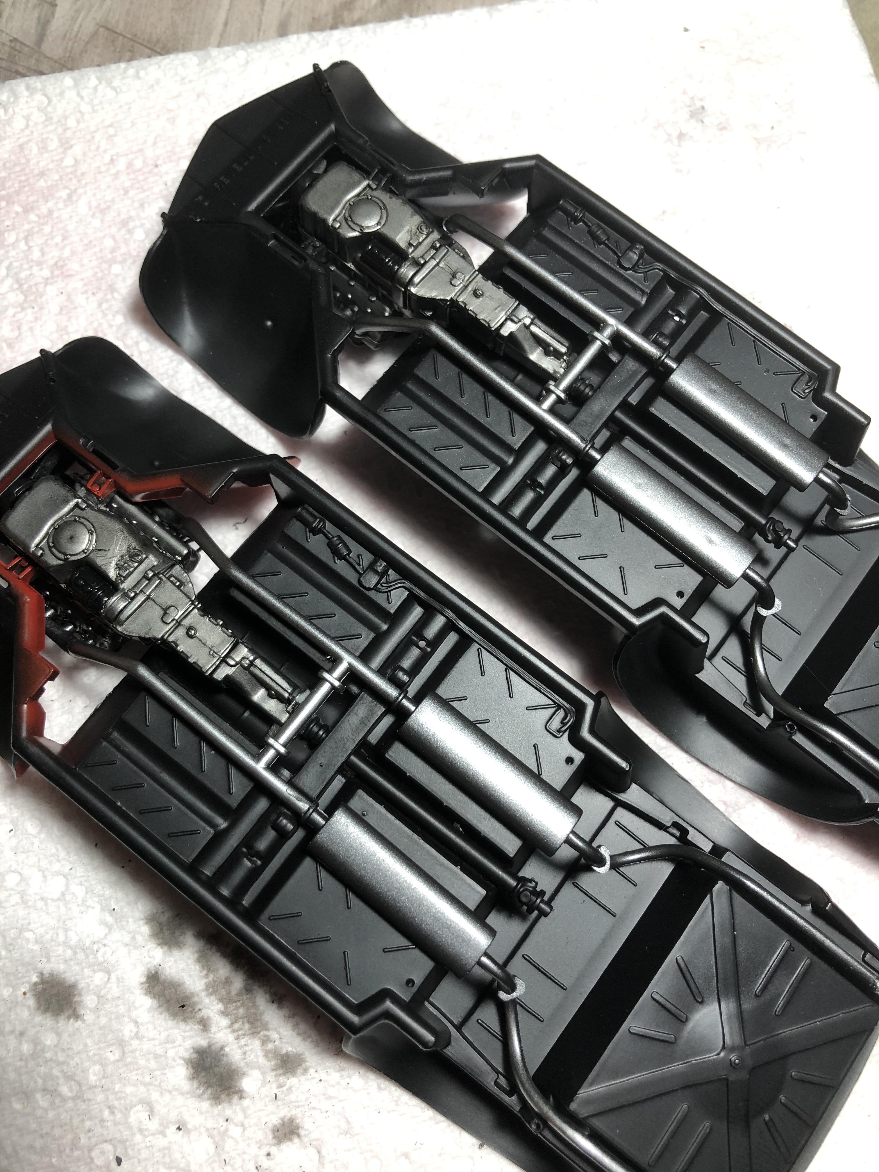
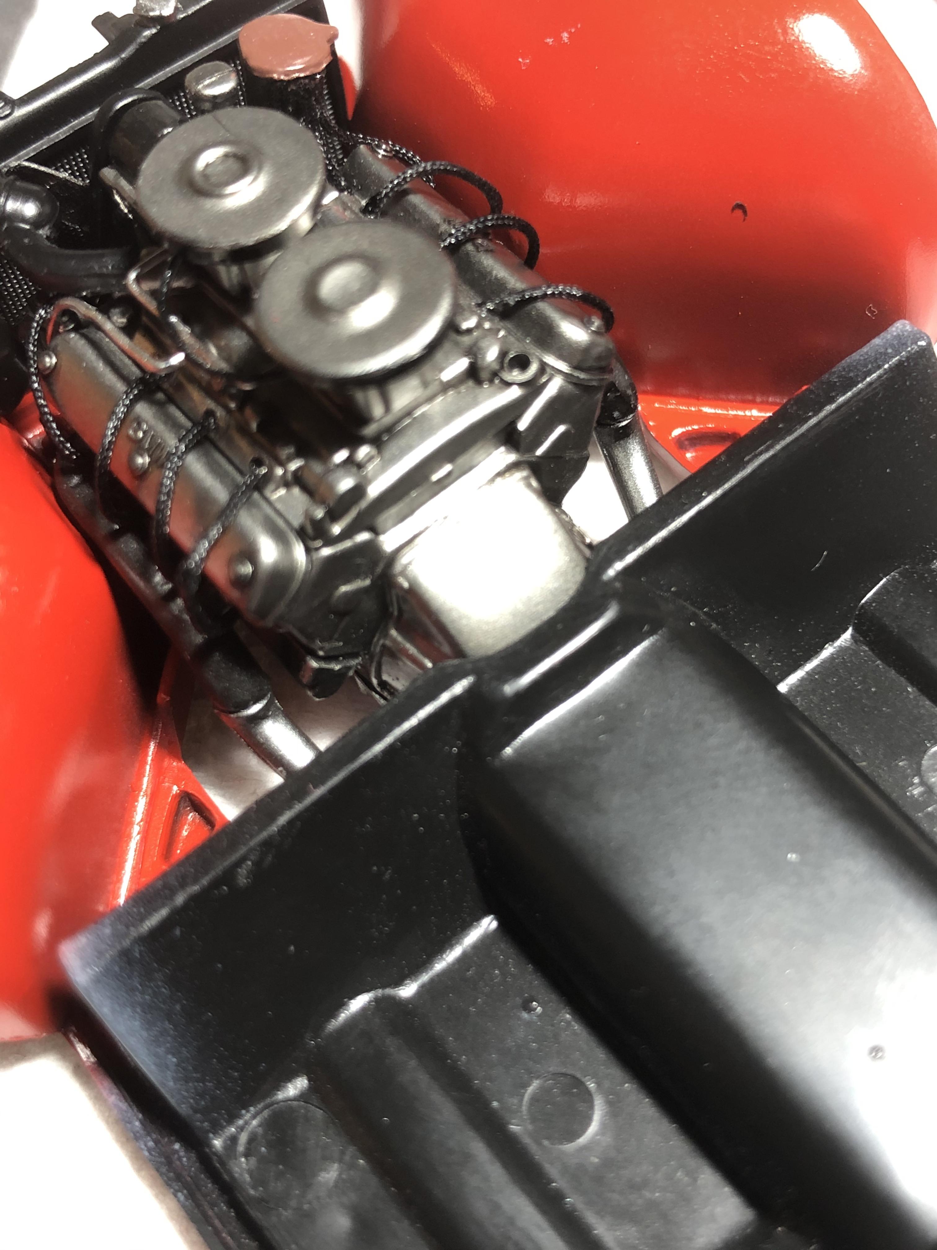
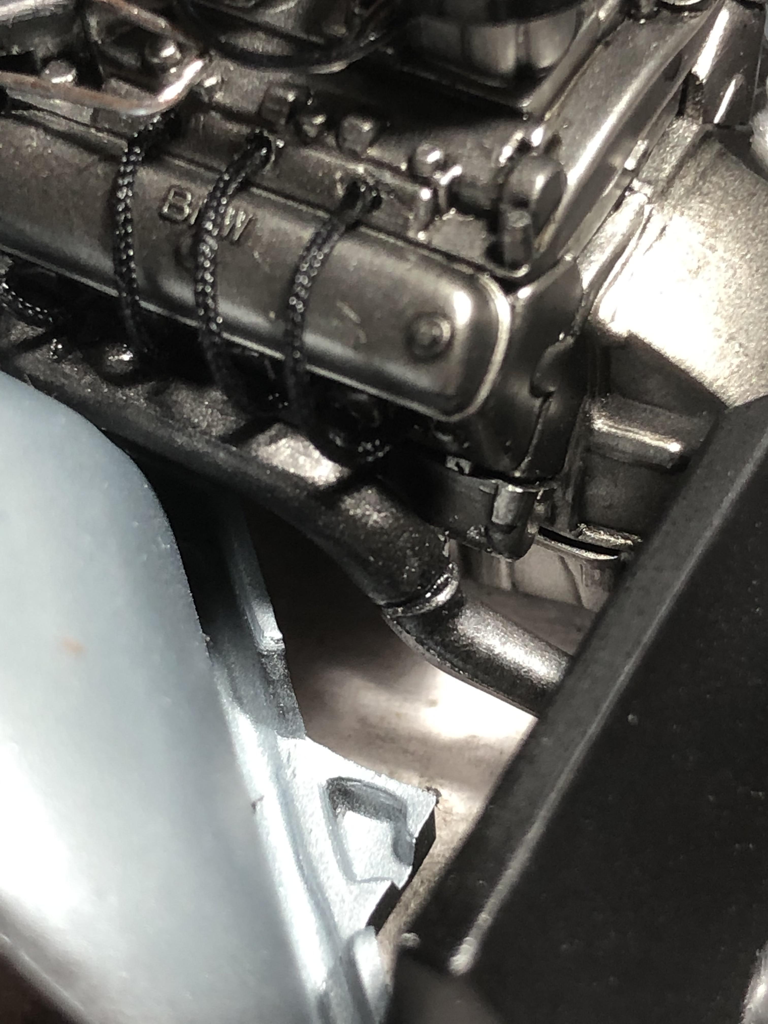
The BMW 507 Coupé’s power unit was an aluminium-alloy pushrod-operated overhead-valve V8 unit, displacing 3,168 cc (193.3 cubic inches). It breathed through two Zenith 32NDIX two-barrel carburettors, and featured a chain-driven oil pump, high-lift cams, a different spark advance curve compared to the associated saloon models, polished combustion chambers, and a compression ratio of 7.8:1. Power output was claimed to be 150 metric horsepower (110kW) DIN at 5,000rpm. This impressive-looking – and sounding – power unit was mated to a close-ratio four-speed manual transmission. The standard final-drive ratio was selected as 3.70:1, with options of 3.42:1 and 3.90:1 optional.

A contemporary road test of a BMW 507 with the standard 3.70:1 final drive appeared in the Swiss magazine Motor Revue, citing 0-100km/h (0-62mph) acceleration in 11.1 seconds and a top speed of 122mph - heady figures for 1956-57. Here indeed was a rocket ship for the public road.

The brand-new BMW 507 made its debut at the Waldorf-Astoria Hotel in New York in the summer of 1955 and production began in November 1956. Max Hoffman intended the 507 to sell for some US $5,000, which he believed would support a production run of 5,000 units a year. However, production costs of this svelte new German beauty ran away with the project, and the German market price inflated relentlessly: first to DM 26,500 and later 29,950, which pushed up the US market price initially to $9,000 and then $10,500.

The 507 Spyder and Coupé’s undoubtedly startling looks attracted such celebrity customers as Elvis Presley (who owned two), and Hollywood movie director John Derek, while in Germany pre-war Grand Prix racing champion Hans Stuck and motorcycling star Georg ‘Schorsch’ Meier became prominent owners.

Despite having been conceived to revive BMW’s sporting image, and to drive brand perception and sales volume forward, the 507 failed to attract more than 10 per cent of the sales volumes enjoyed by its Stuttgart rival, the six-cylinder Mercedes-Benz 300 SL. Yet for many it was an infinitely better looking, more glamorous, lighter handling – and rapid – alternative.

Their sales difficulties with the 507 instead took BMW to the edge of bankruptcy. In 1959 the Munich company’s losses reached DM 15 million. The company lost money on every 507 built, and when production was abandoned late in 1959 only 252 had been completed, plus two prototypes. Fortunately for the Bavarian company, an infusion of capital from Herbert Quandt, and the launch of new, cheaper models (the BMW 700 and later the ‘New Class’ 1500) intended for a very different sector of the road car market, helped the company recover, placing it on the launching pad to its continuing success.- Collated from various sources

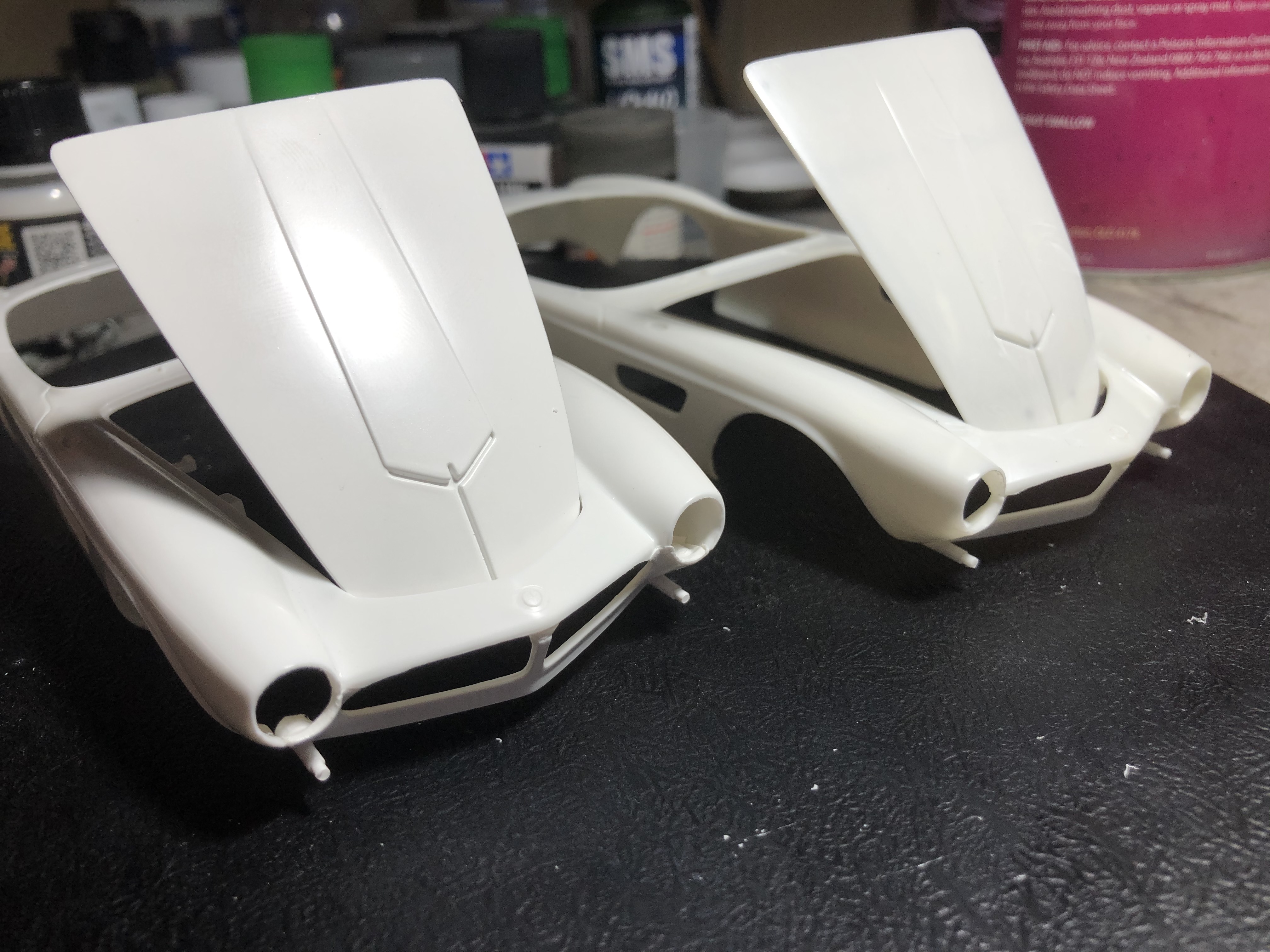
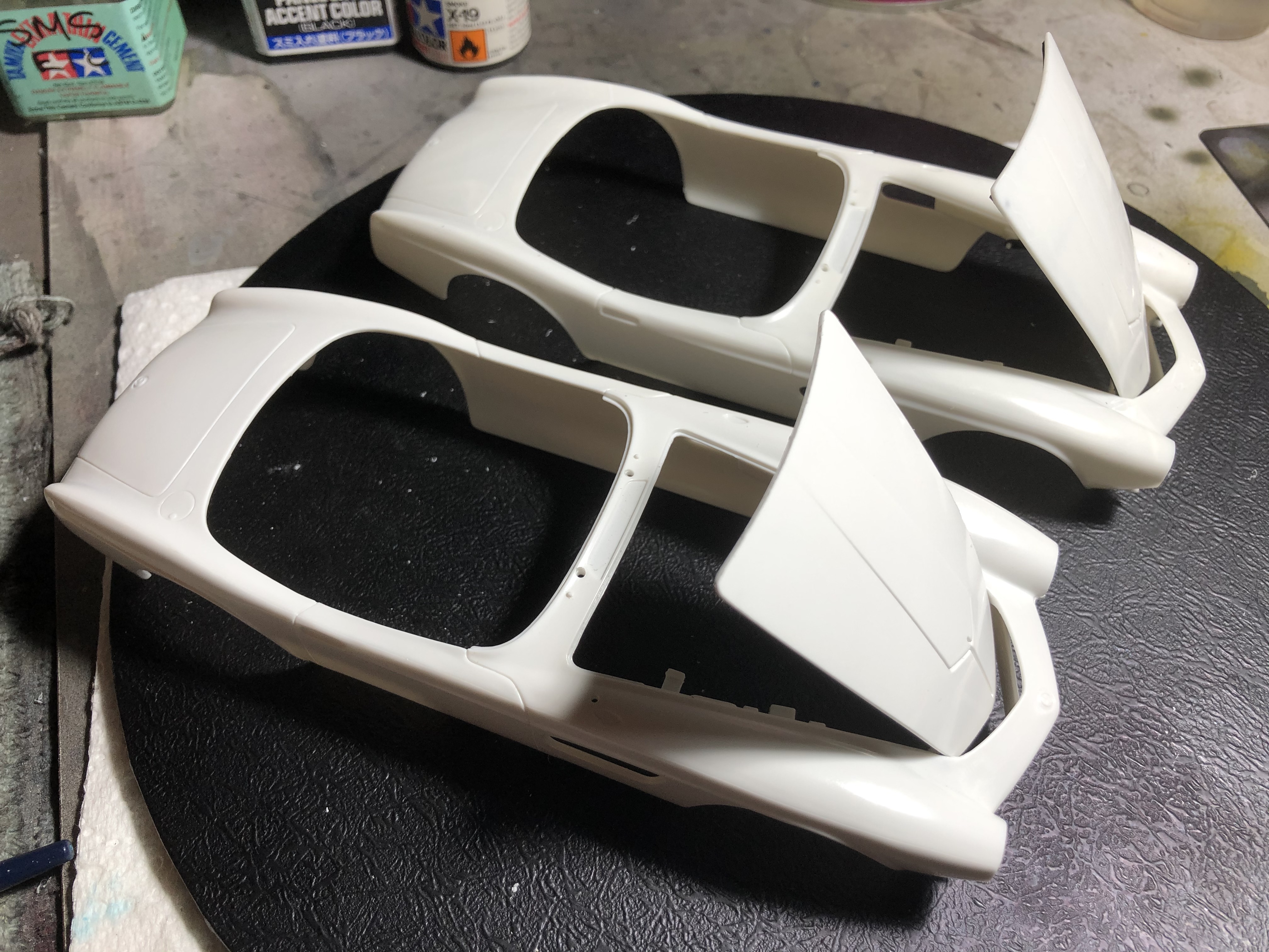
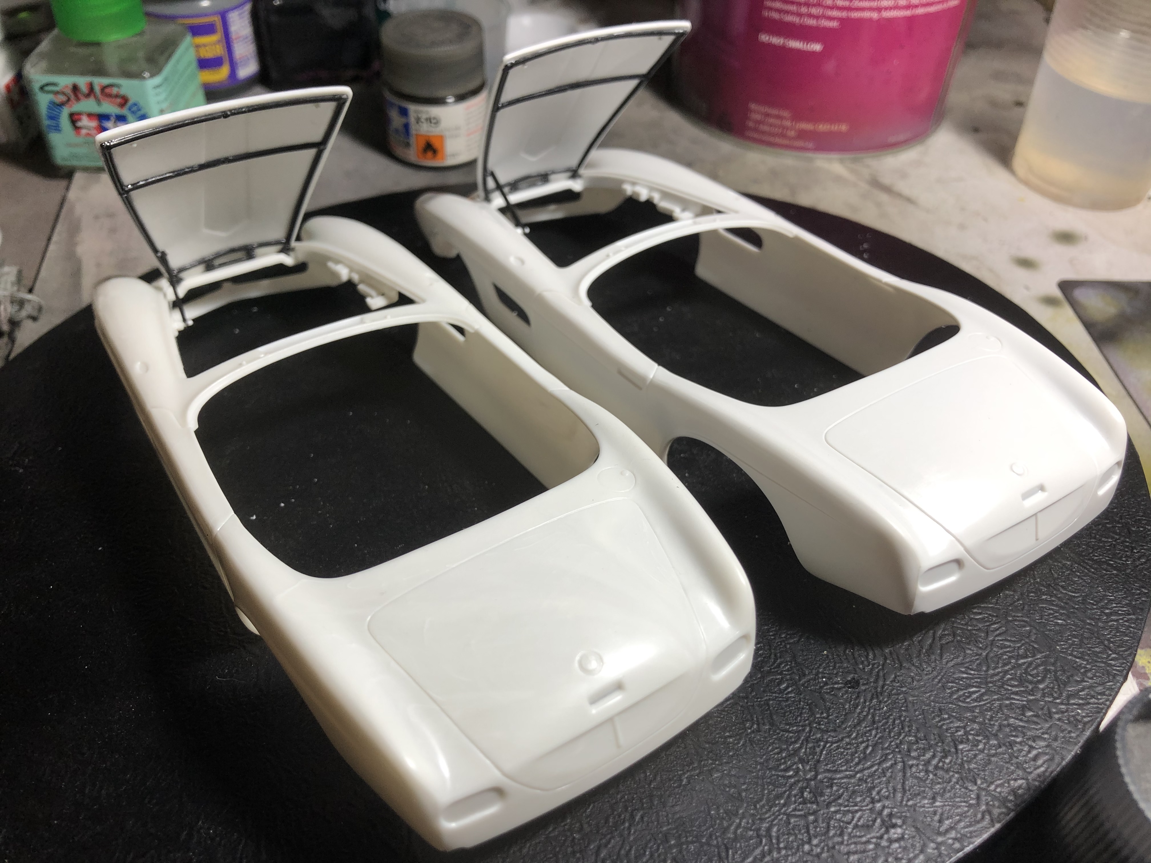
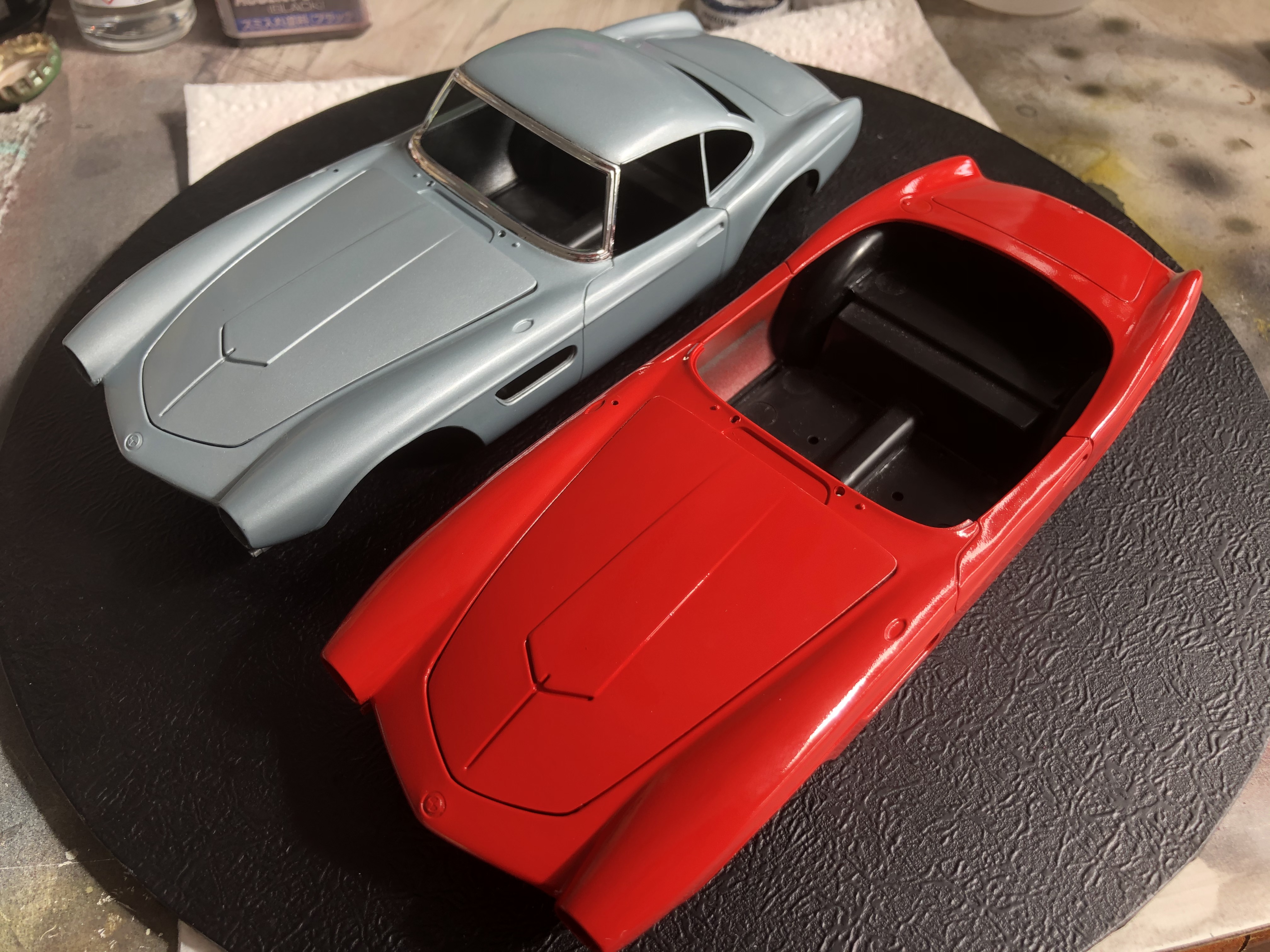
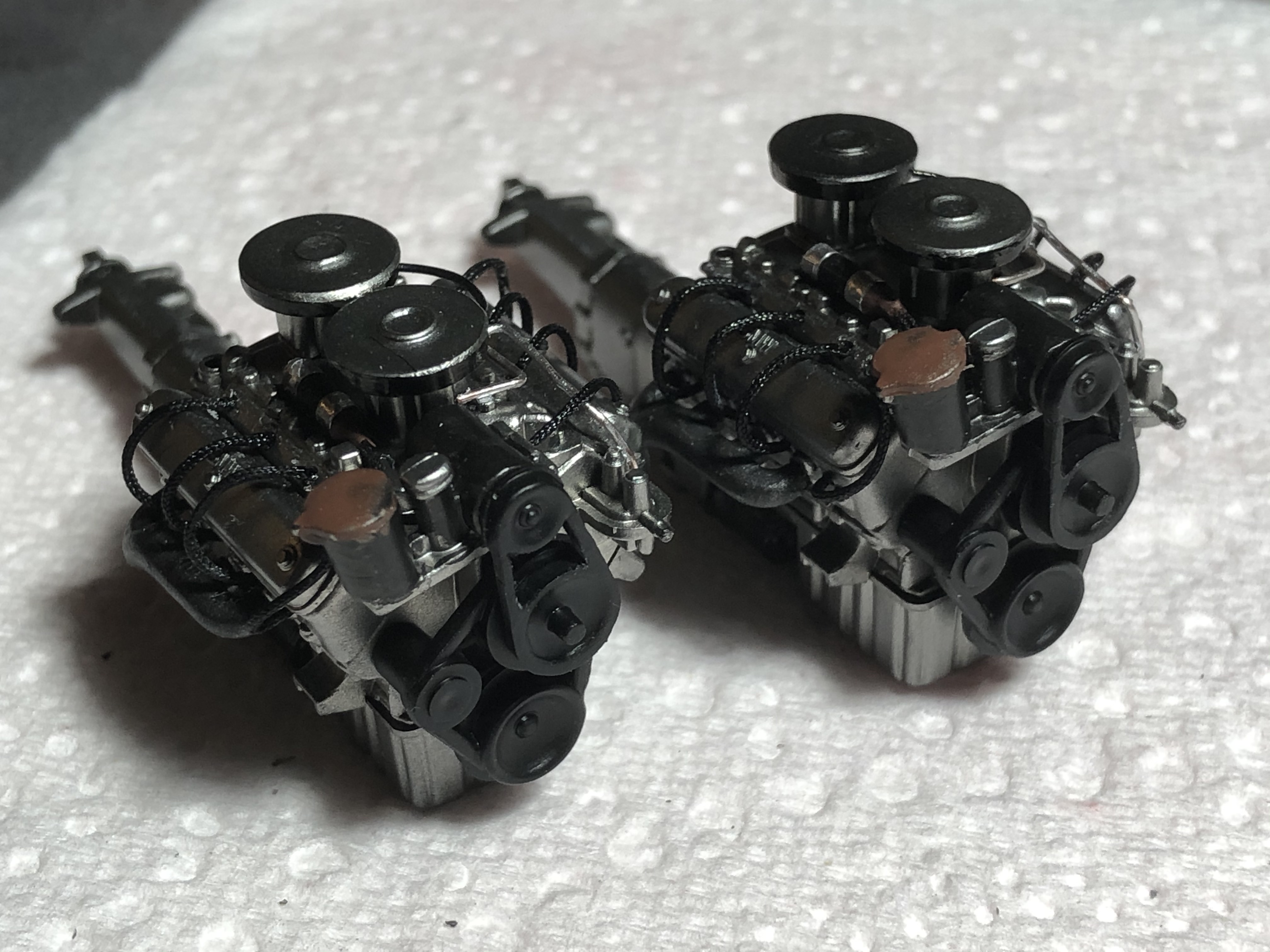
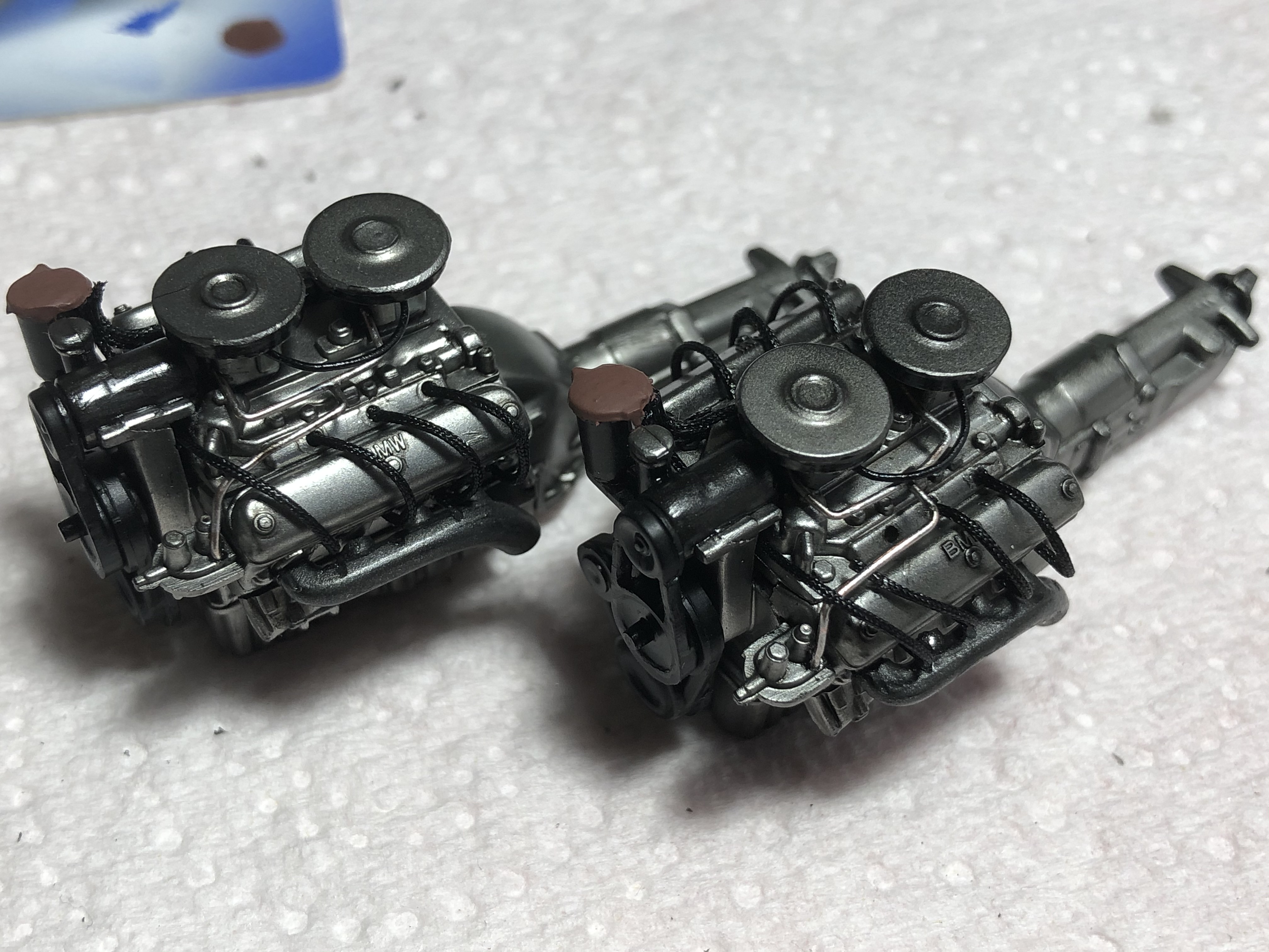
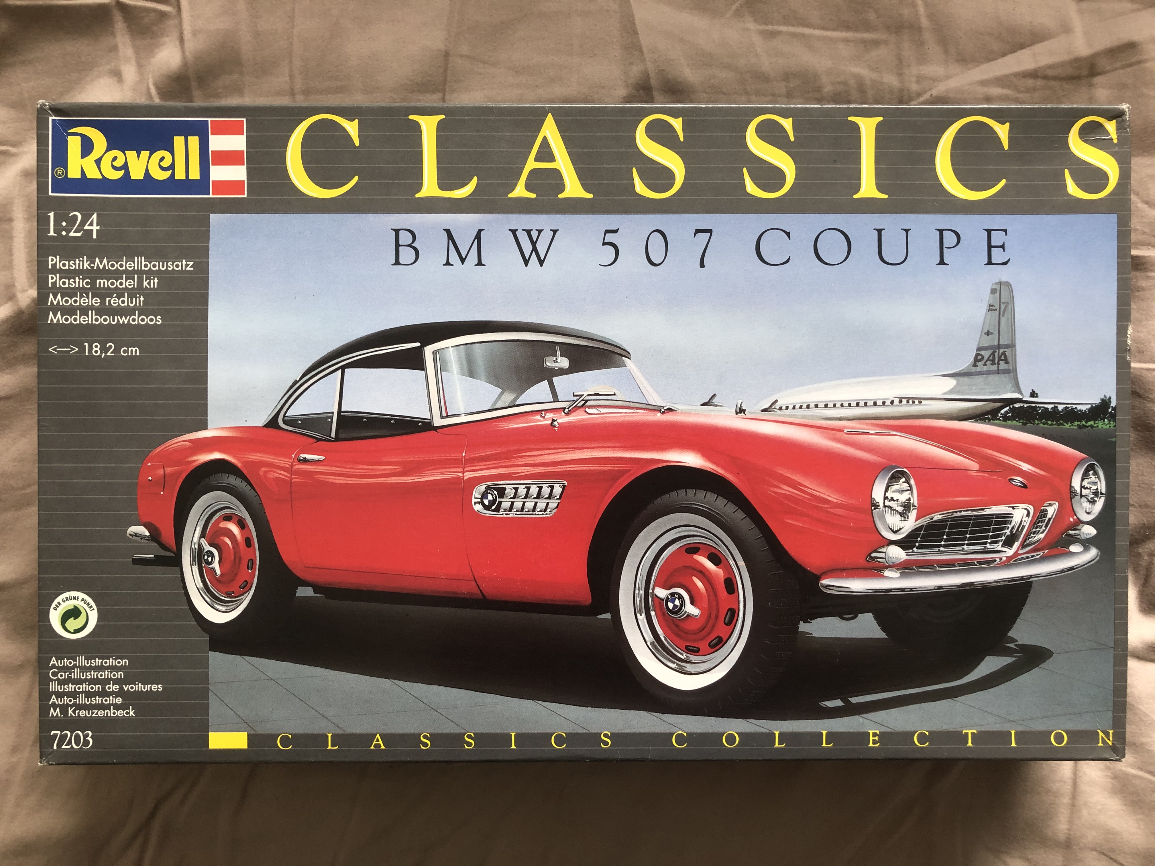
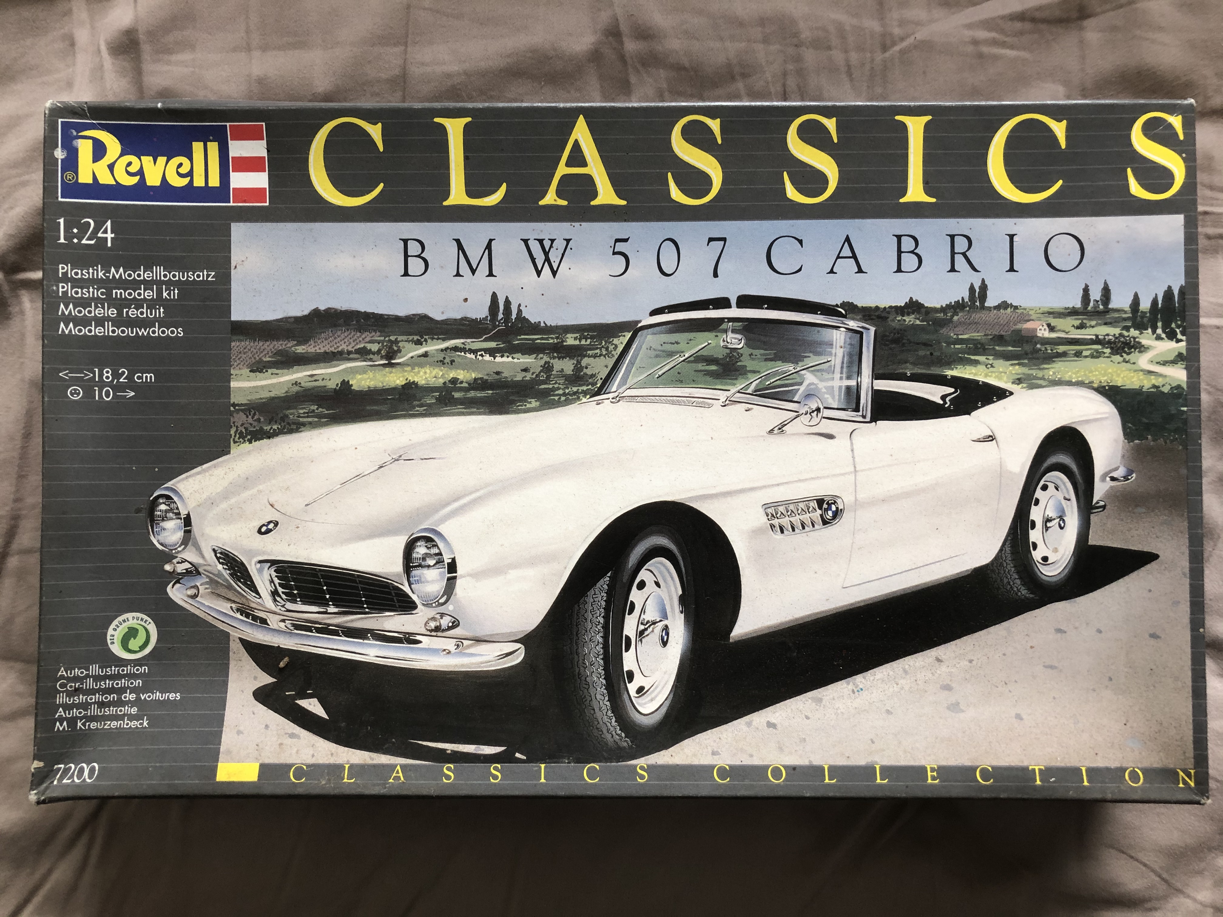
When I saw these 2 kits posted for sale in a stash clearance I was instantly drawn by the classic 50’s lines and chrome, and even though I knew nothing about the car, and had never seen them built or reviewed online, I snapped them up.


Doing some research to look at options for colour schemes, I came across a pair of very significant vehicles that would make a great little display pair.

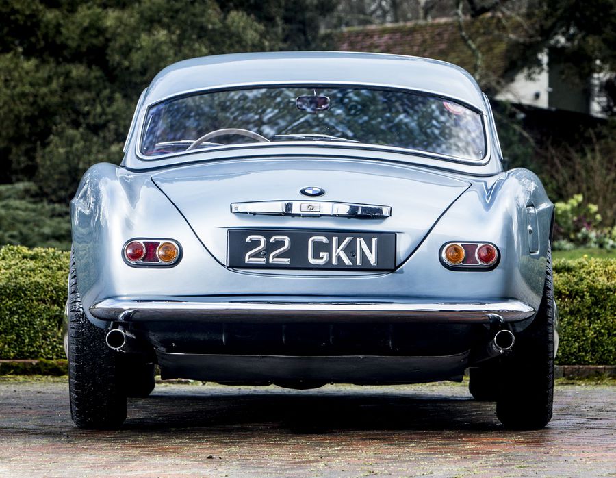
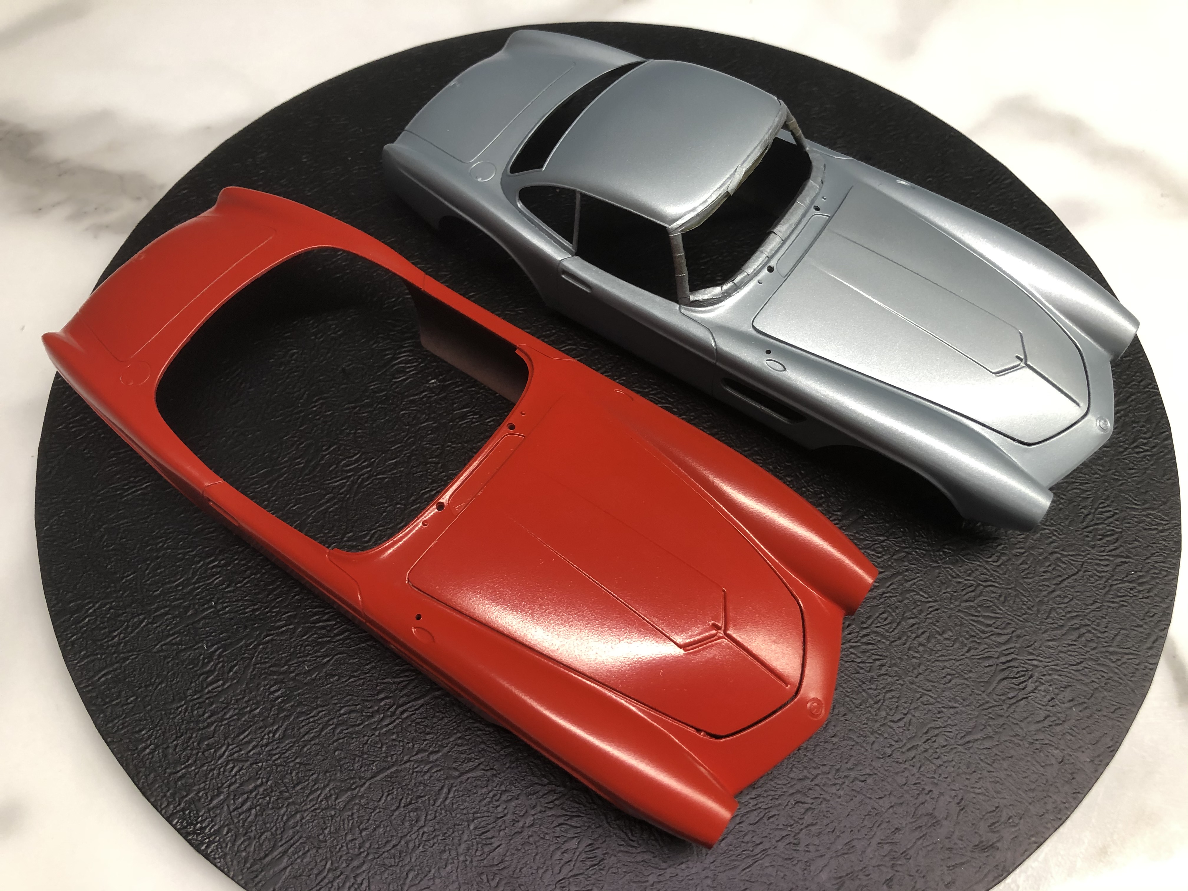
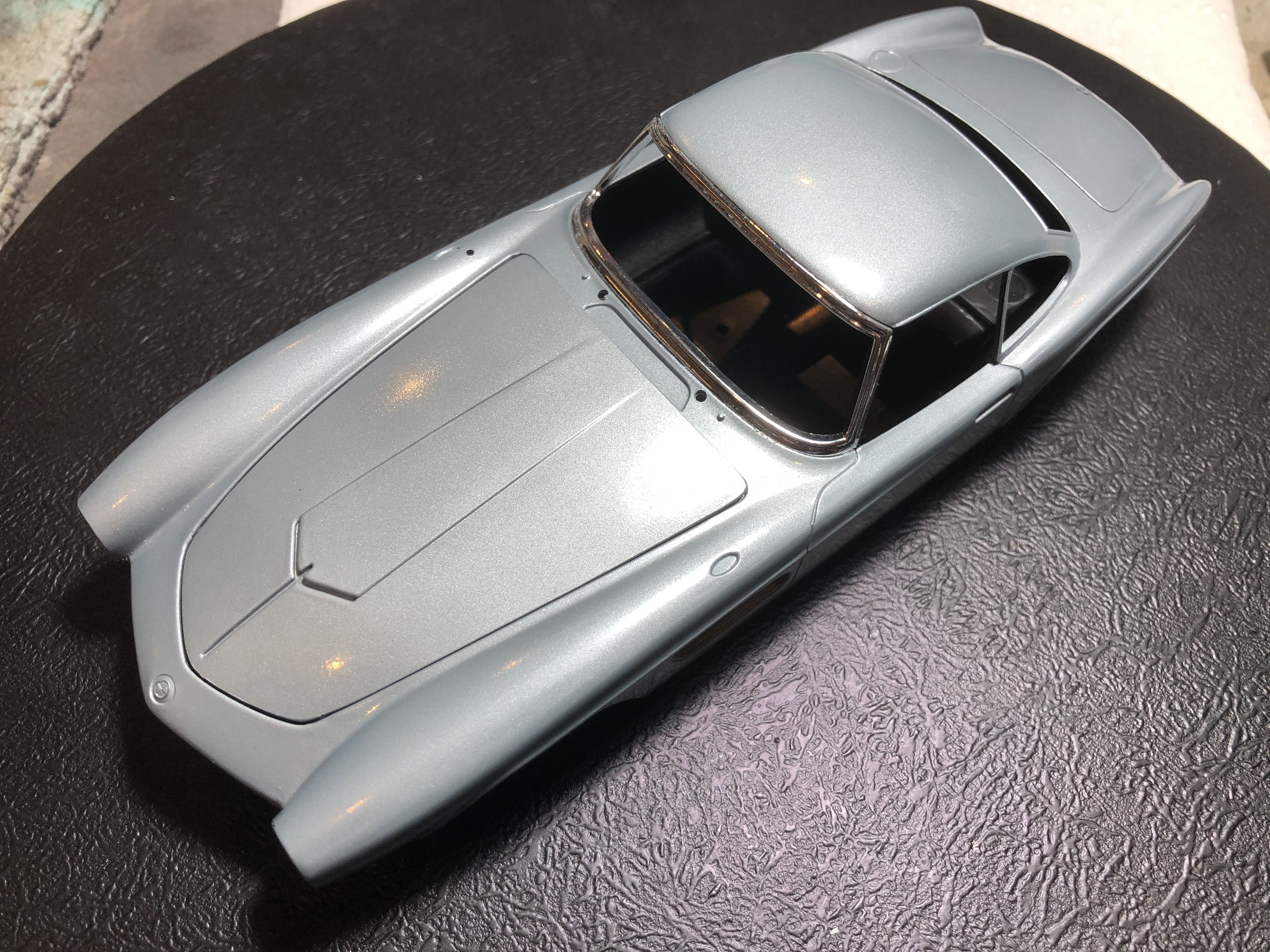
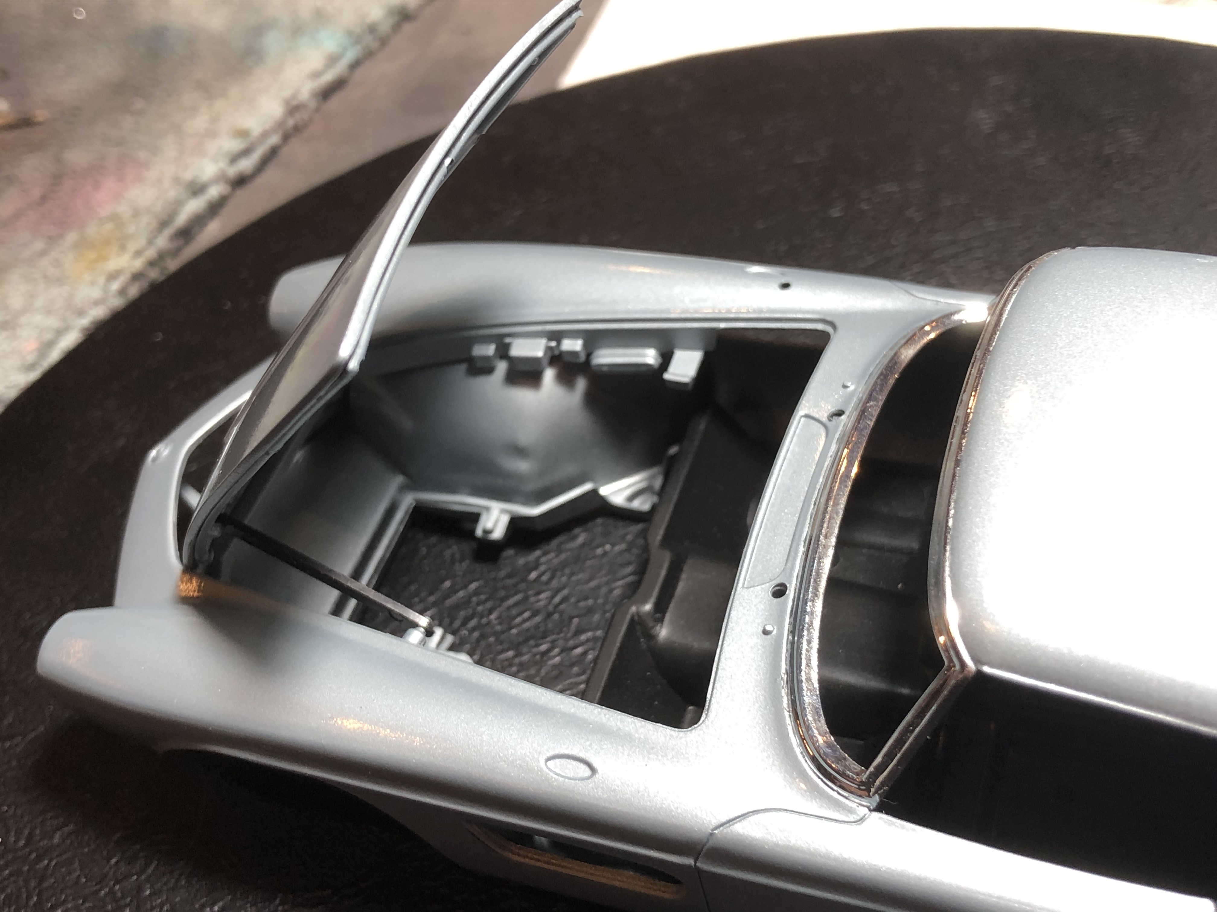
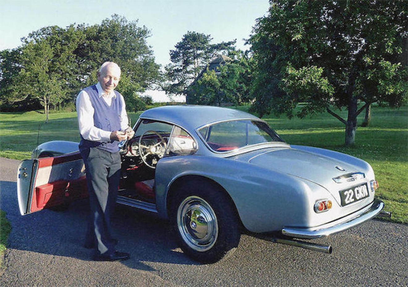
The first is the Coupe owned from new by the legend John Surtees, sold at auction after his death for almost 4 million pounds, in 2018.

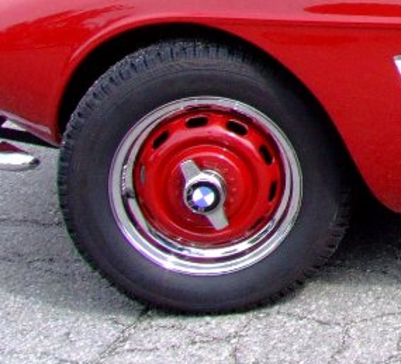
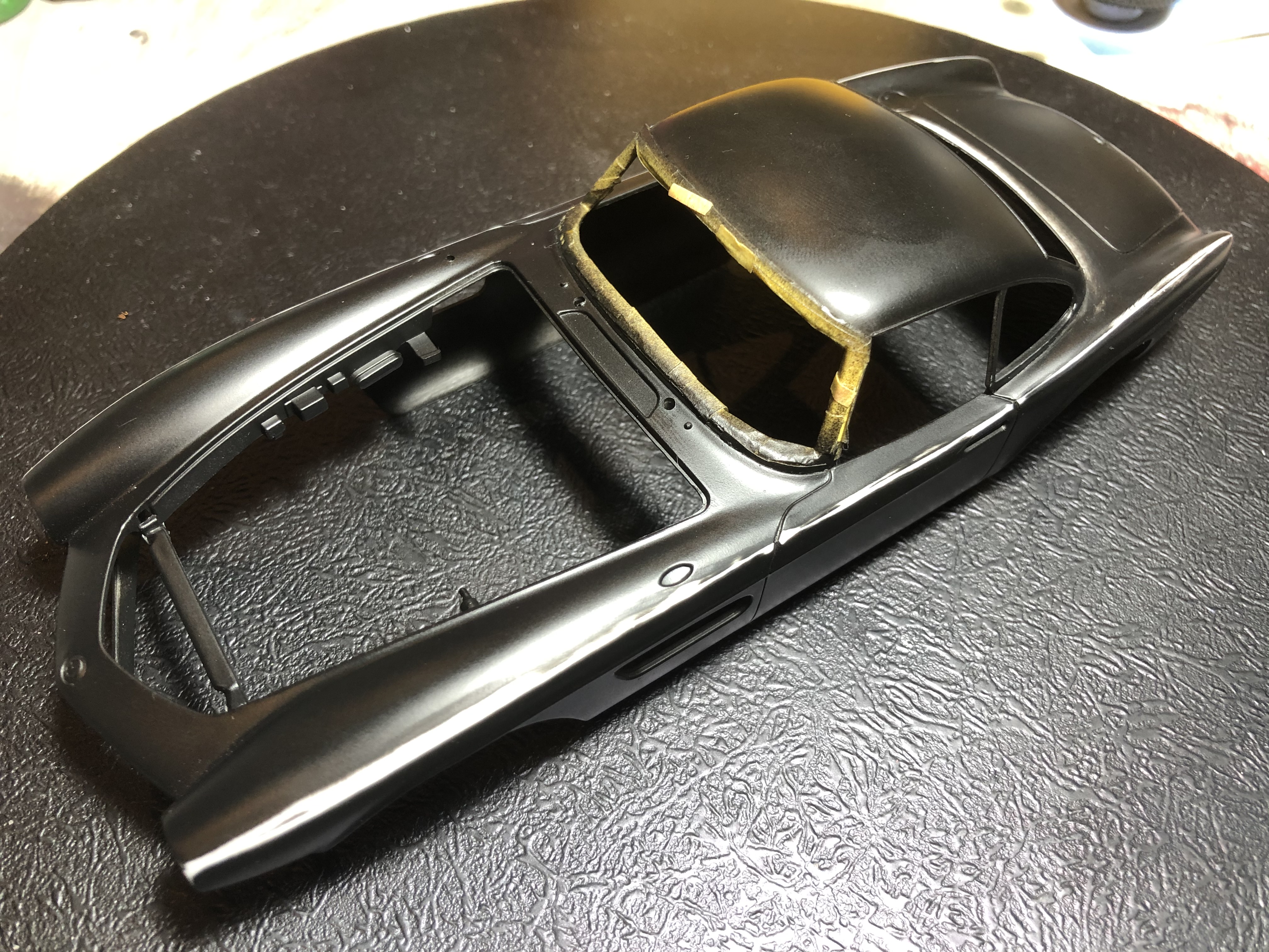
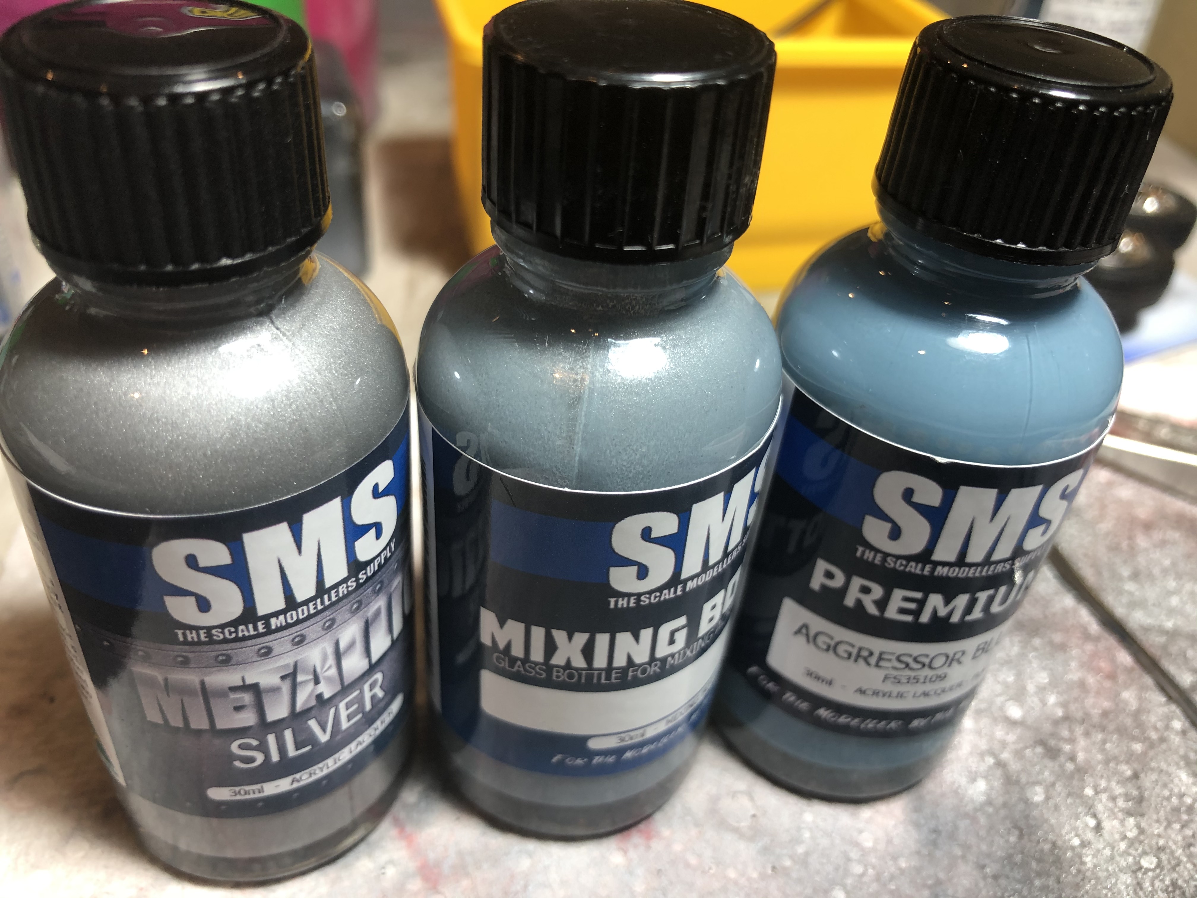
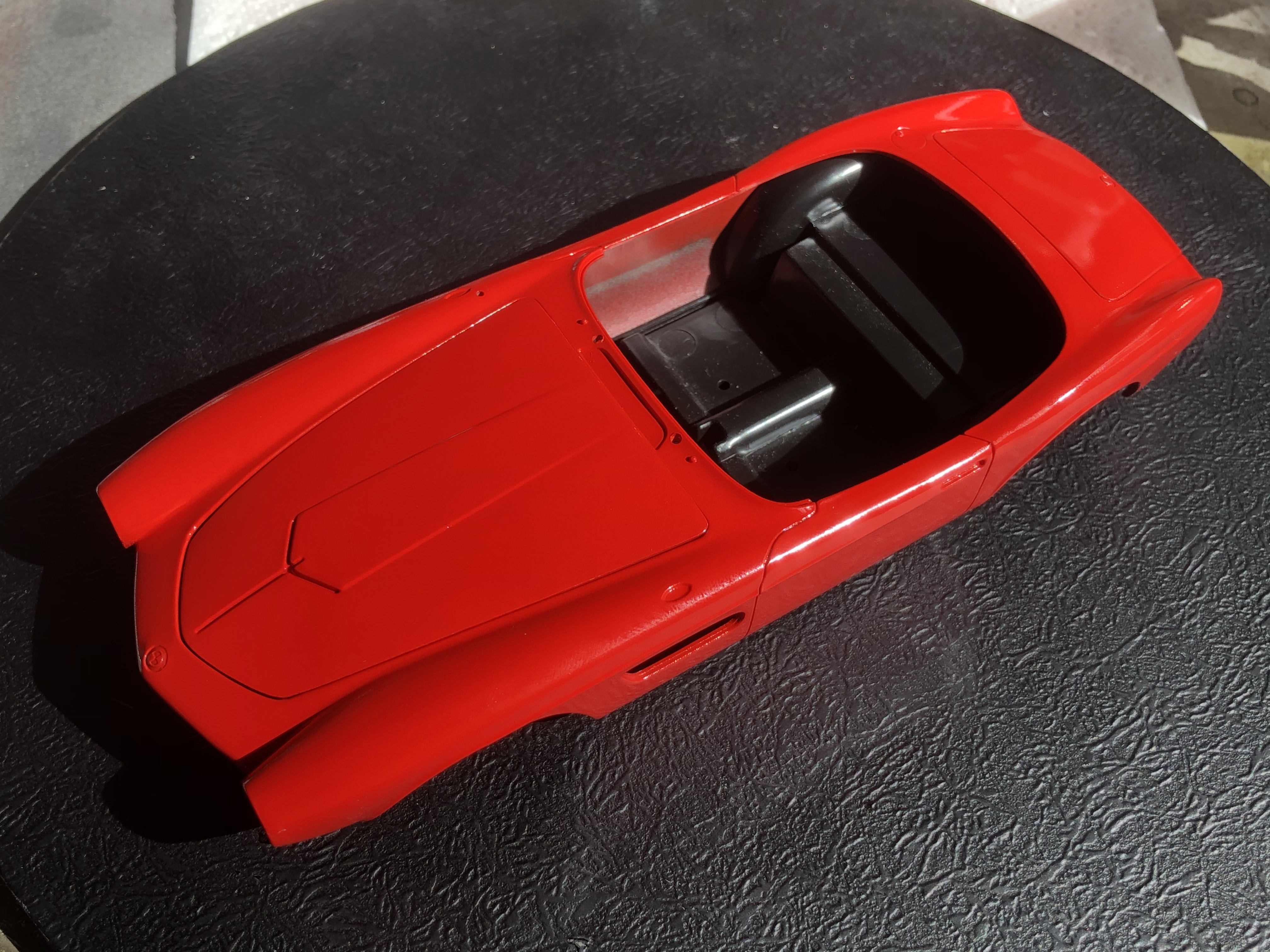
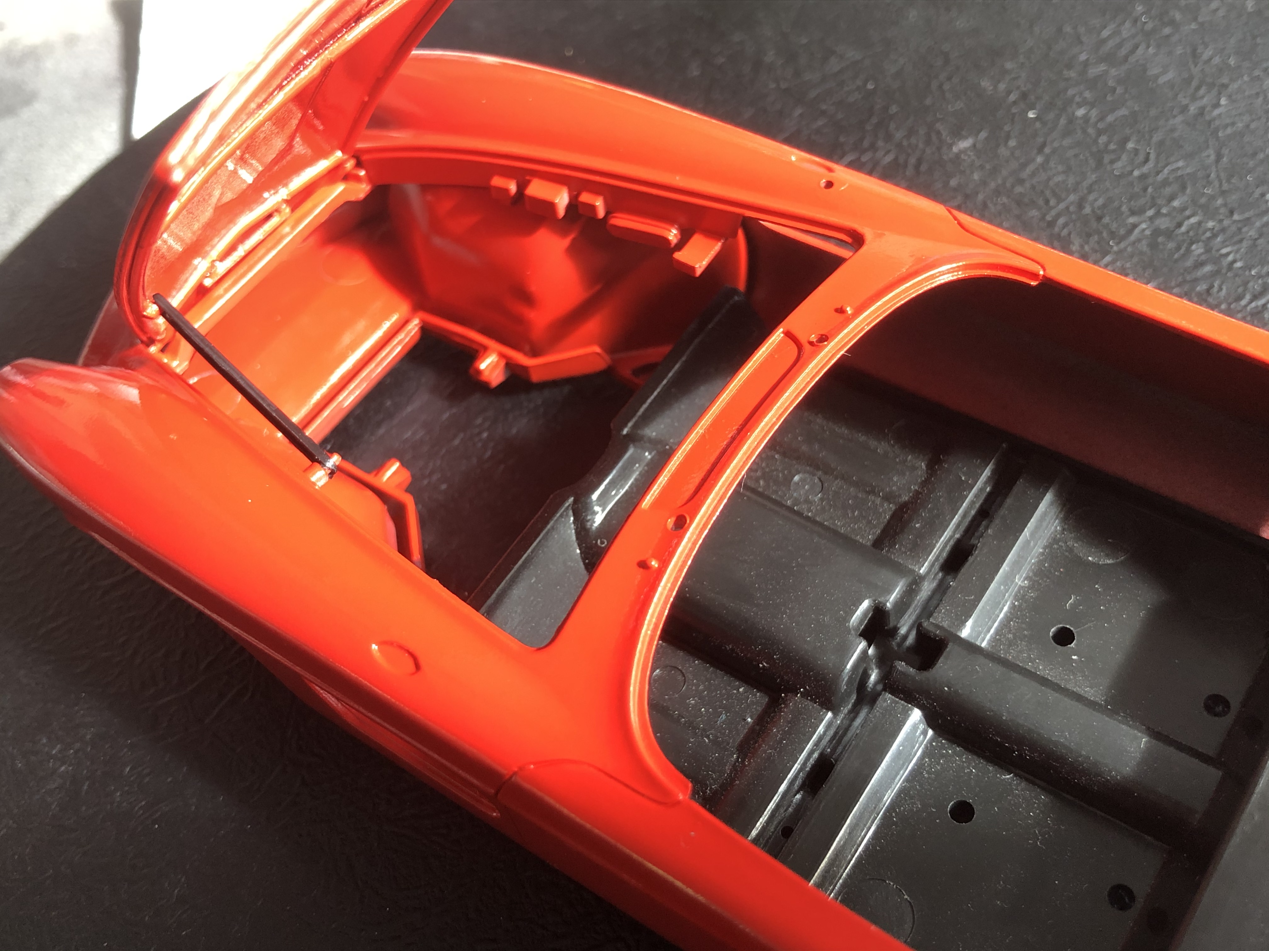
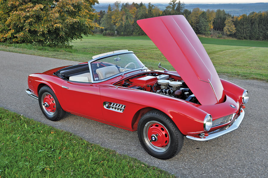
The second is the Cabrio owned by the car’s designer Albrecht von Goertz. This one was originally factory silver-grey the same as the Surtees Coupe, but was repainted in the 90’s, and I like the red body colour.

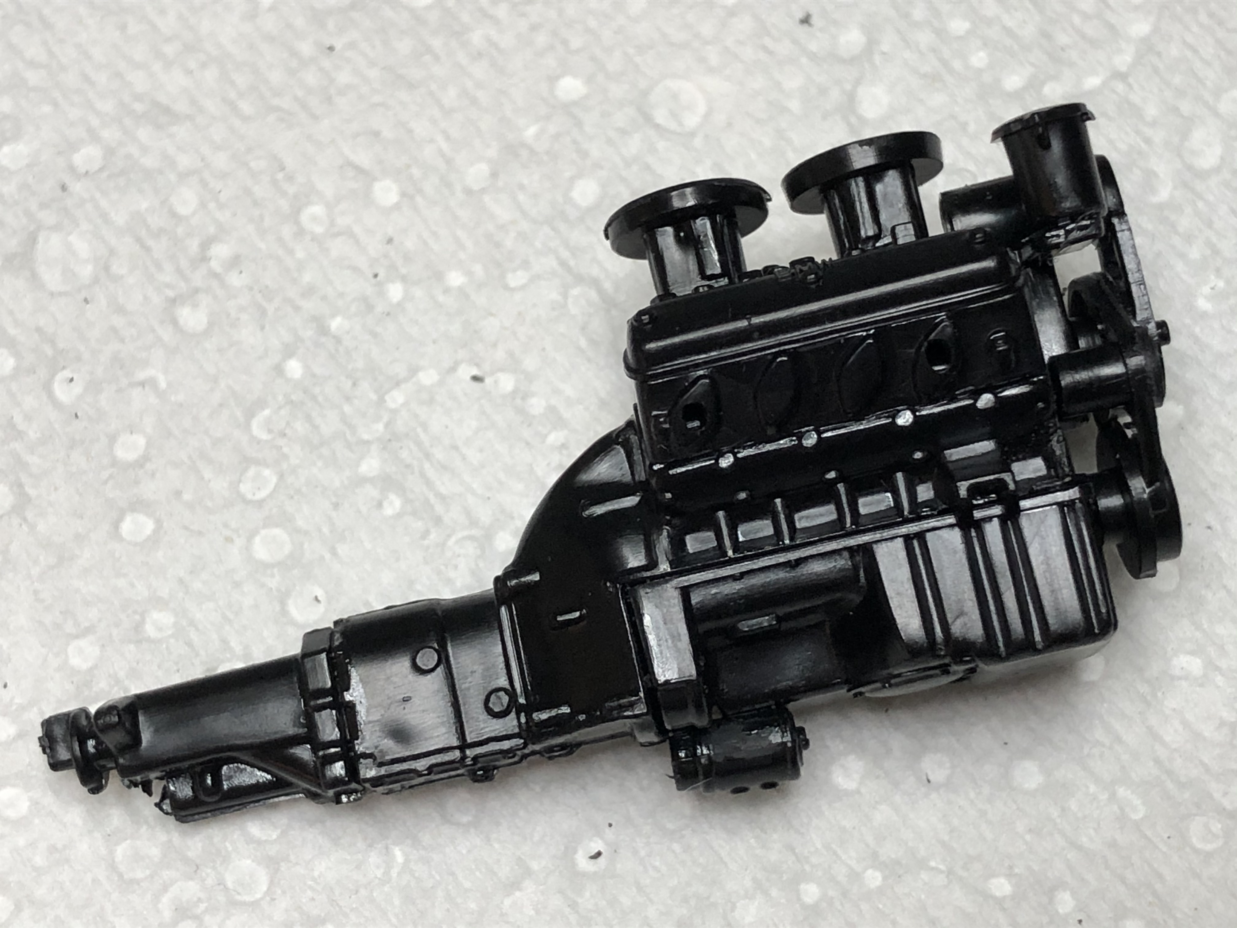
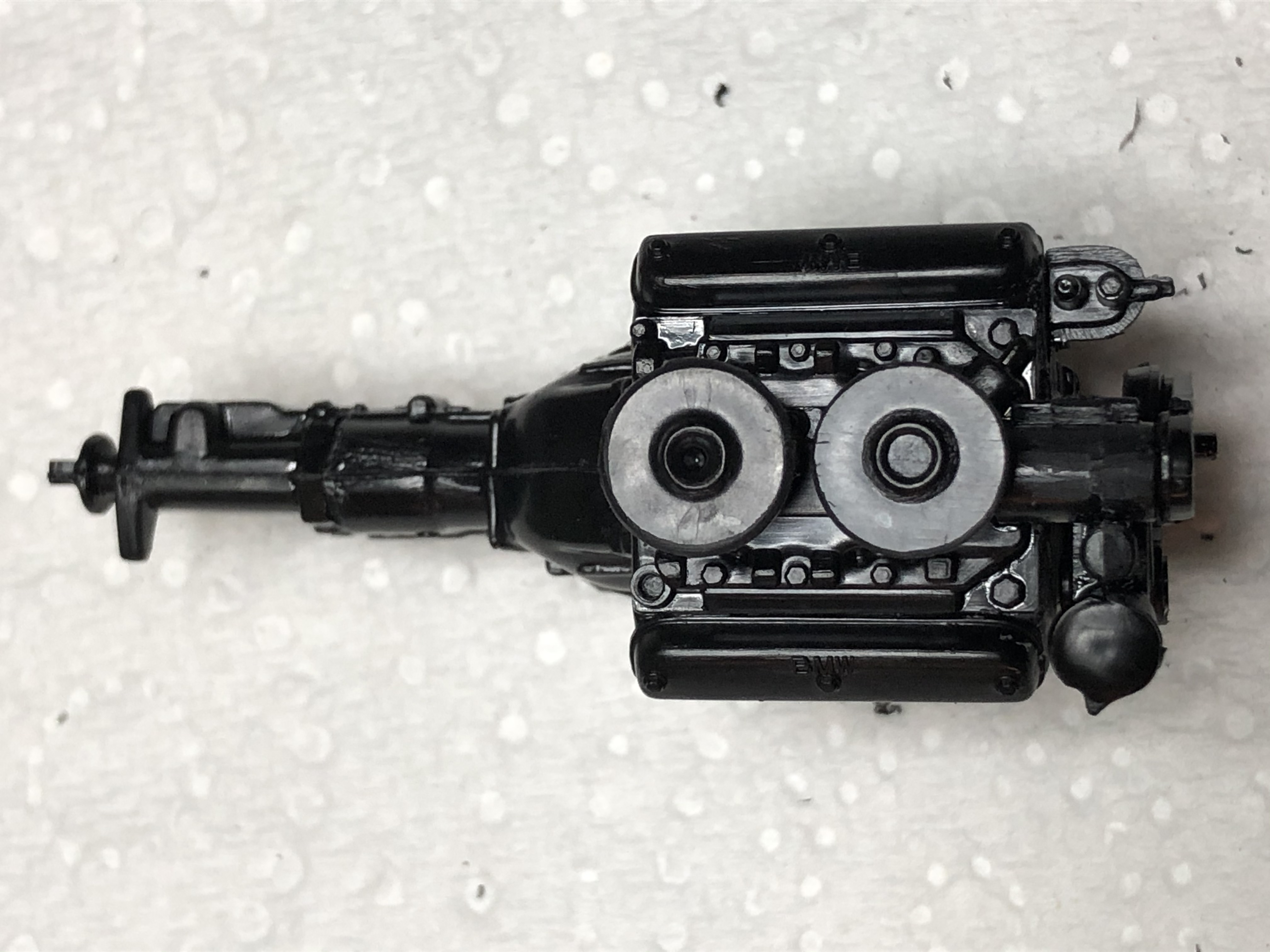
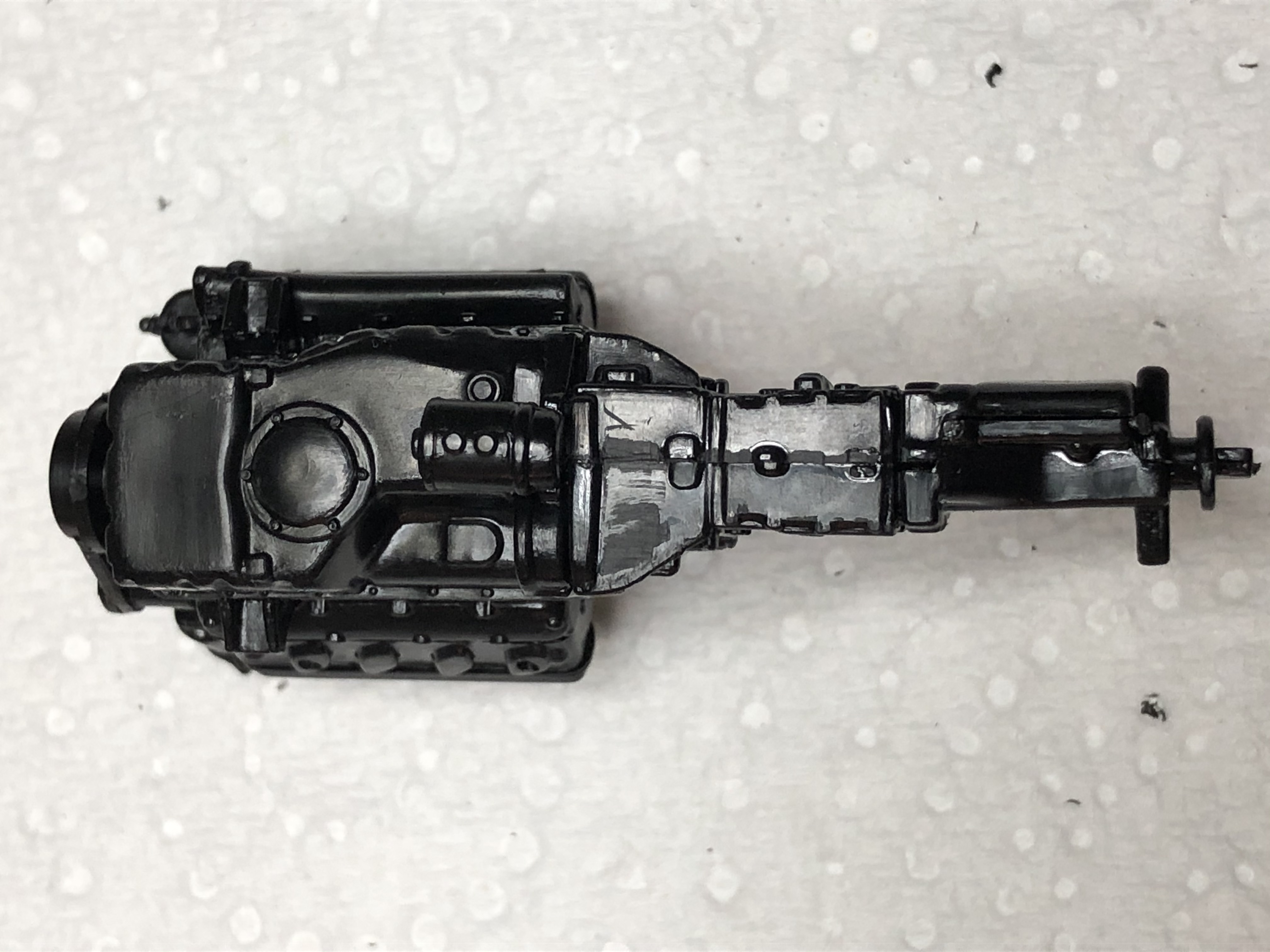
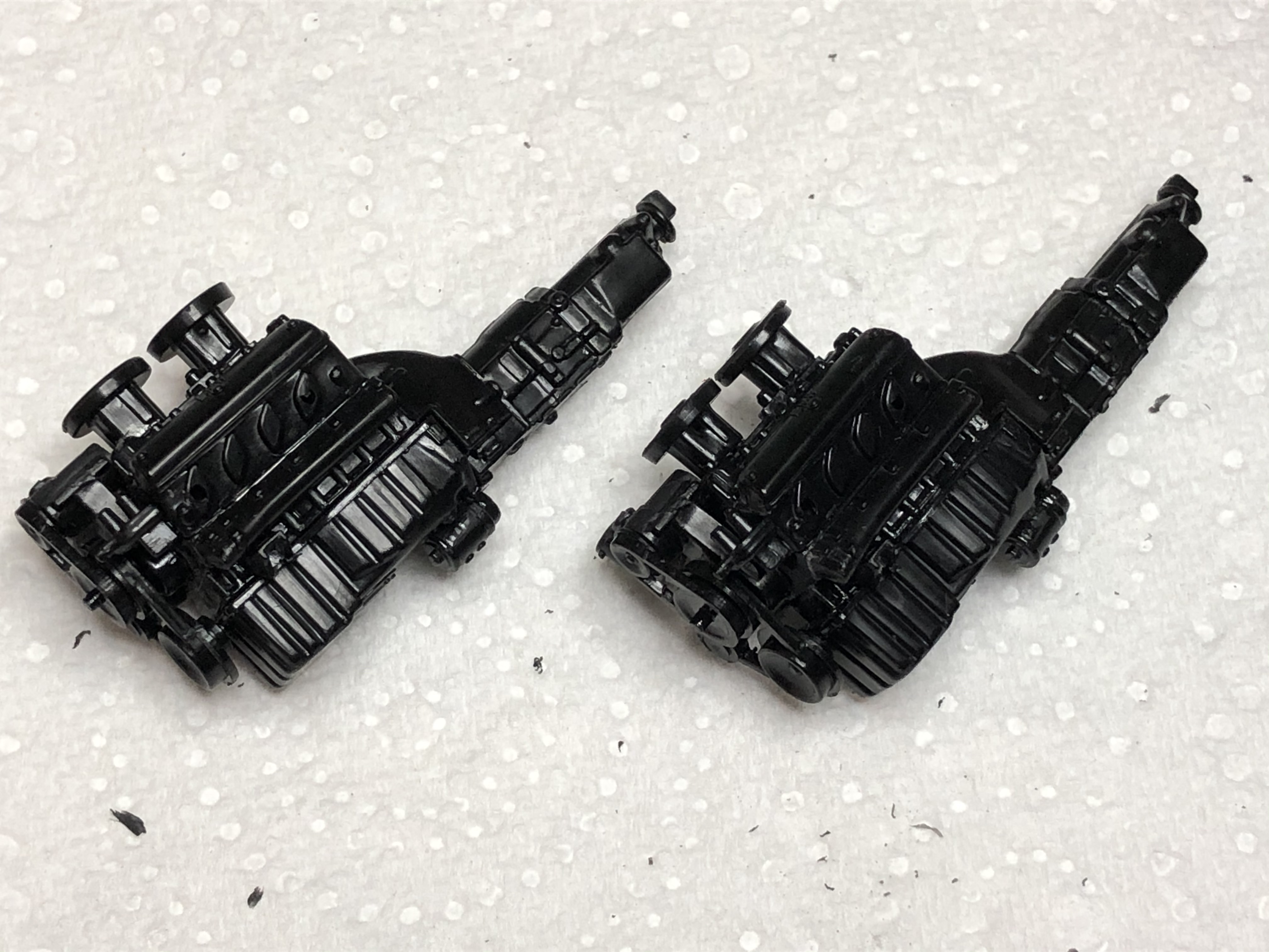
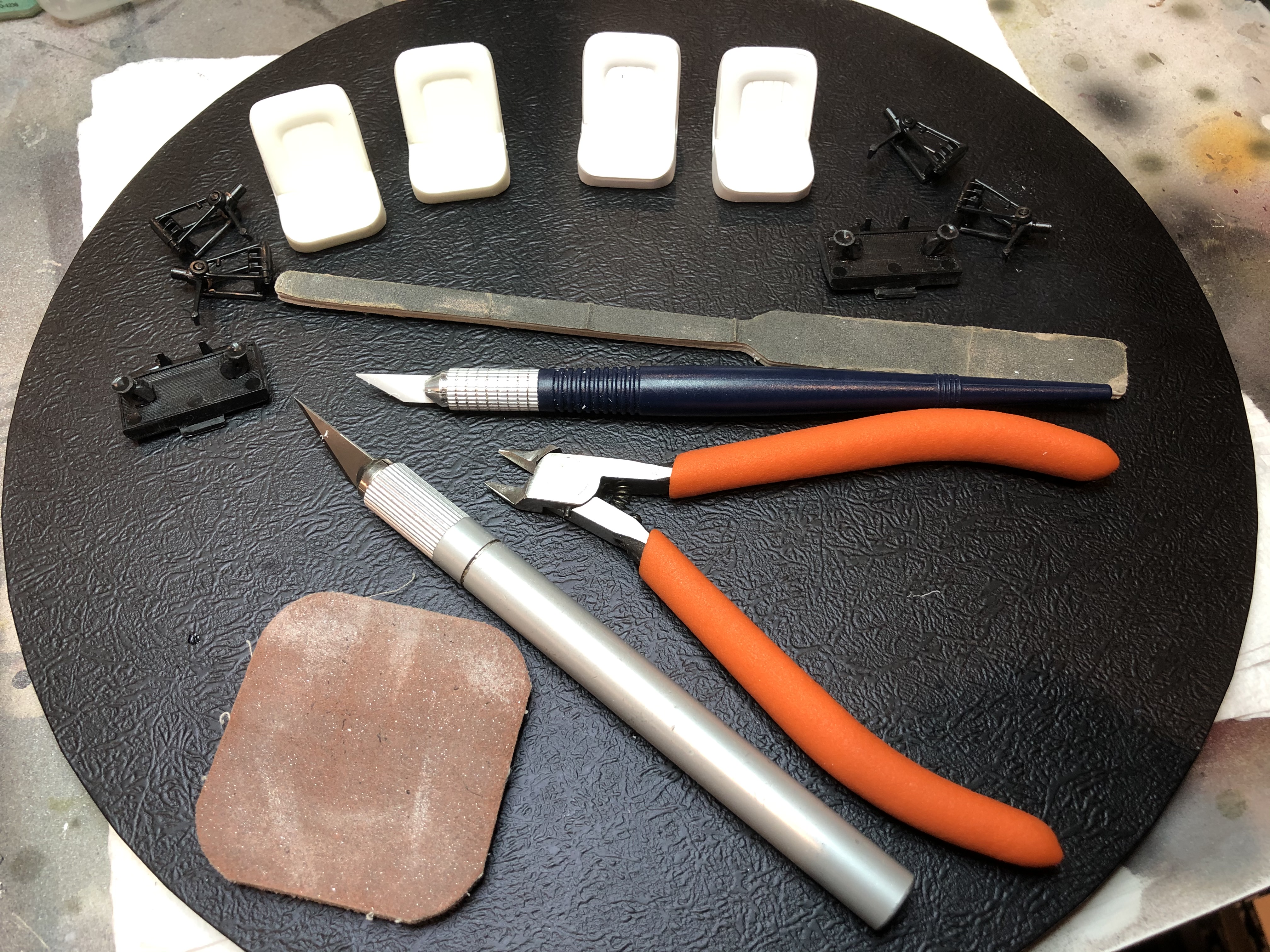
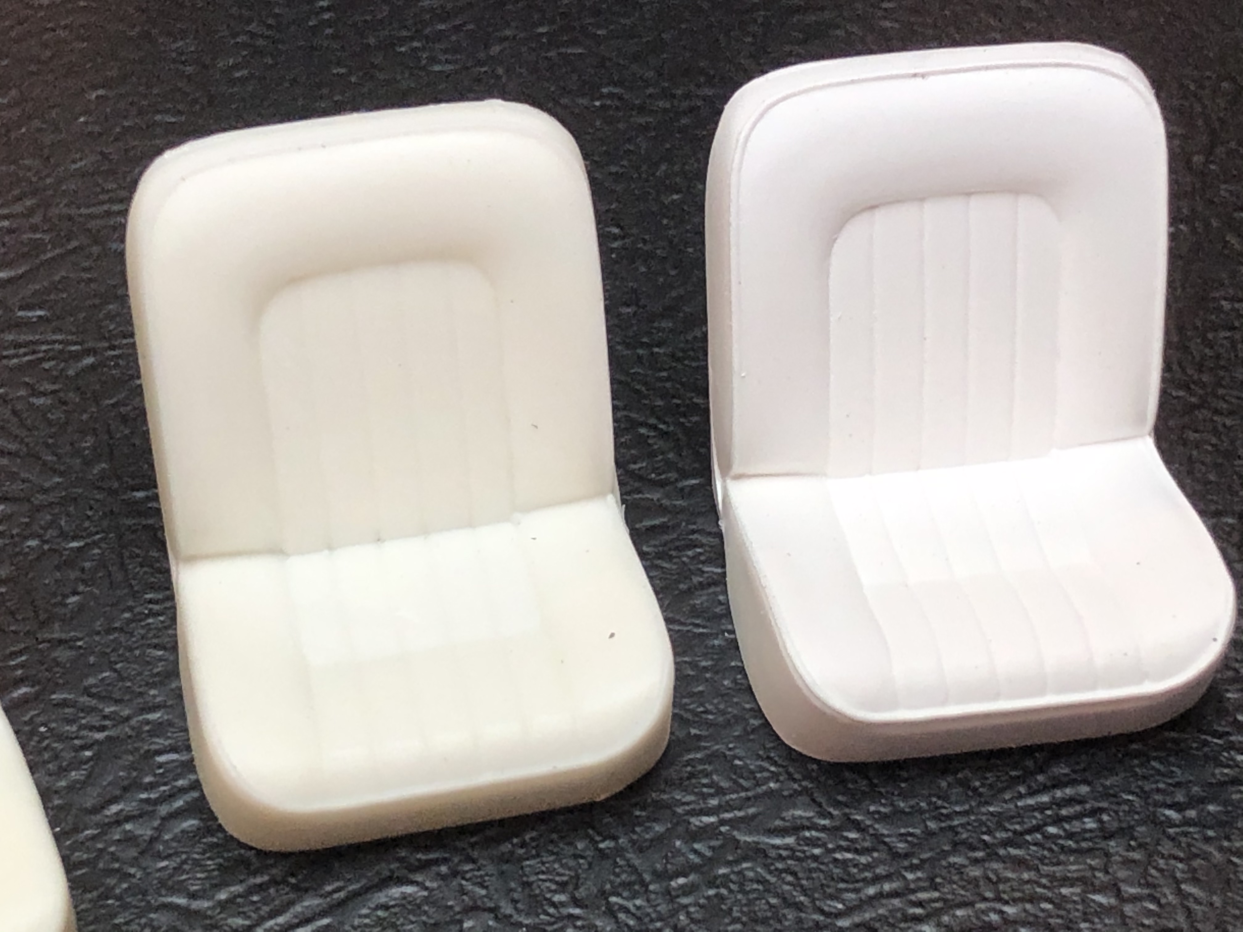
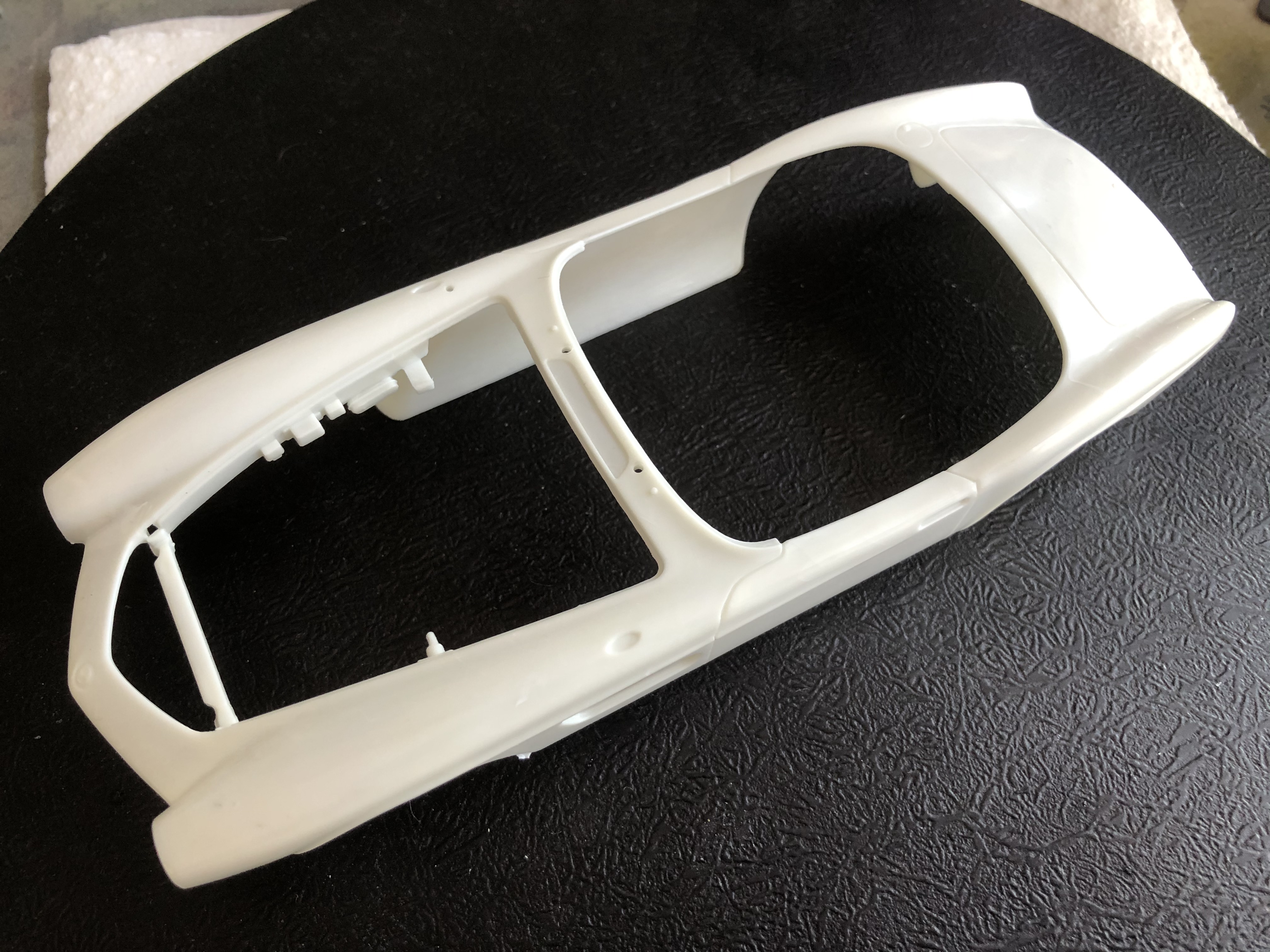
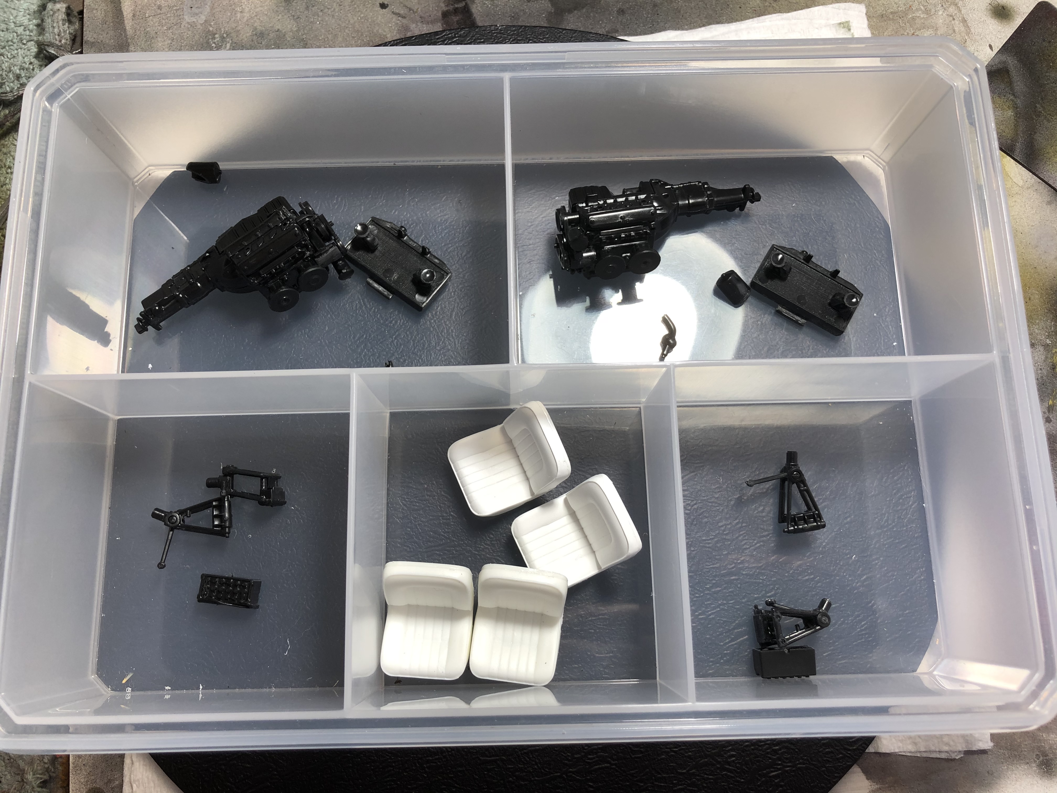
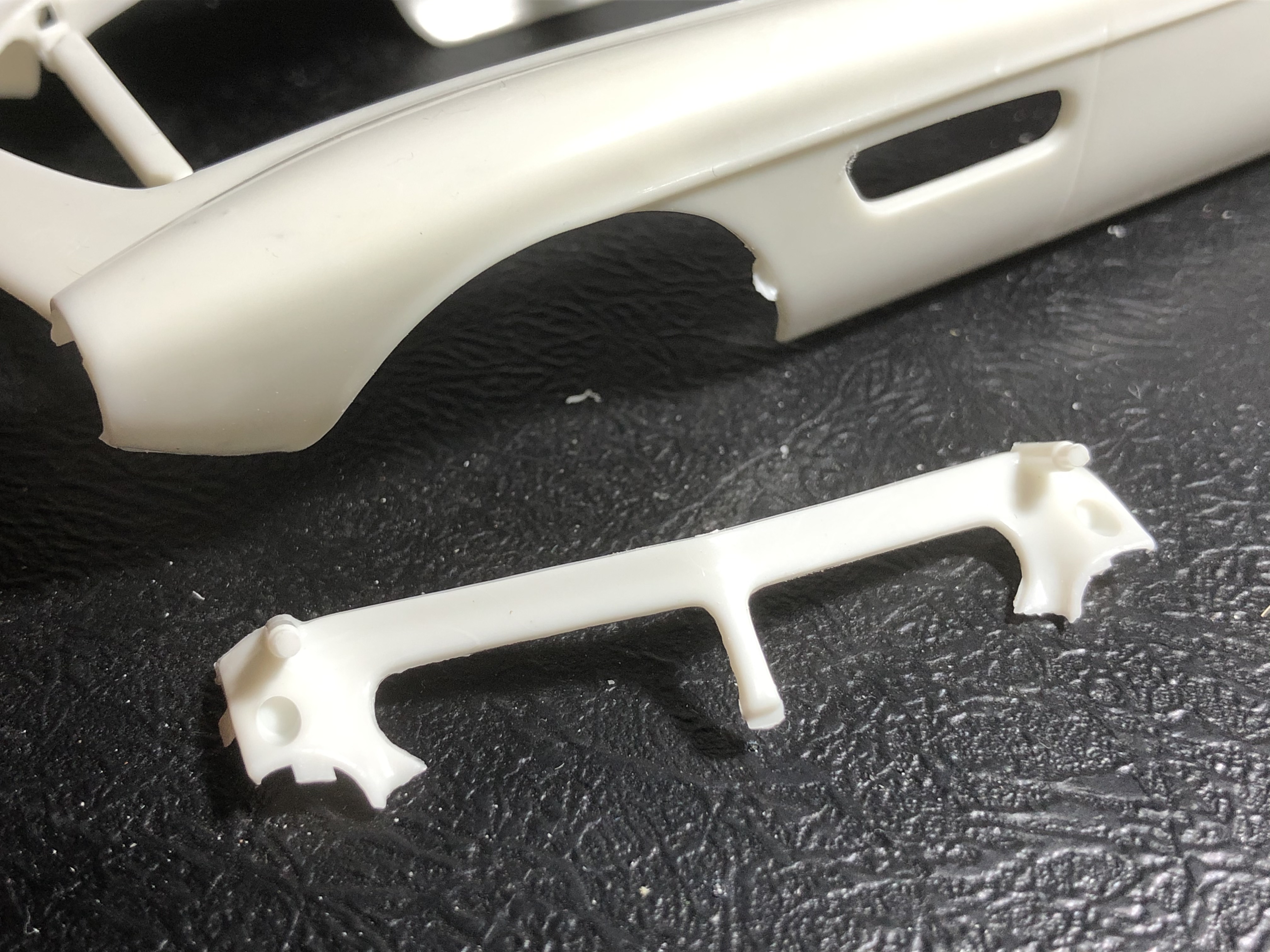
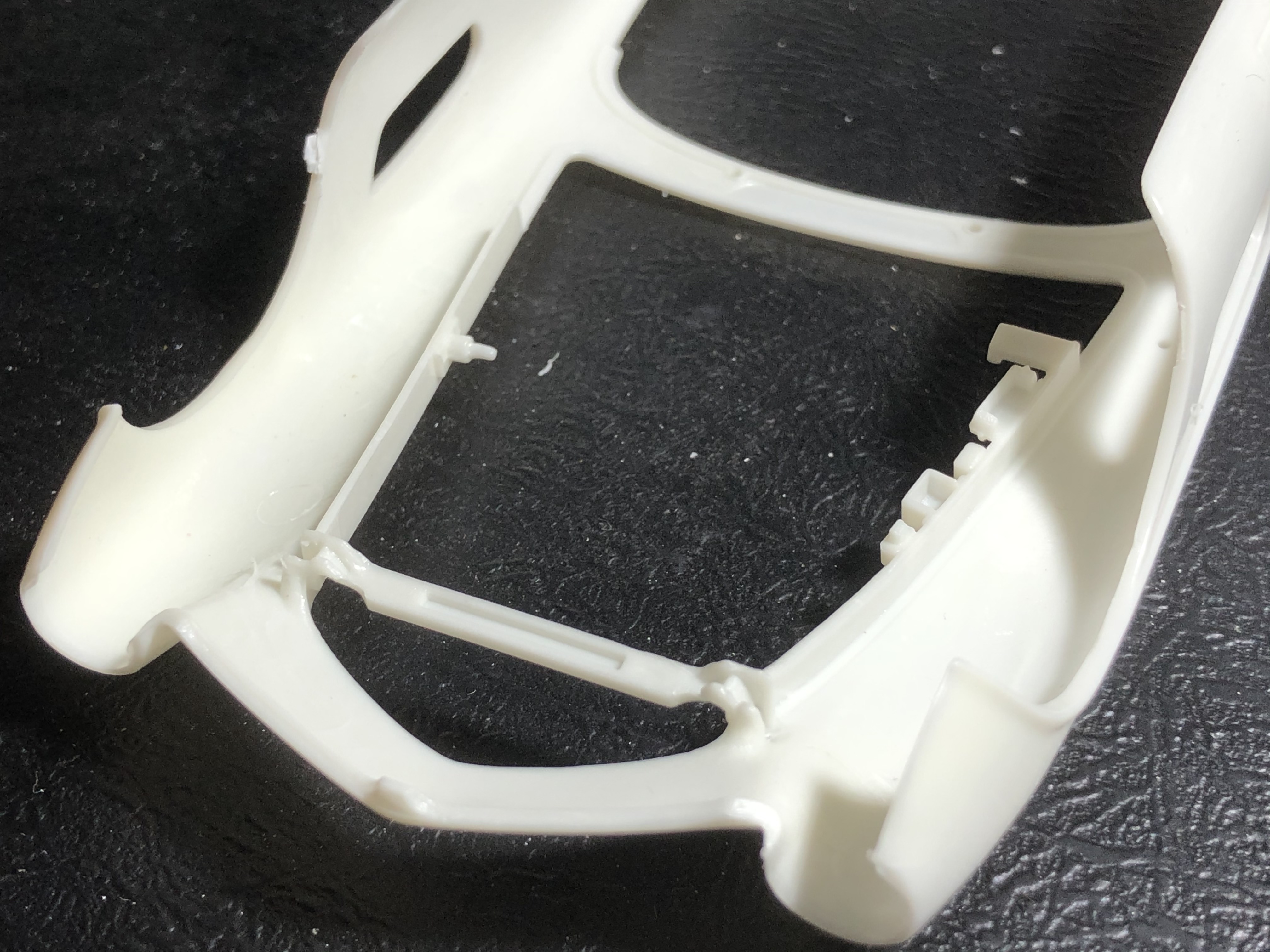
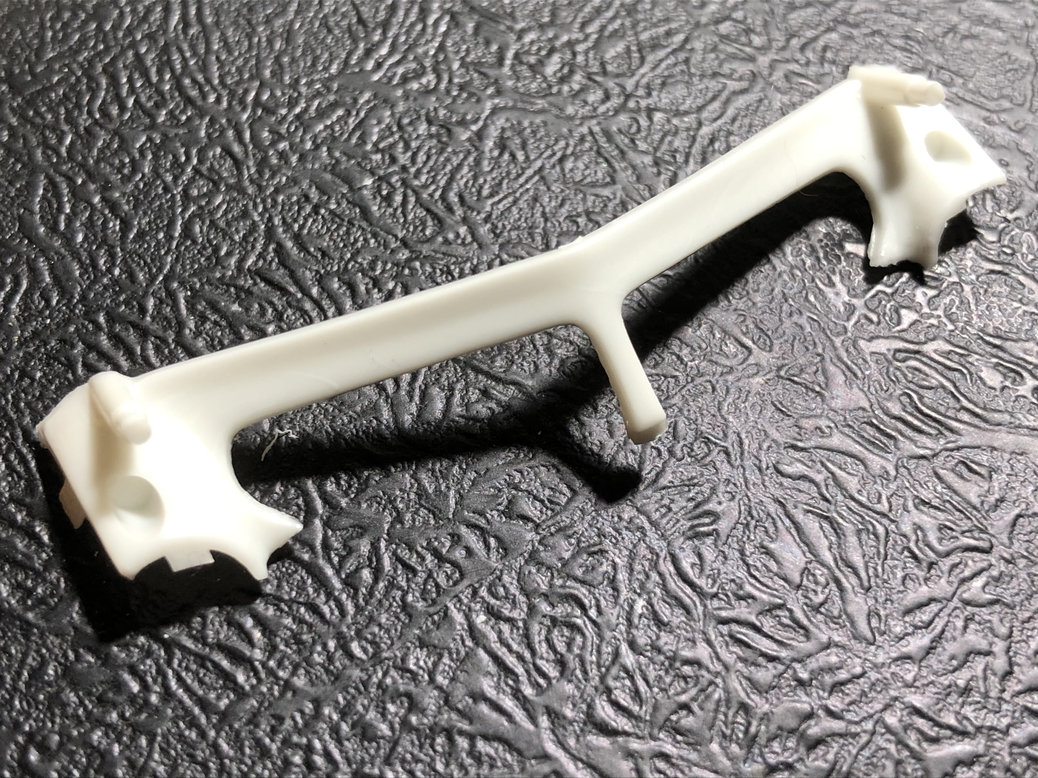
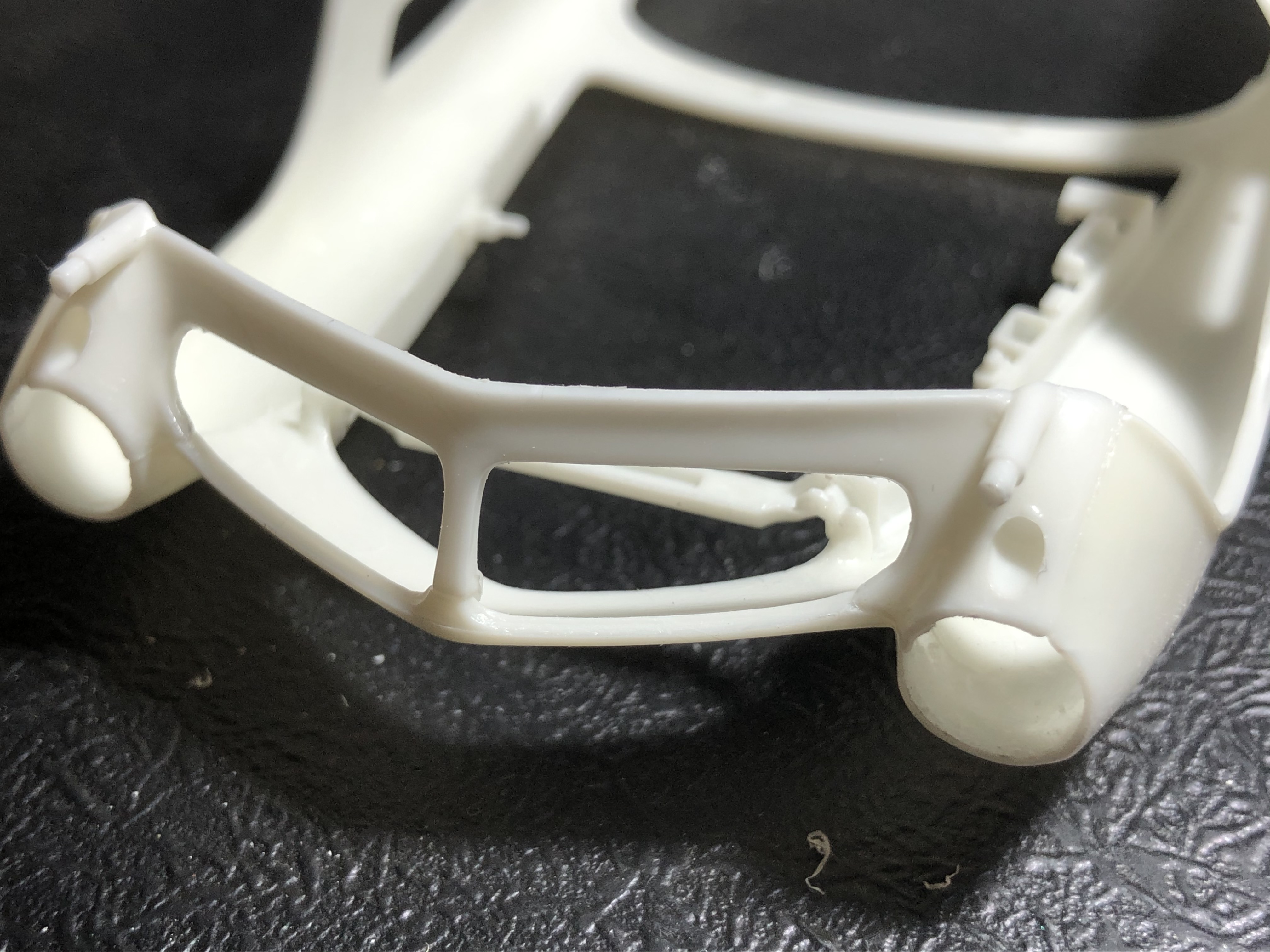
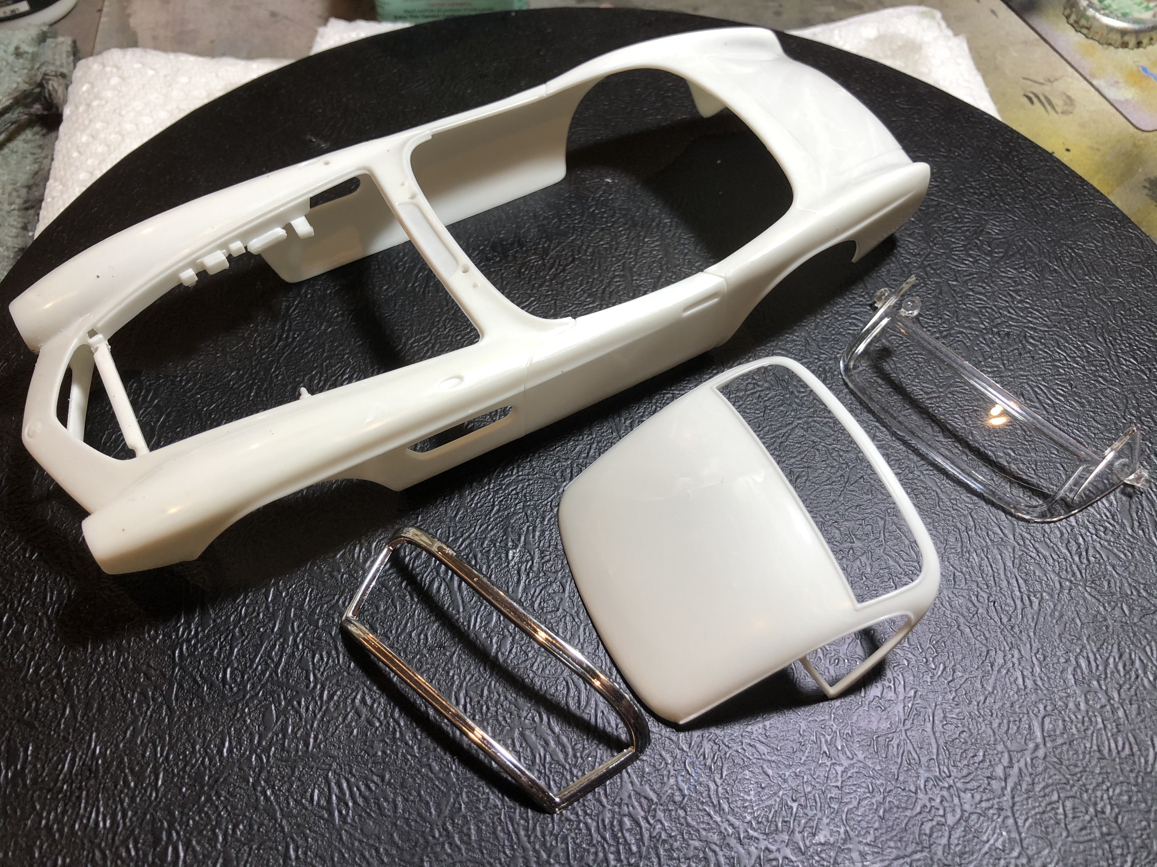
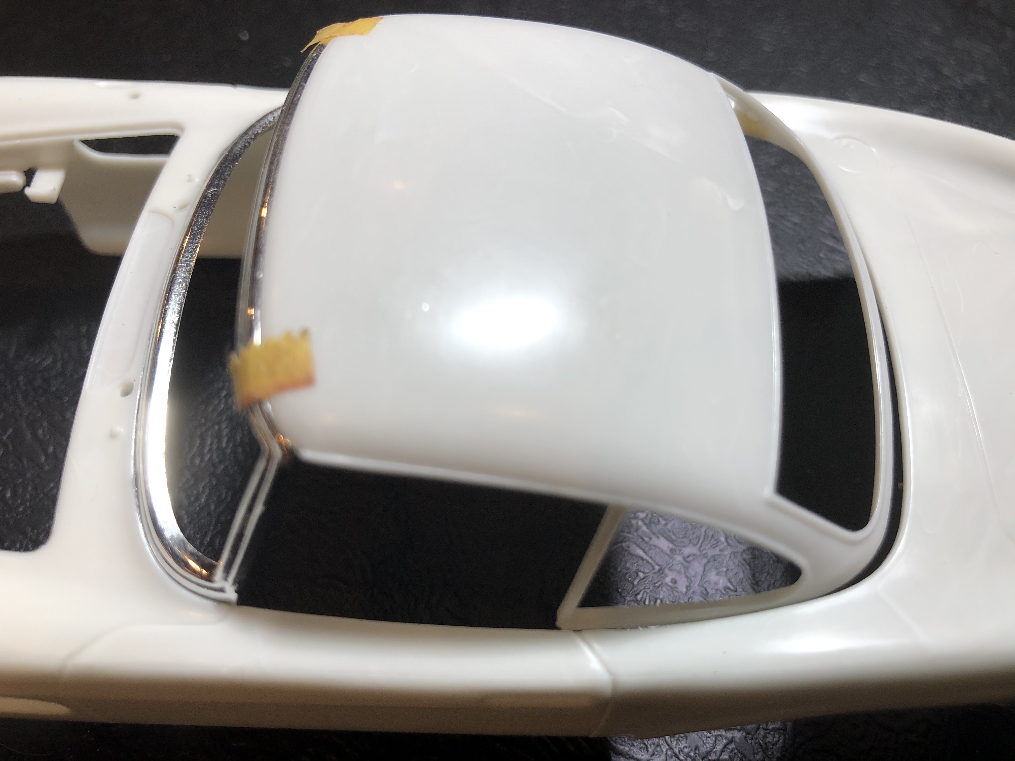
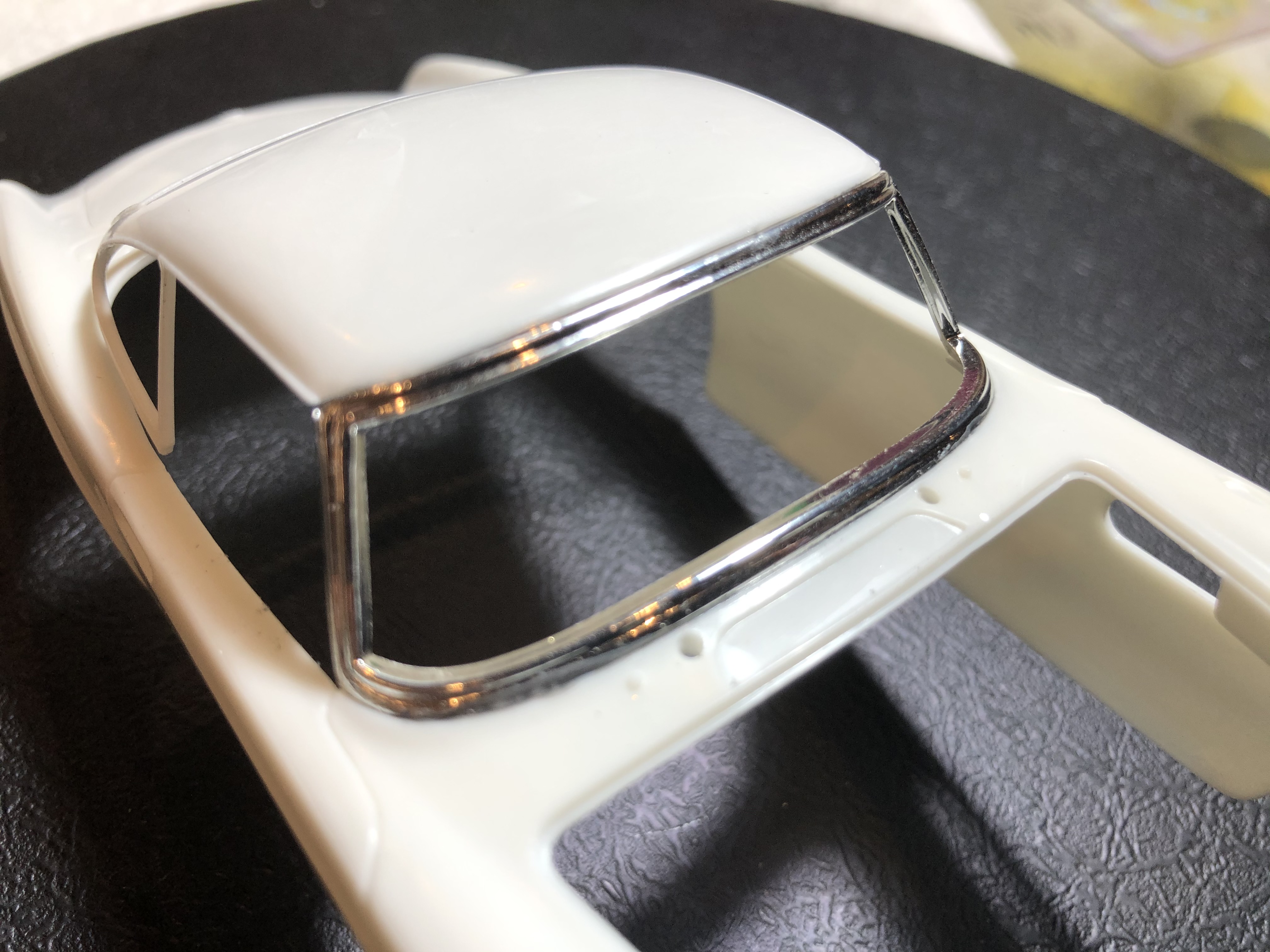
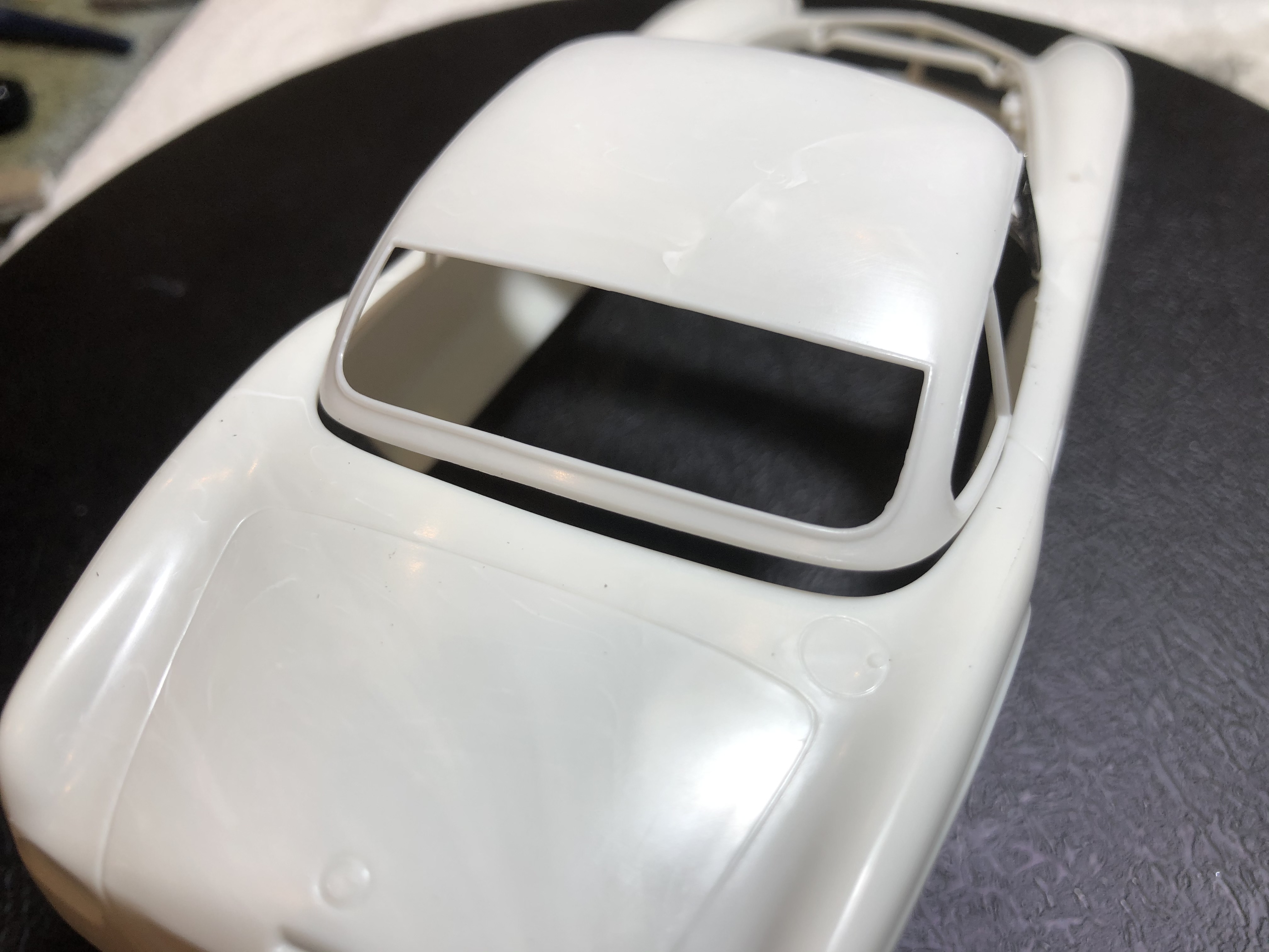
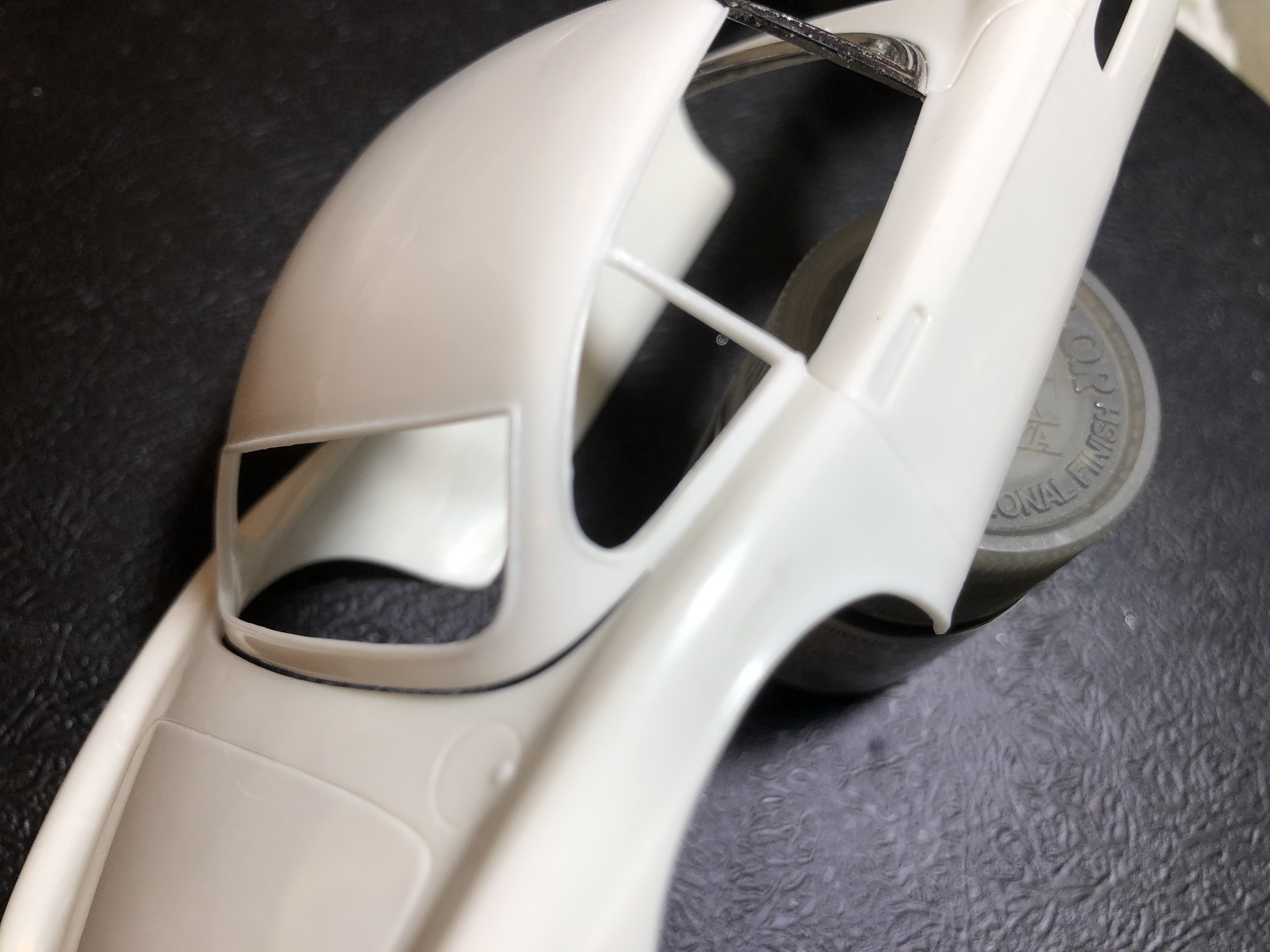
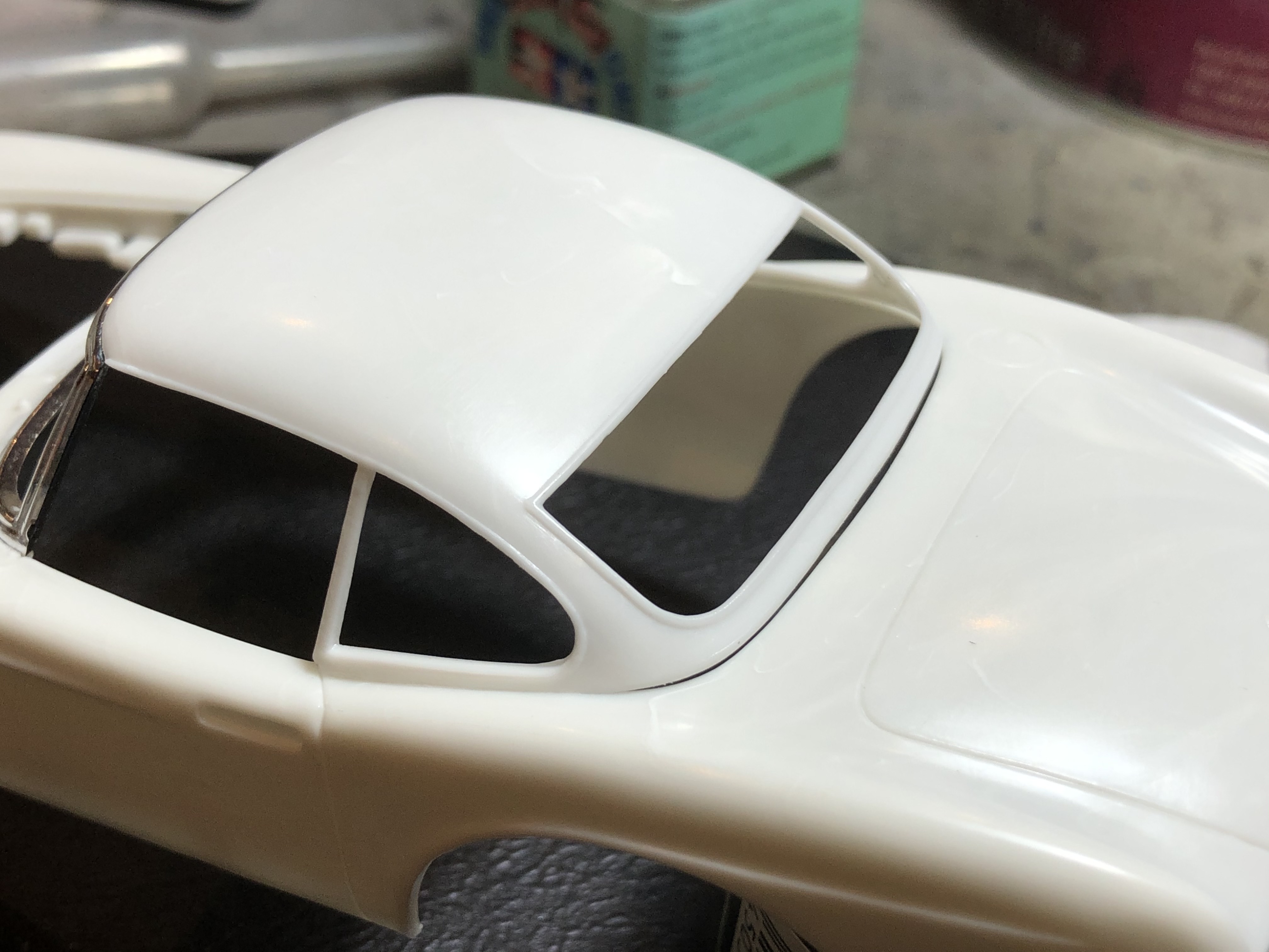
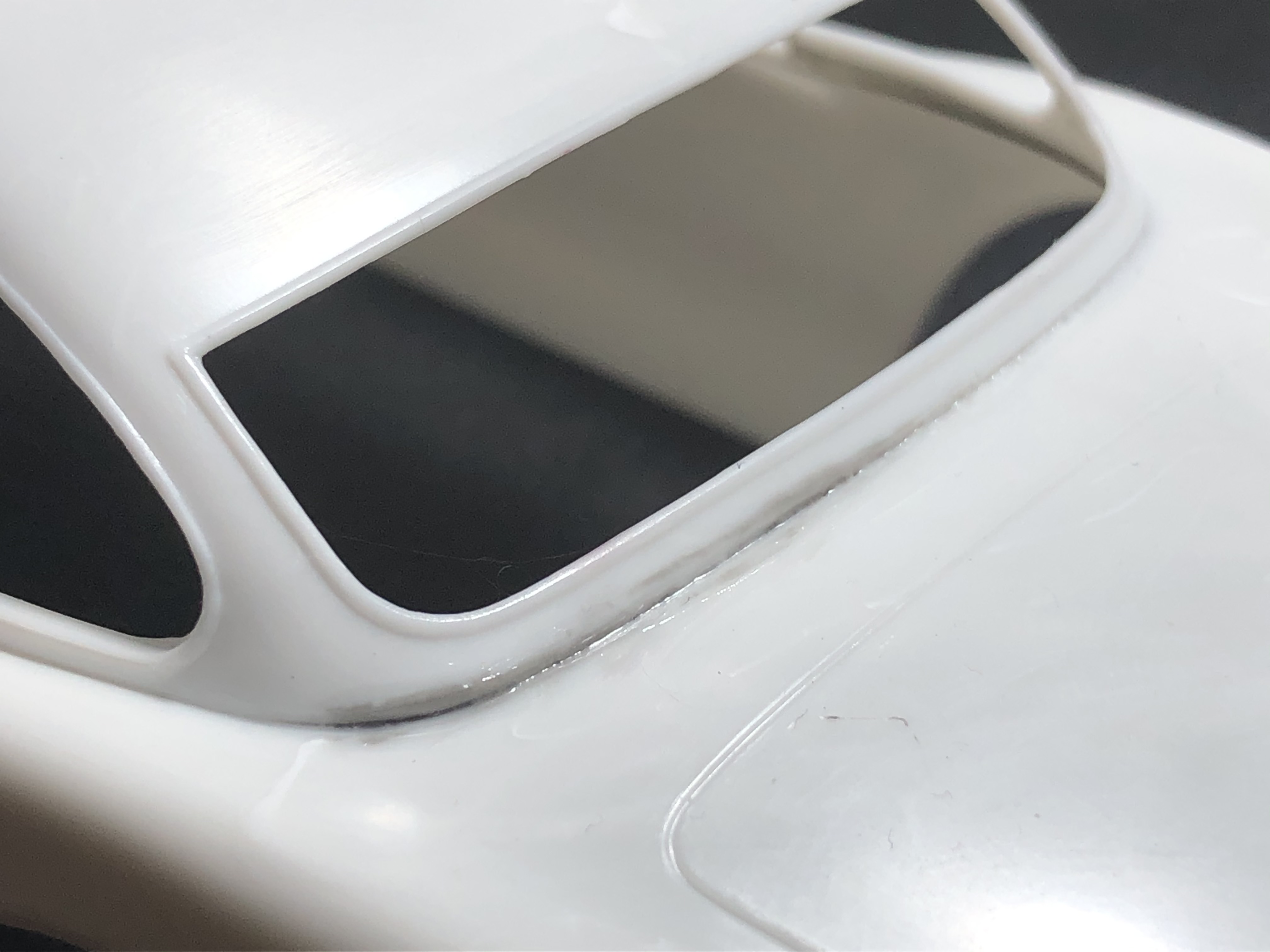
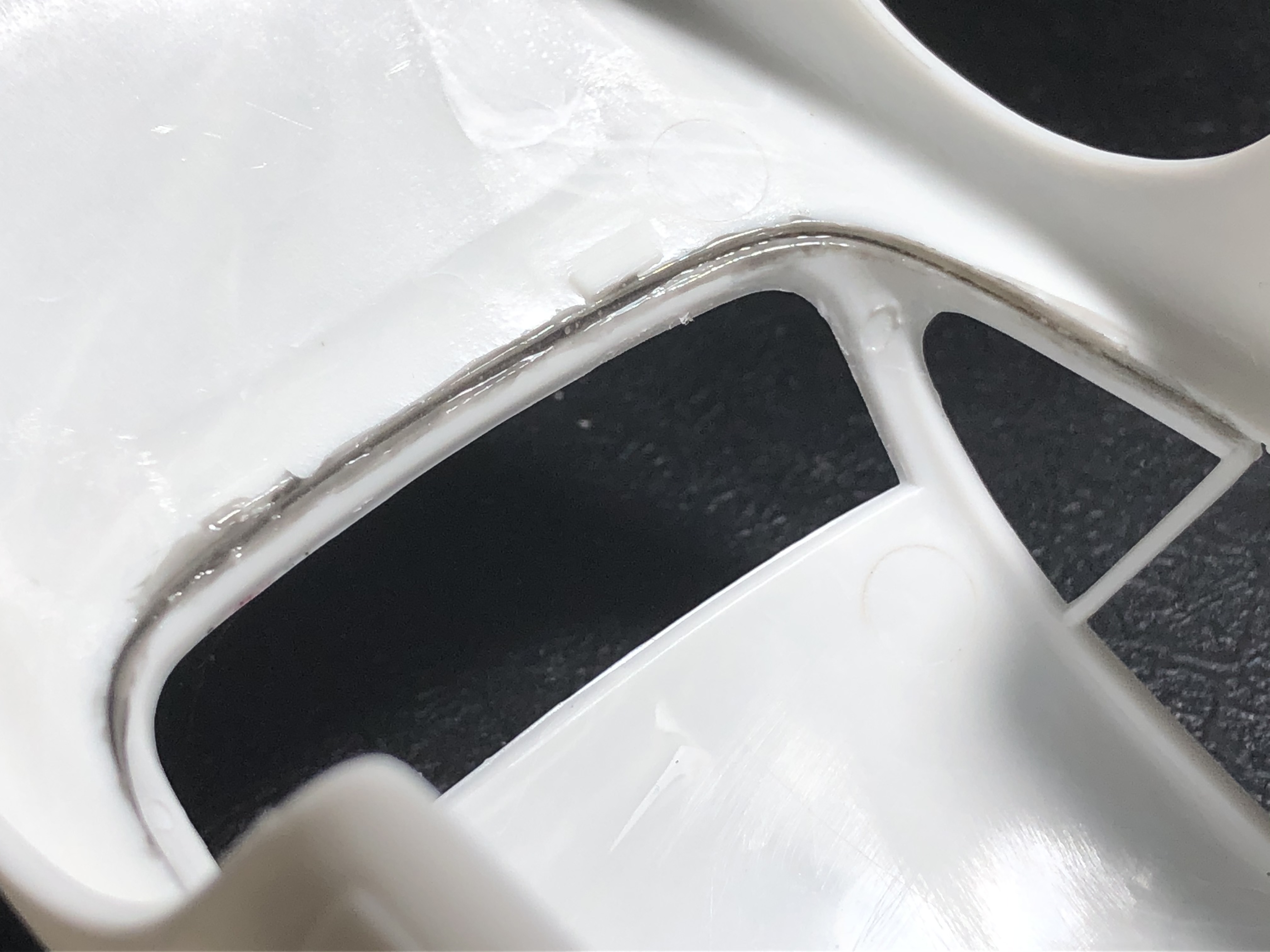
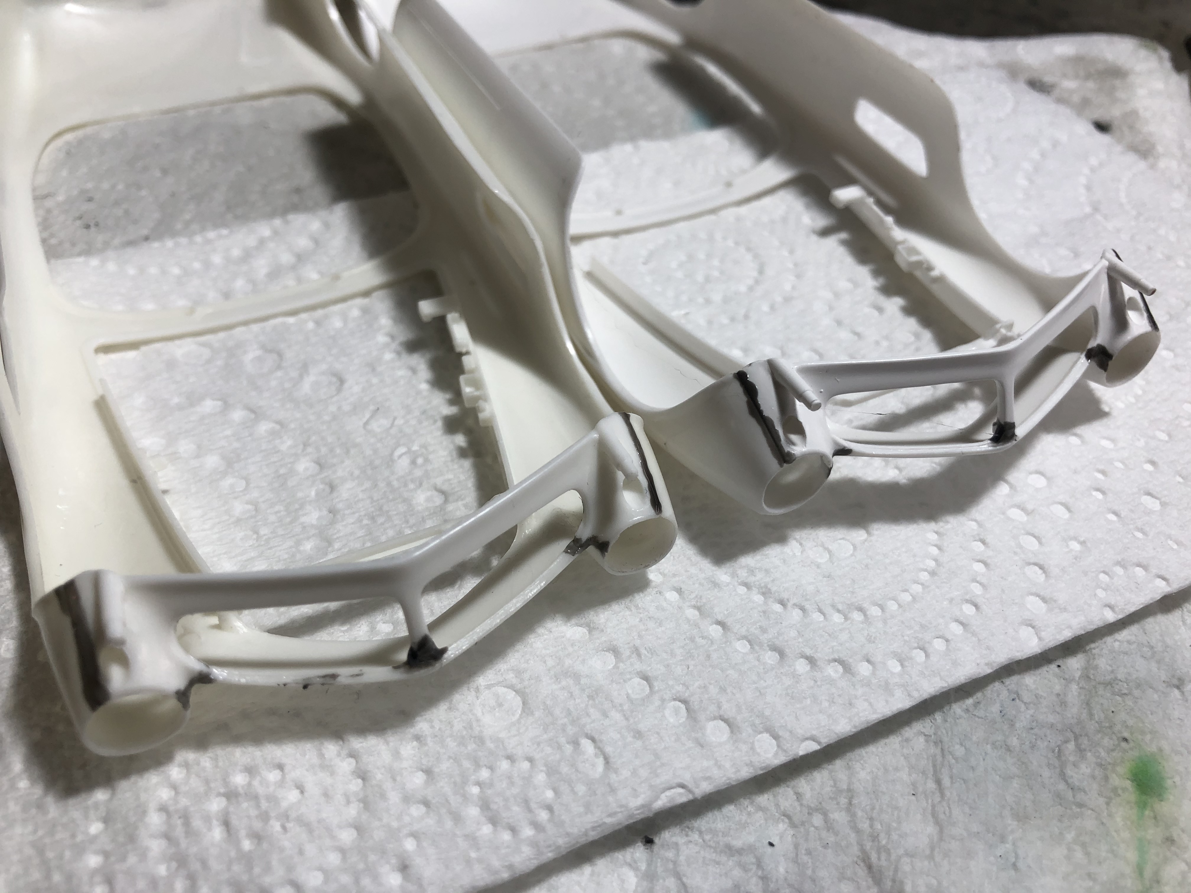
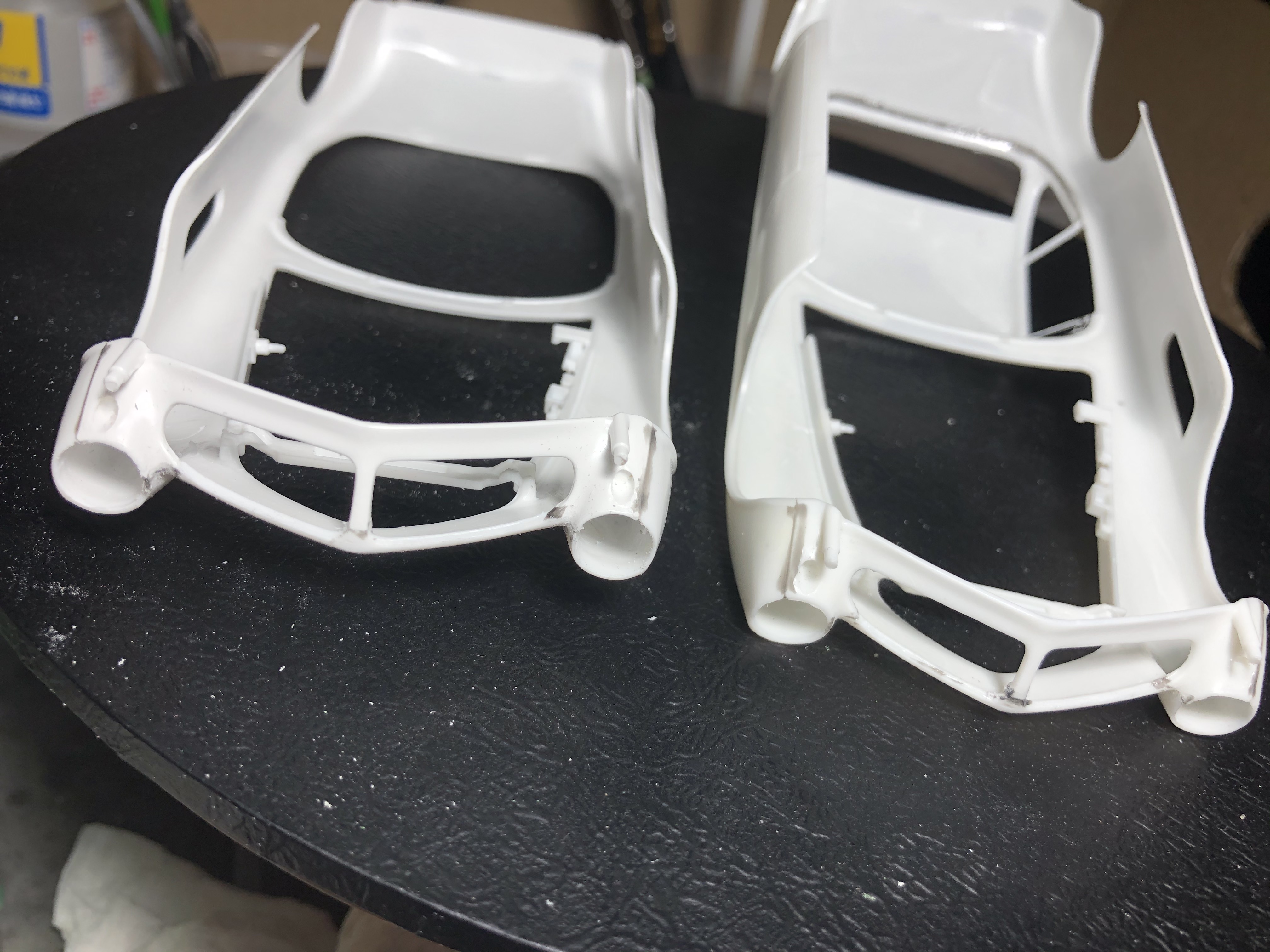
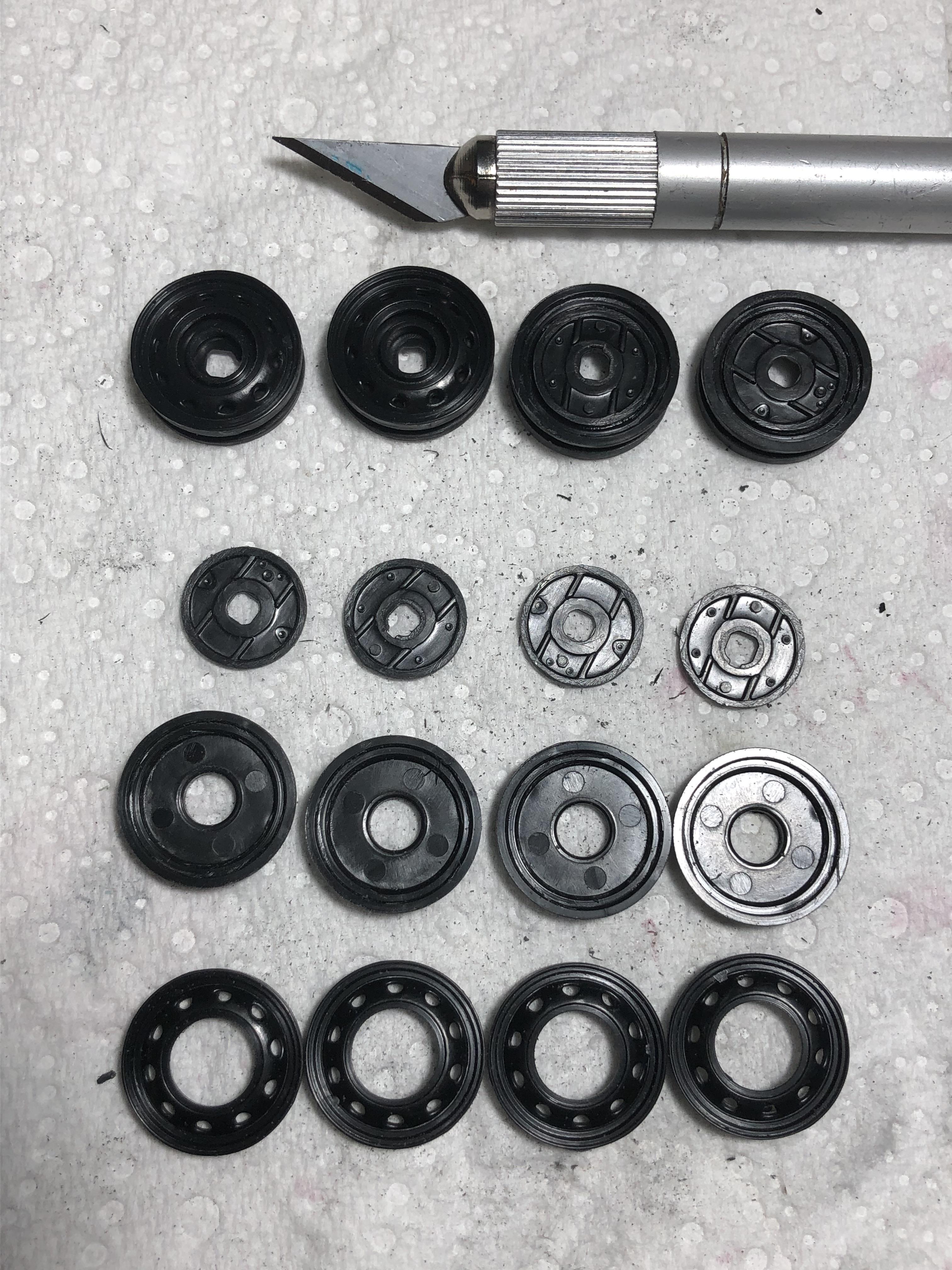
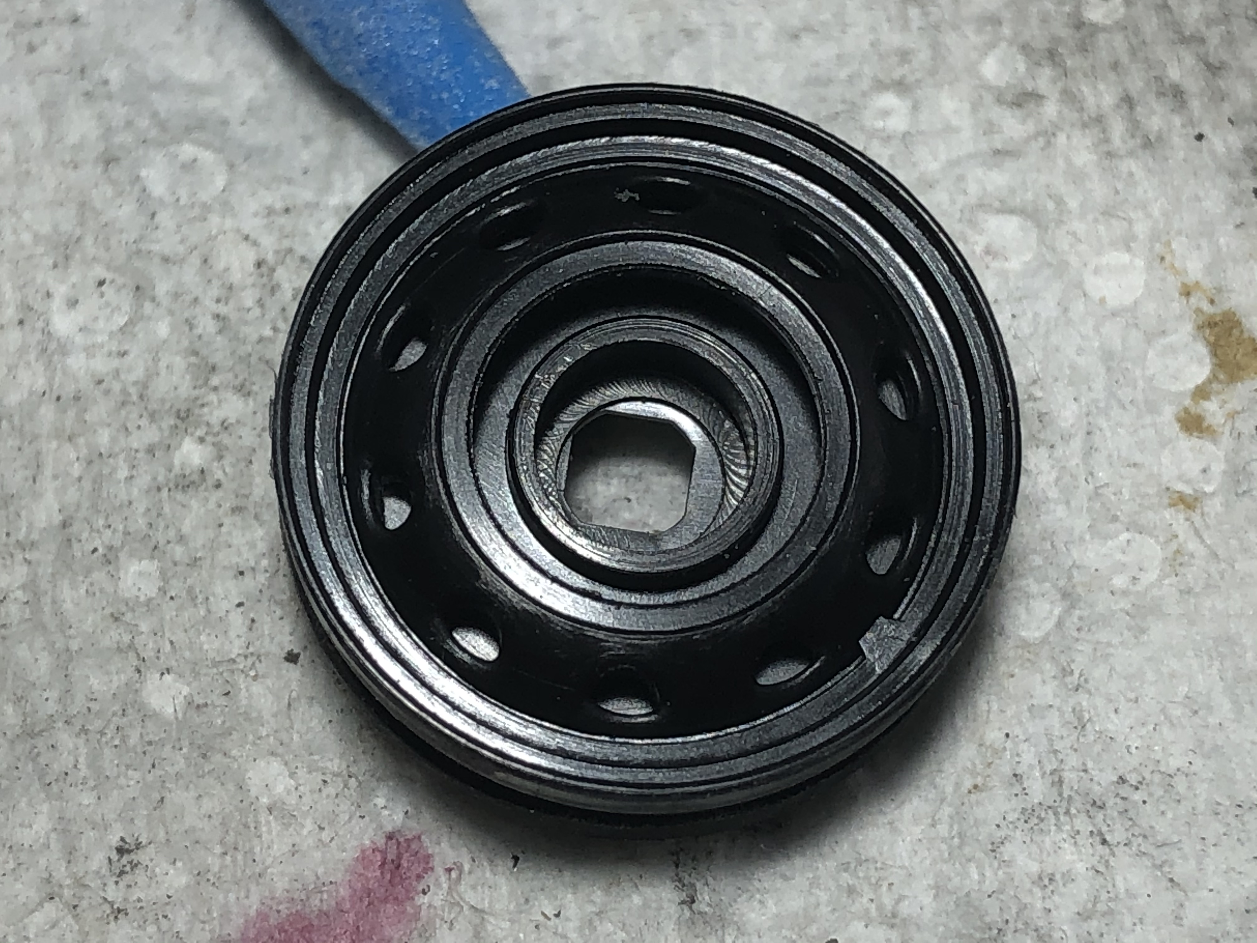
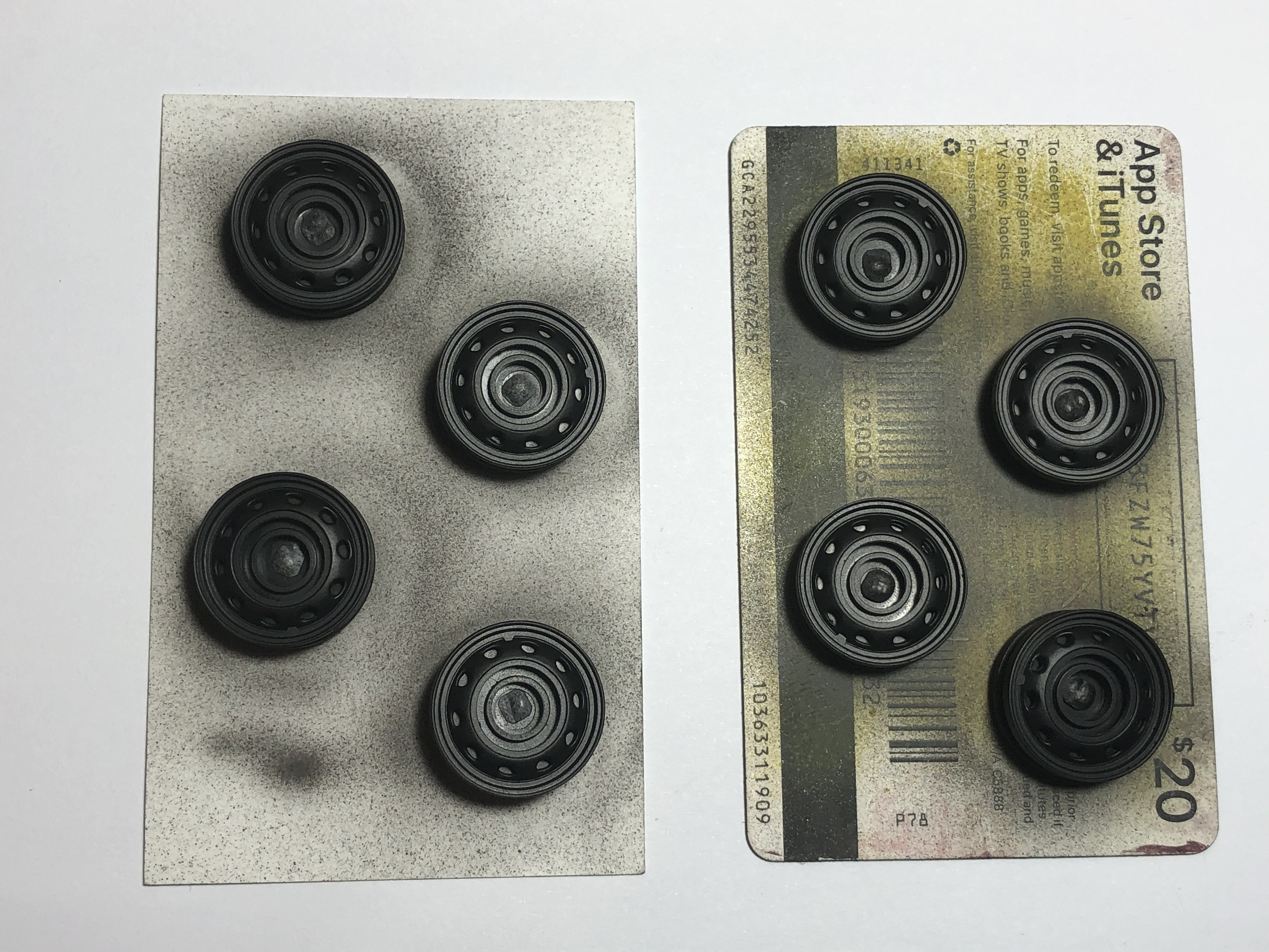
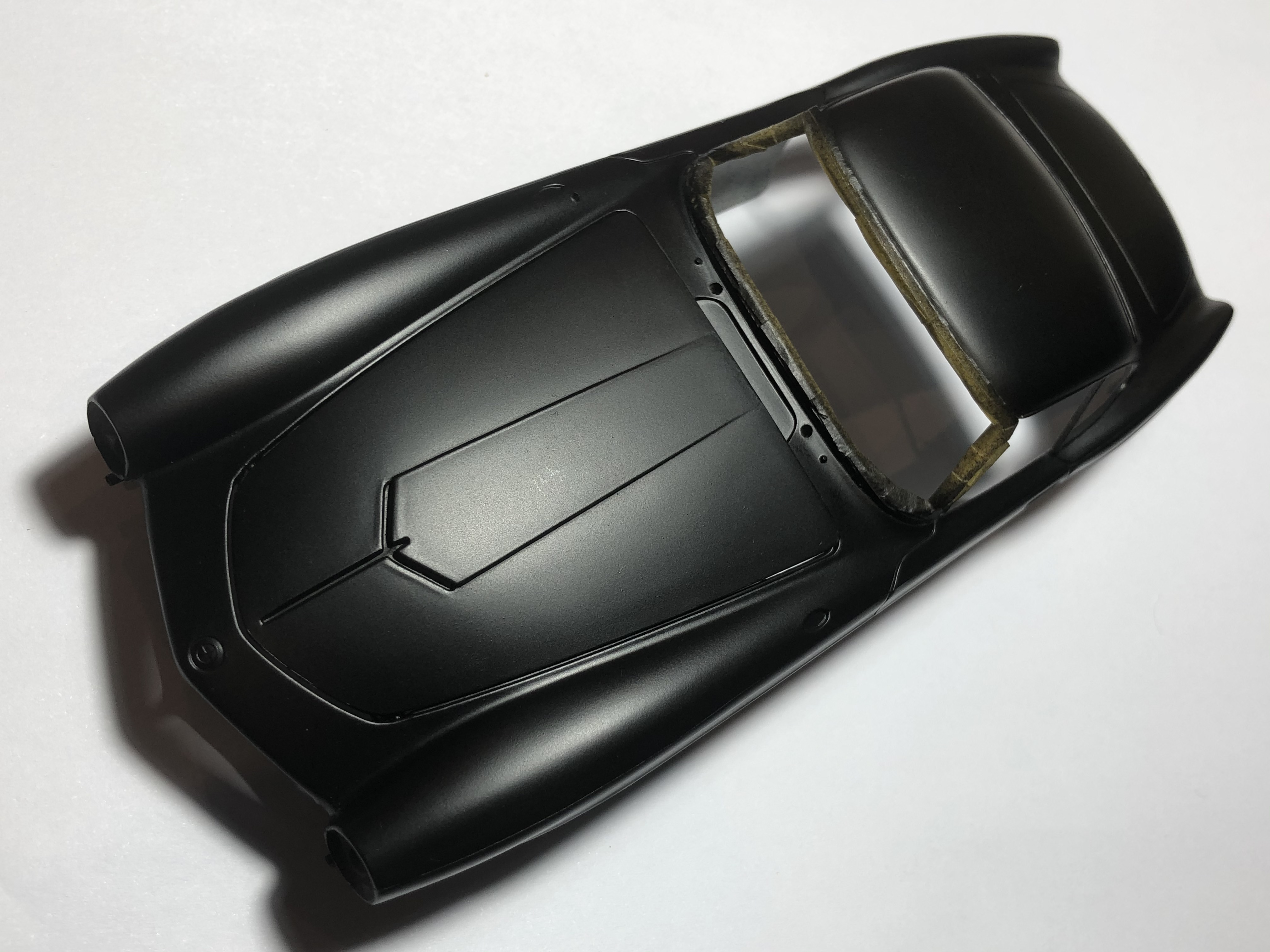
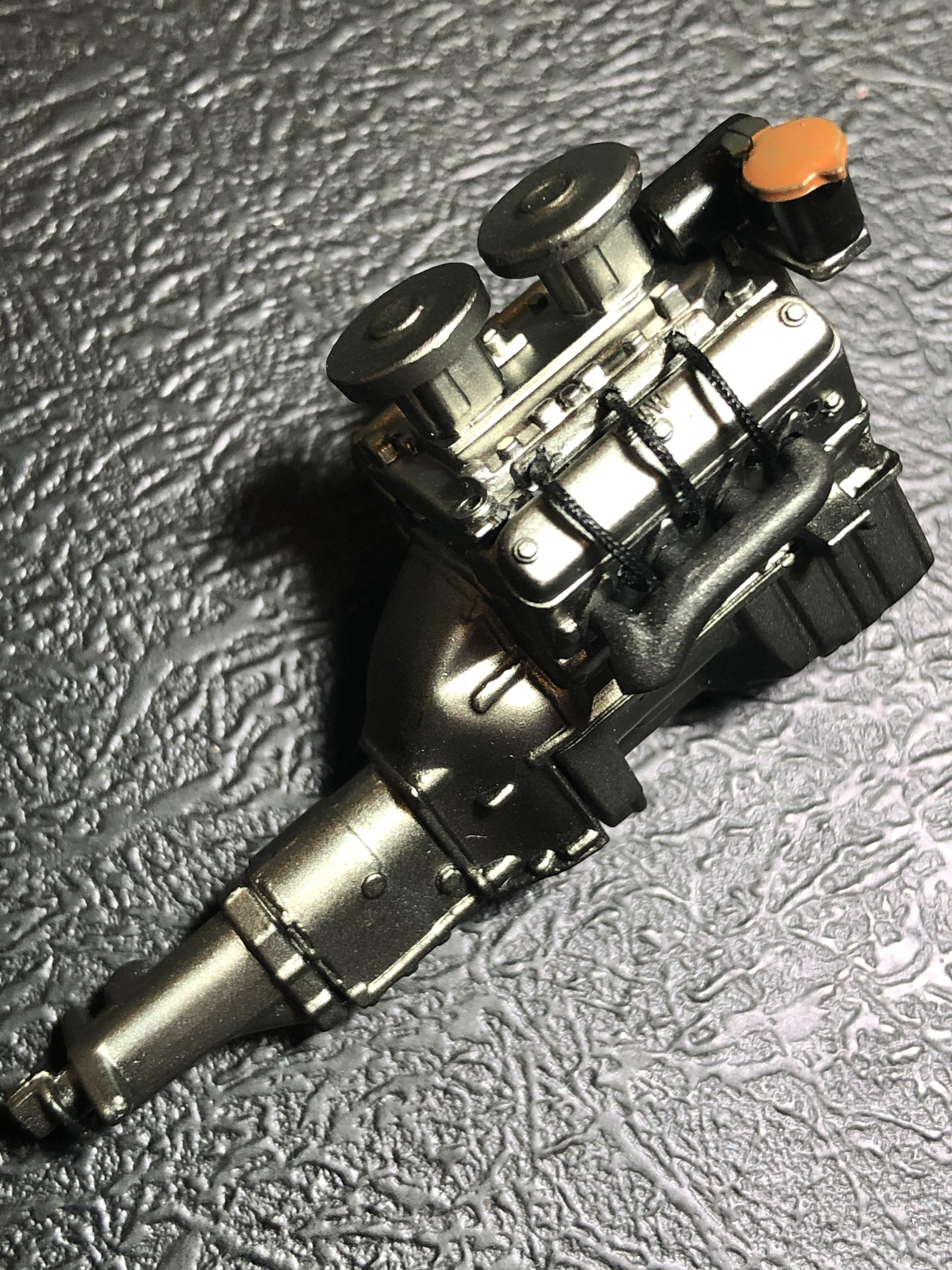
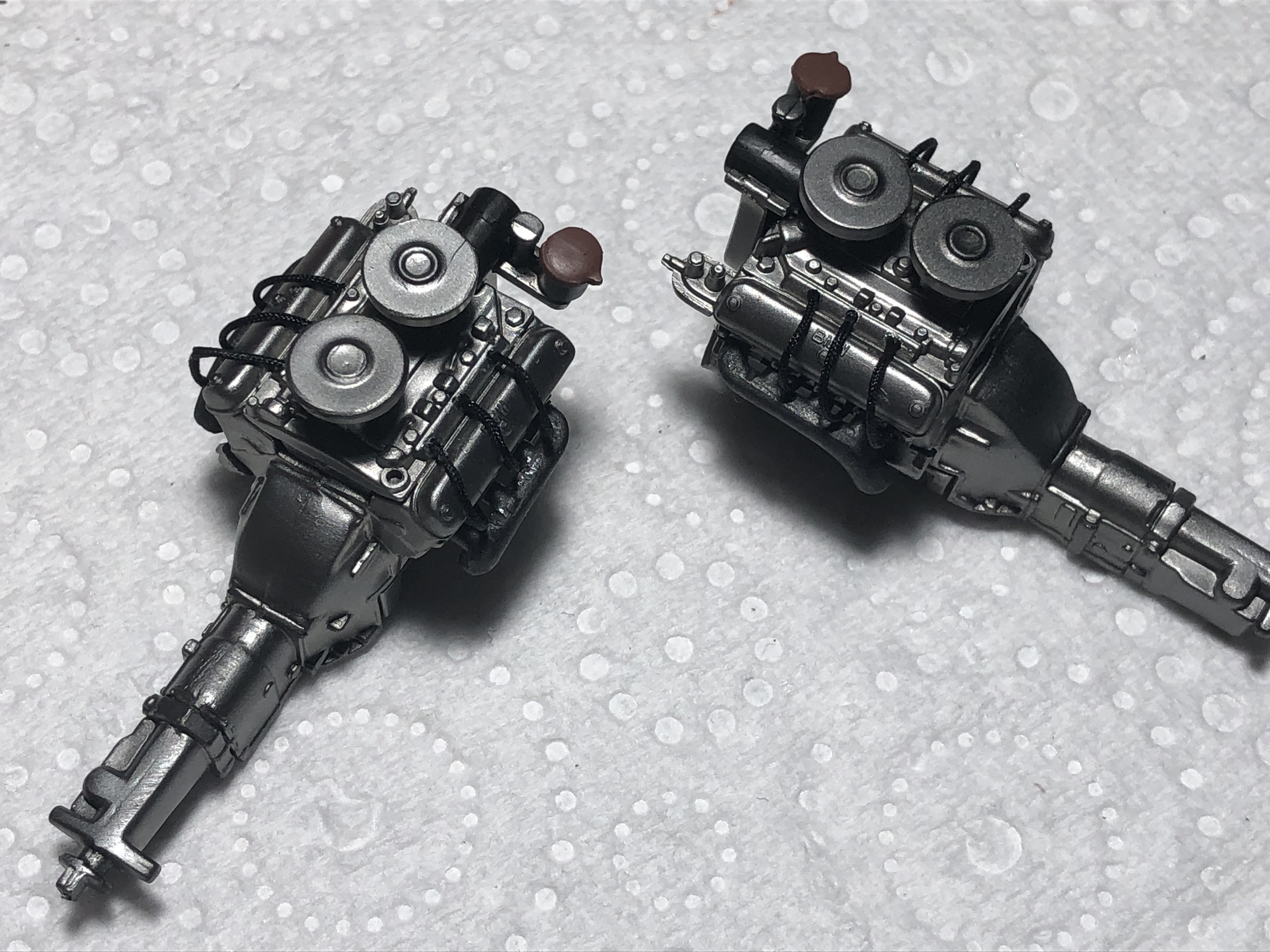
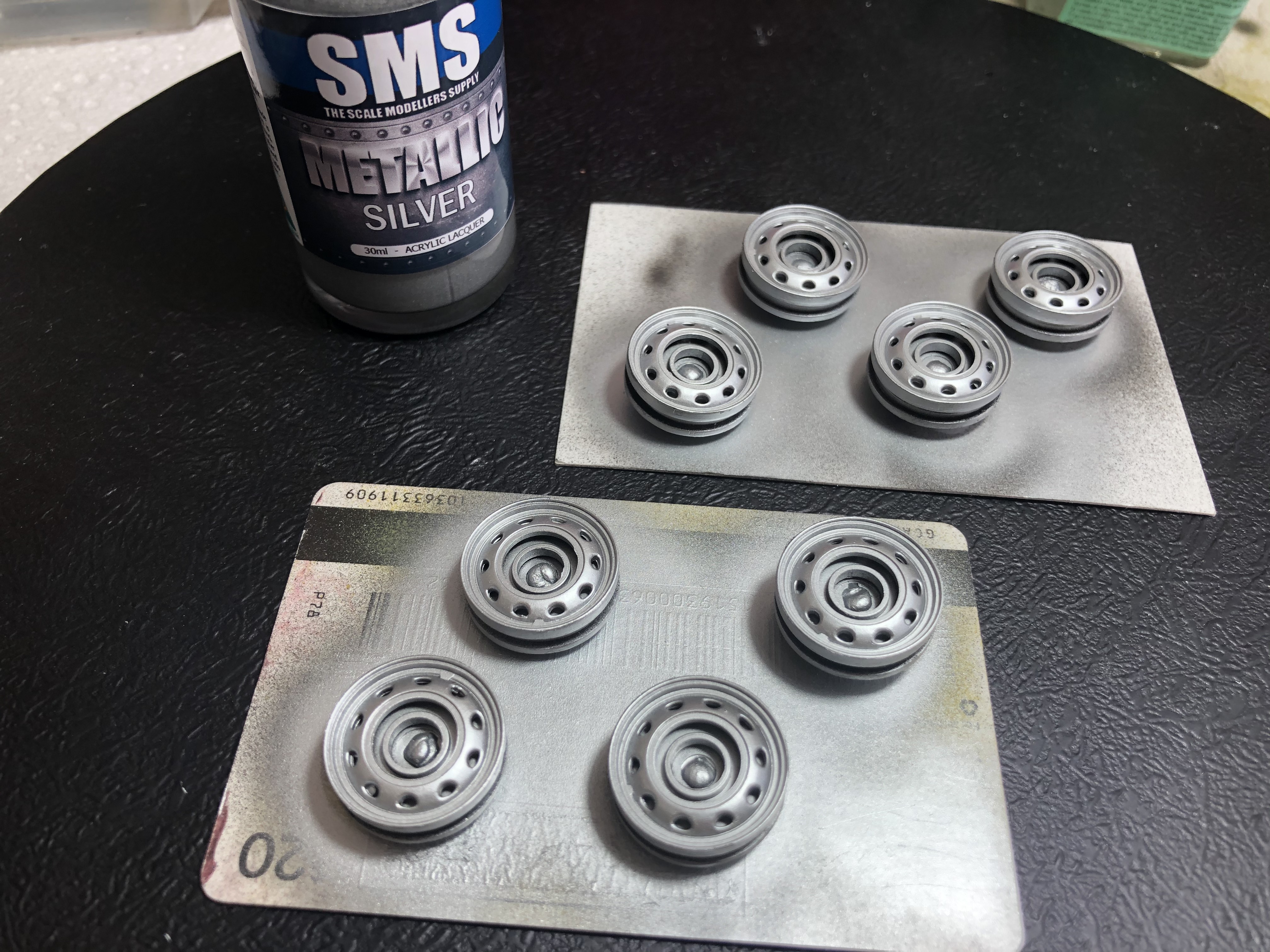
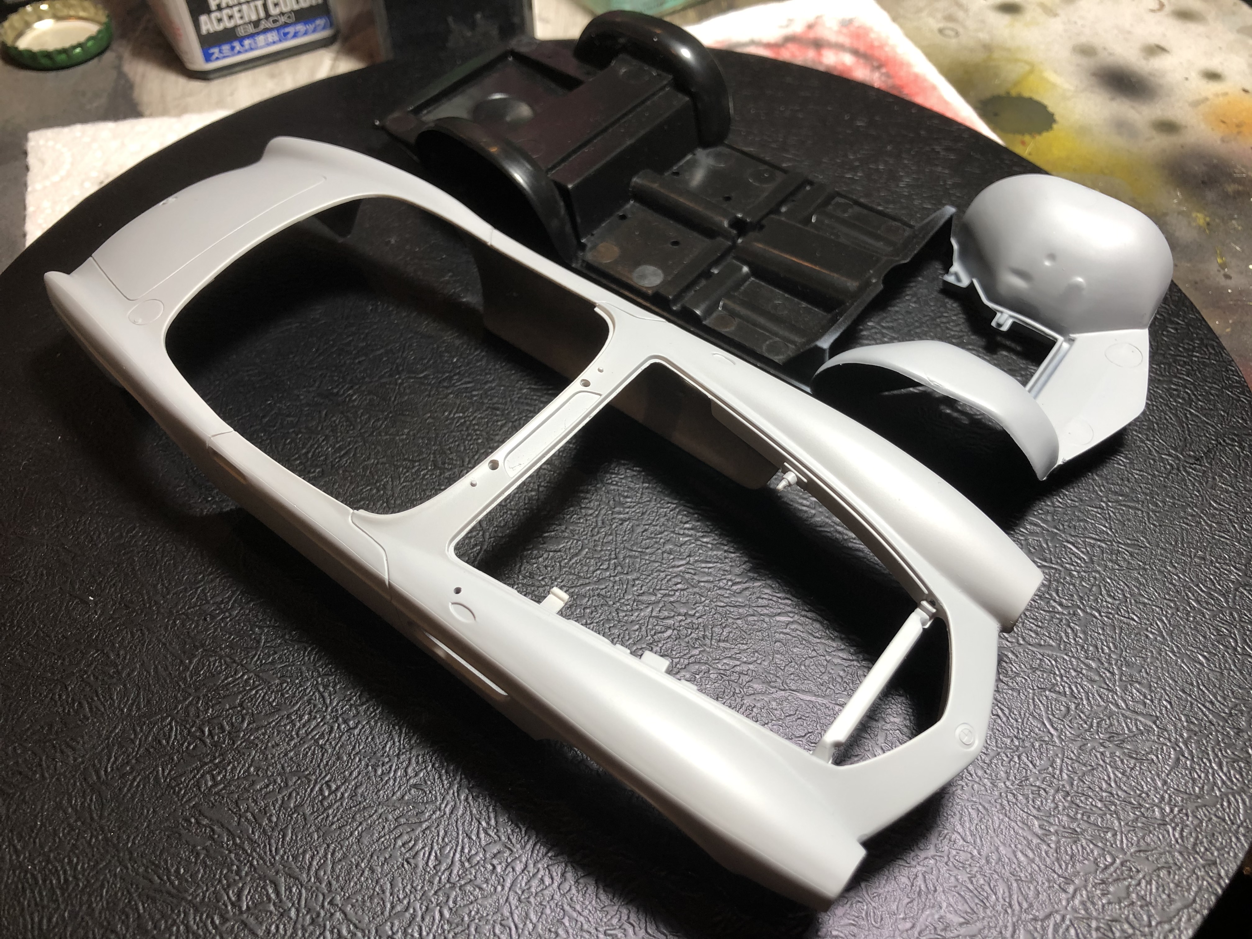
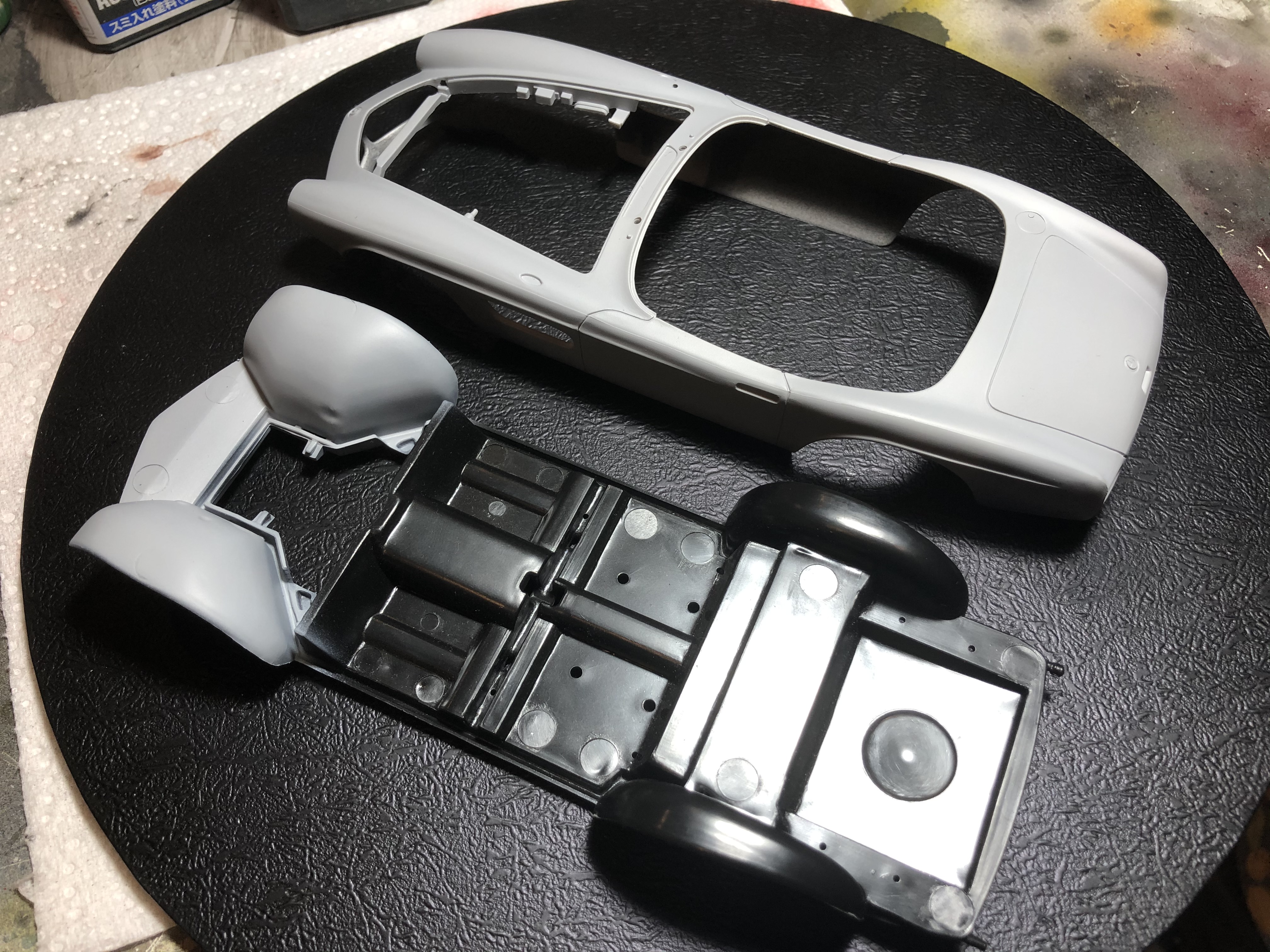
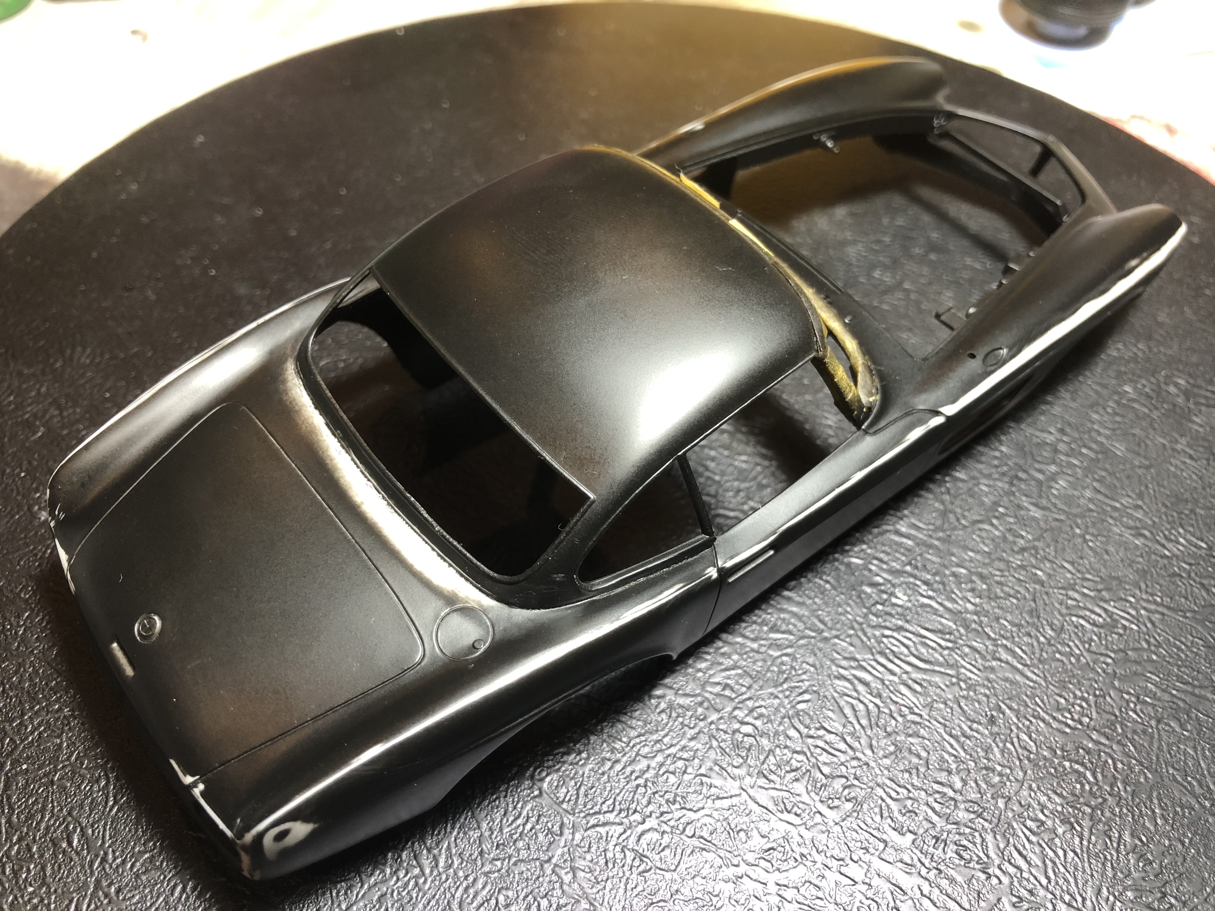
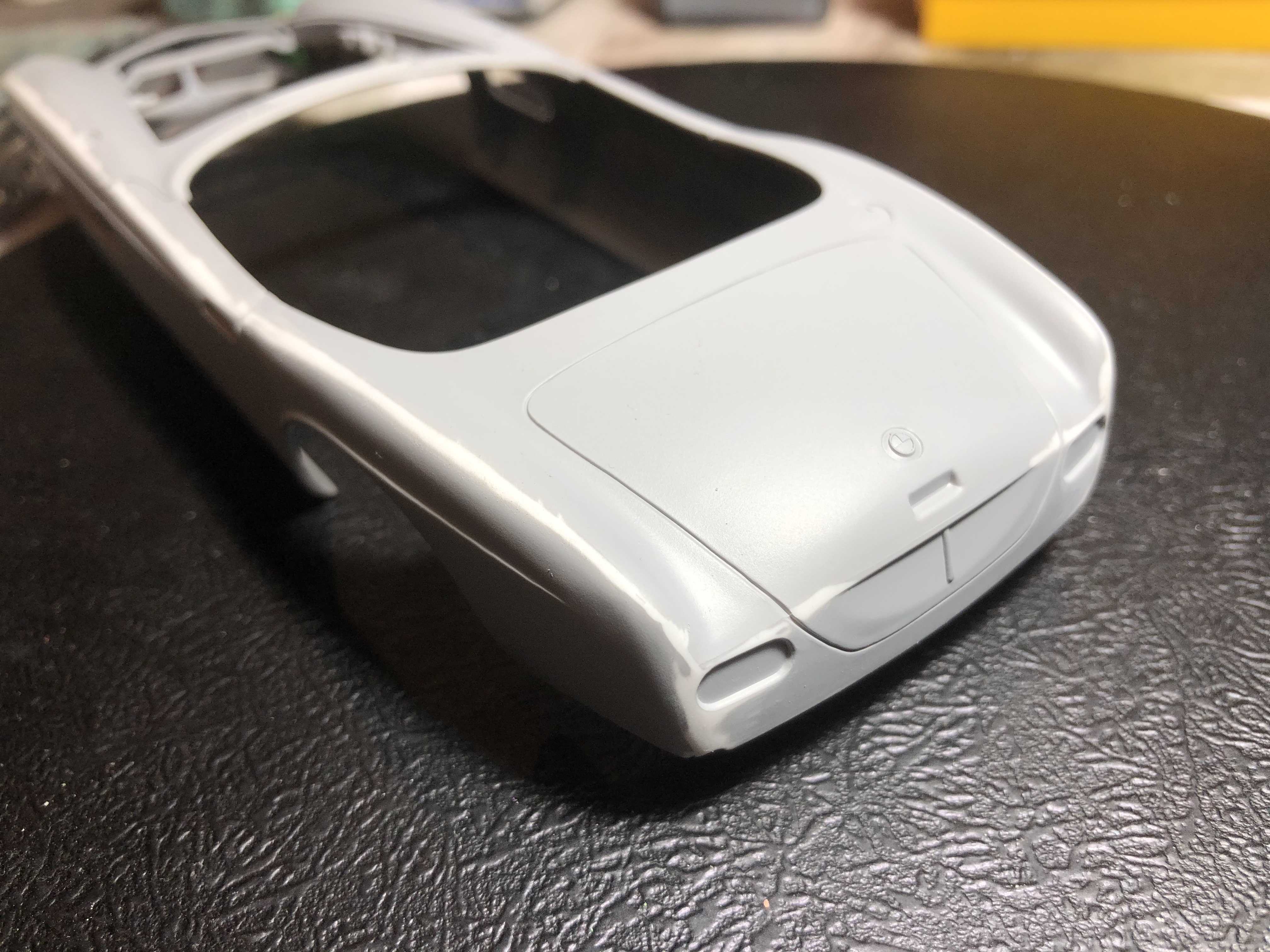
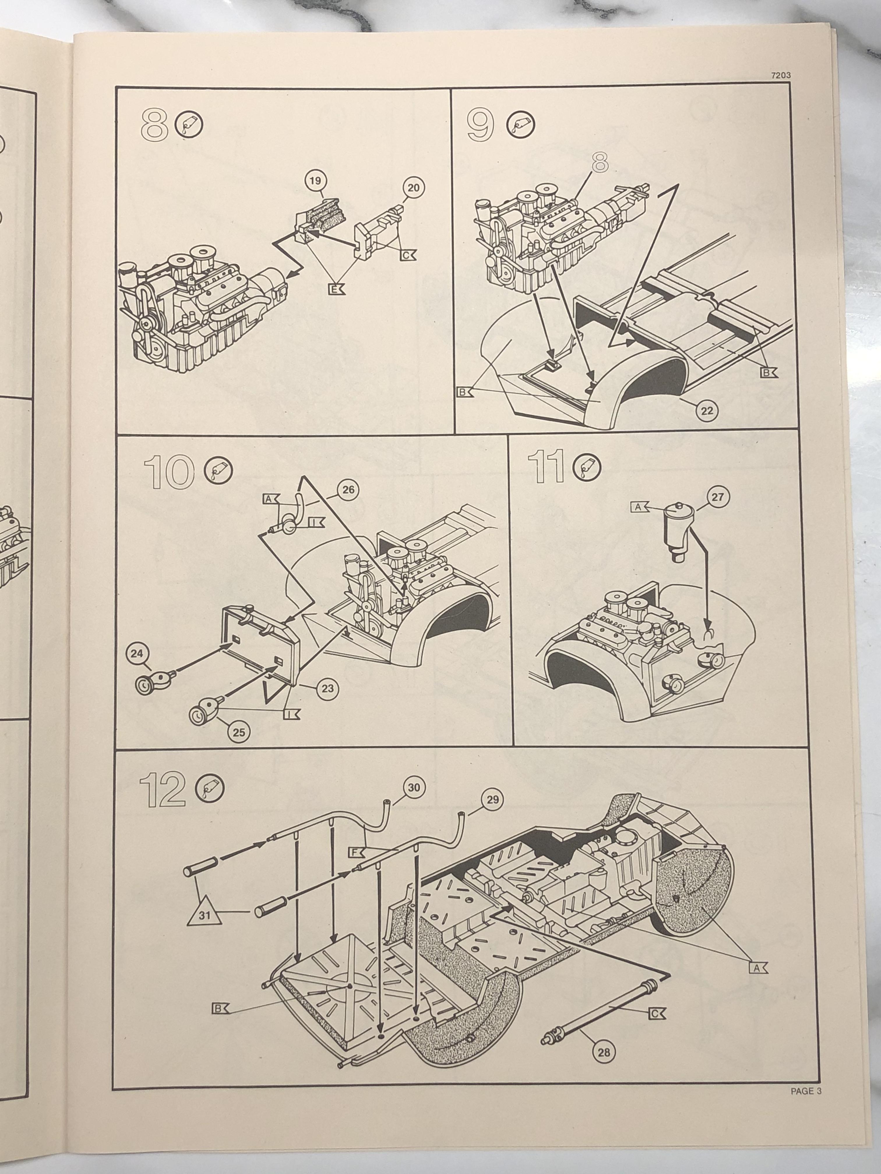
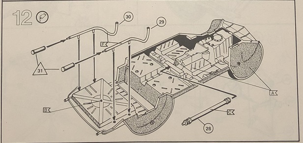
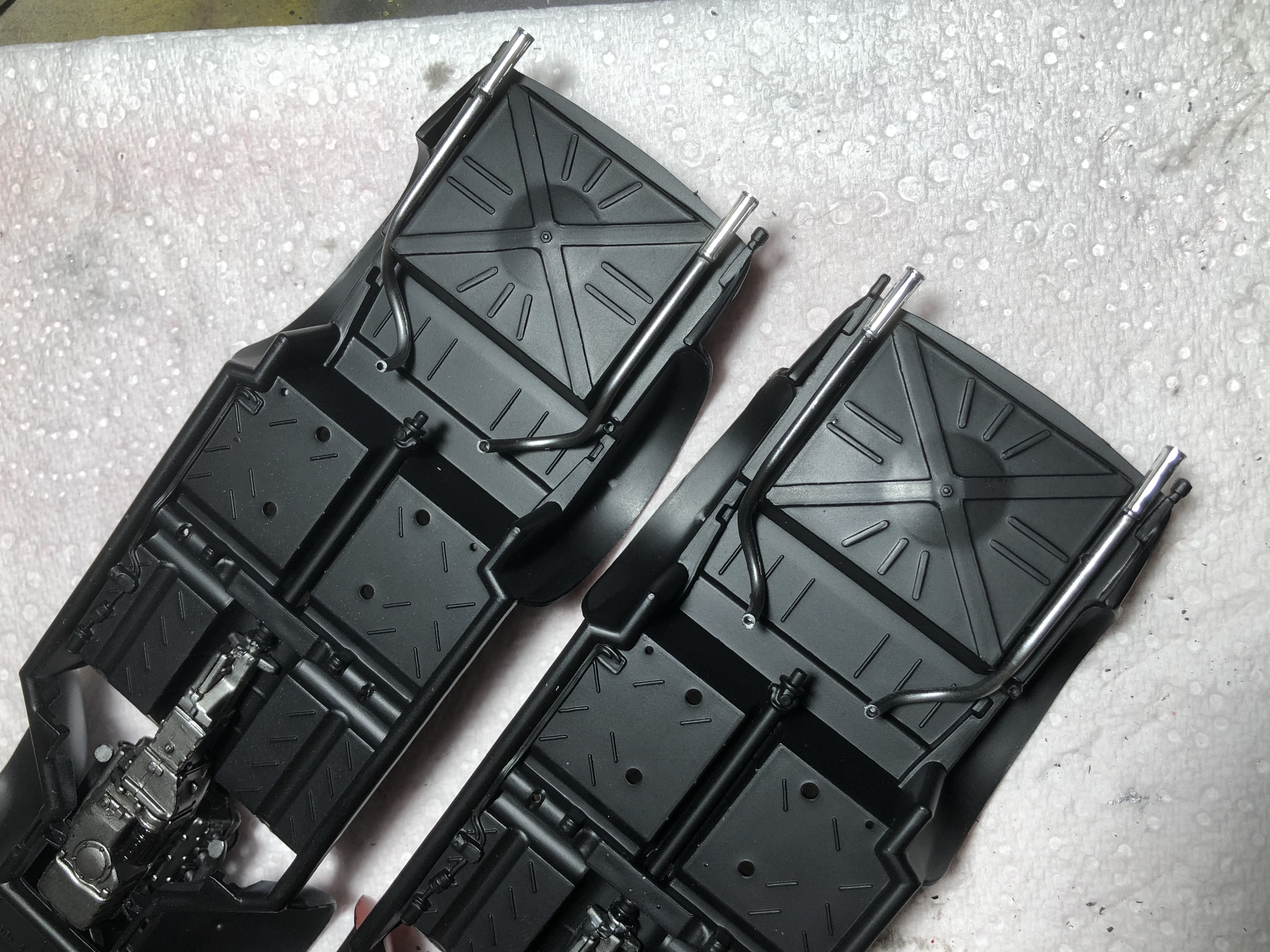
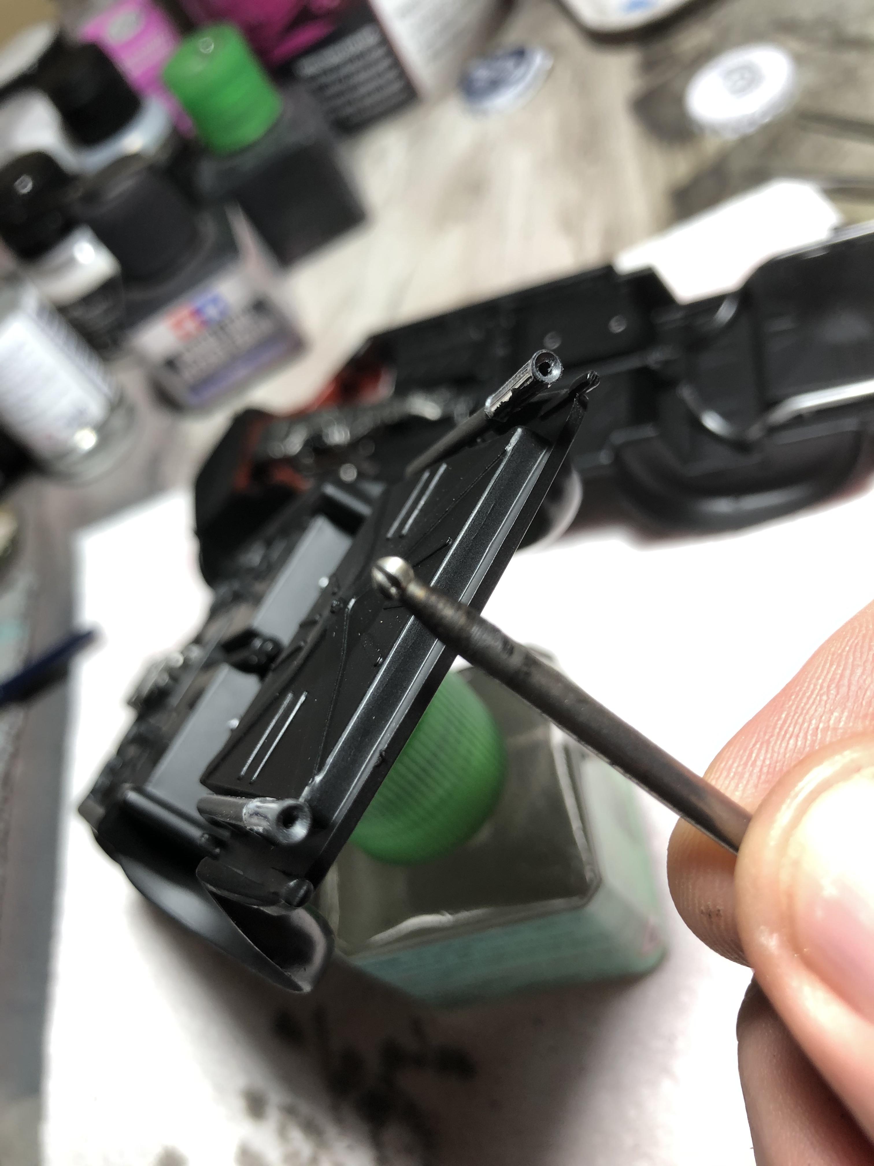
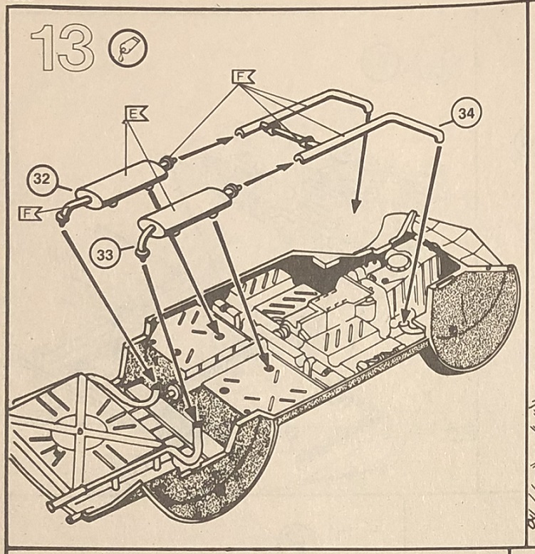
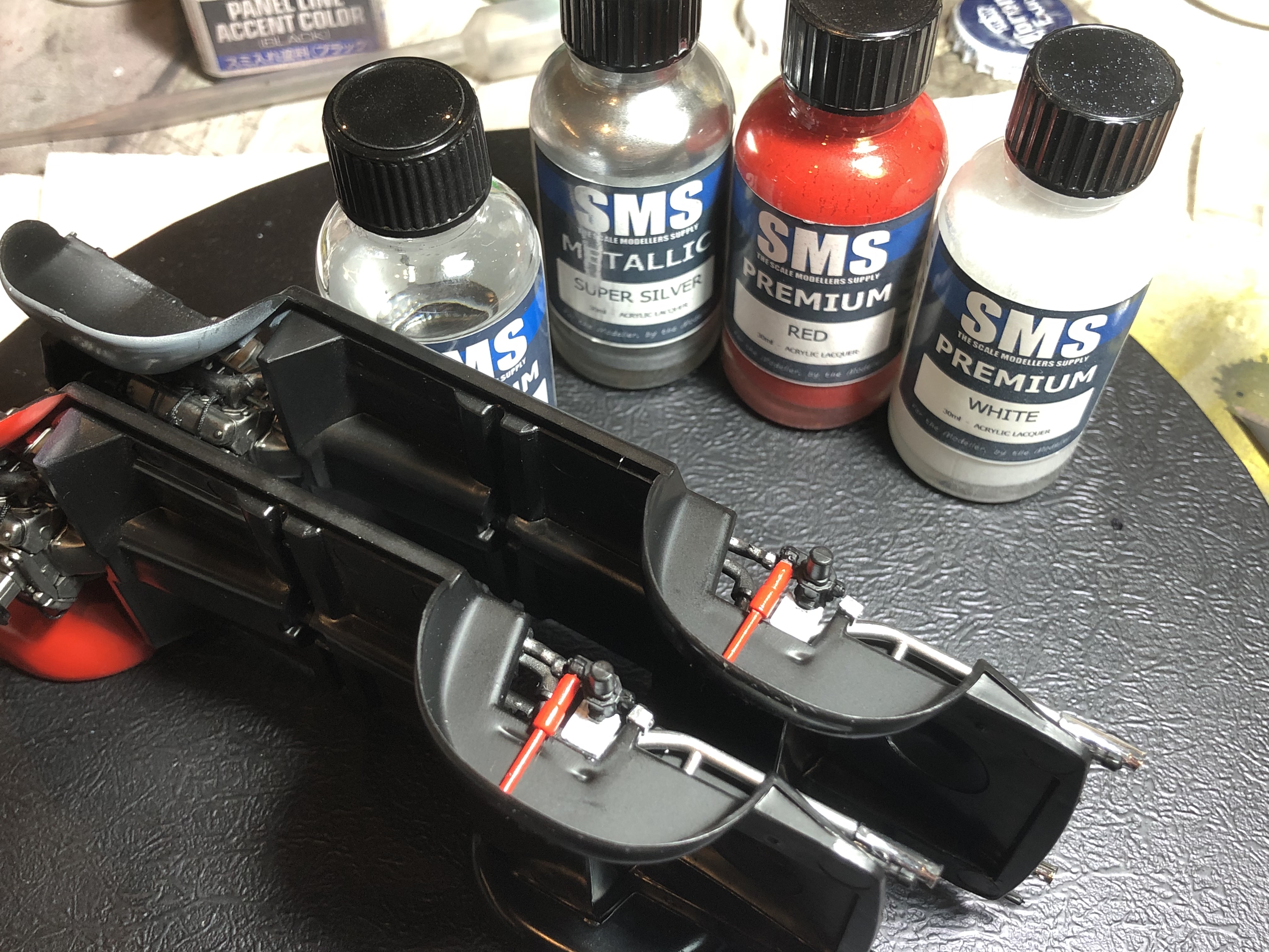
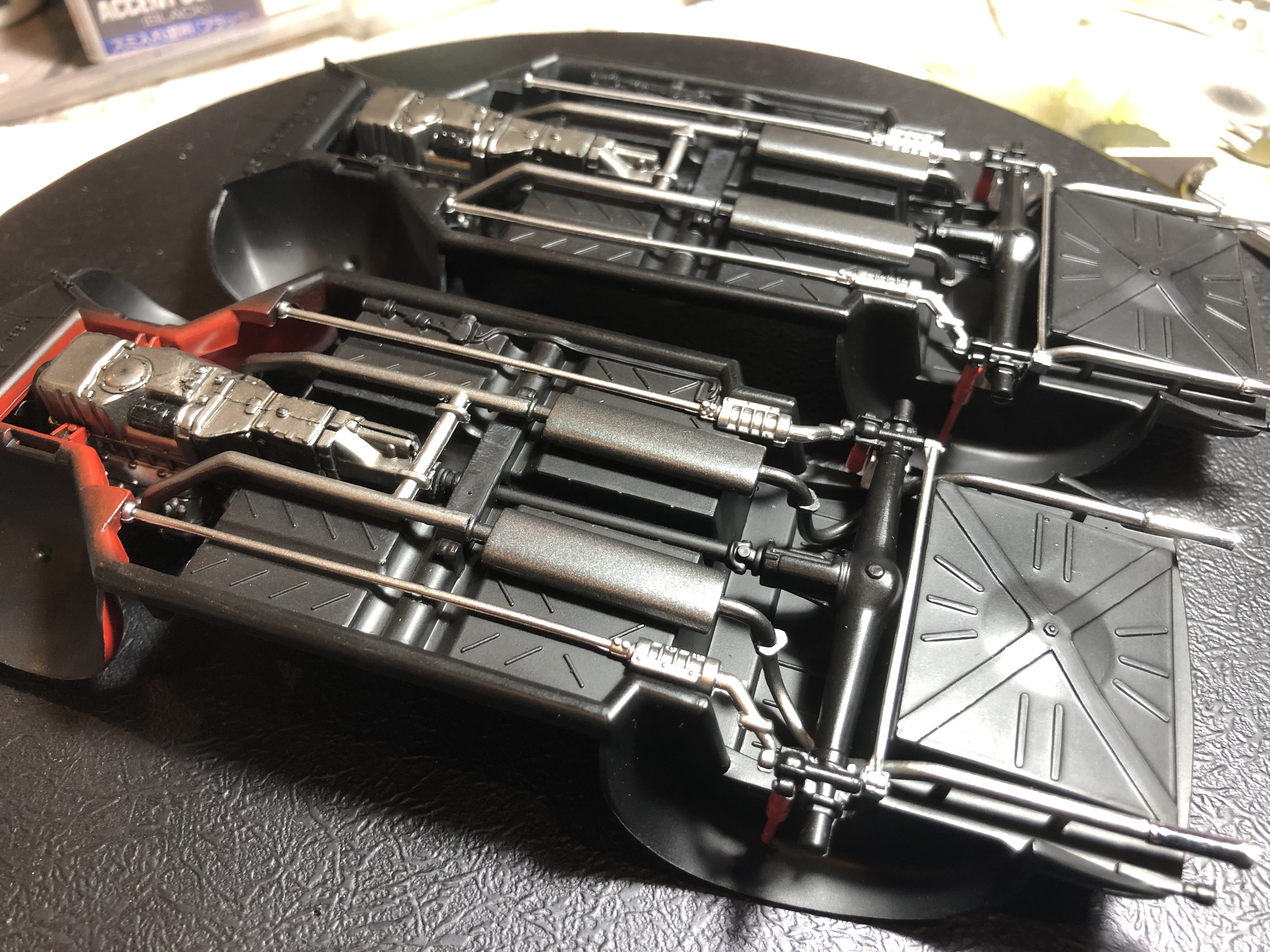
A quick look at the kit parts gives me some confidence, the plastic is nice and clean, very little flash and no sign of deformation. The chrome looks quite clean and consistent, and the window parts thin and clear. I will post up detail shots of the sprues and parts as I go.

I’m very much looking forward to working on these 2 kits, and as always please offer up any comments, advice and constructive critique along the way.

Cheers, D

1 Like

As with virtually all car kits, these start with the engine assembly.

The first 19 parts fit together with a minimum of effort.


The pulley/belt assembly is dry fitted for alignment while the cement cures.

The pulley/belt assembly, fan and exhaust headers will be painted separately and added later.

Of course, the whole process was completed twice!

Reference images for both vehicles will assist greatly in the paint and detailing process.


In terms of fine detail and accuracy, it is great to see that the kits are true to form with the rocker covers rounded at the top corners and squared off at the bottom, and even include the “BMW” lettering!


First impressions - excellent!

Cheers, D

2 Likes

August 9 Update -

A relaxing hour or so tonight on the BMW assembly line, working on a couple of sub assemblies.

Curiously, there is a big difference in the white plastic between the Coupe and Cabrio kits.
The Coupe is the traditional glossy/soapy Revell plastic, but he Cabrio is much paler satin finish and has an almost chalky feel to it. It might not show up too well in the image, Coupe on the left, Cabrio on the right.

Indeed they are!

I’ve never tried it myself, but I have seen guys getting photos of faded leather or fabric from the interwebs, printing on thin paper and laminating them onto seats.

I have a cunning plan! Coupe to the left of me, Cabrio to the right, white stuck in the middle of view! :wink:

Cheers, D

A couple of hours tonight where I jumped forward to steps 35 and 36, starting to get the main body parts prepped for primer. First up is attaching the lower nose and cleaning up the sprue attachment points and a bit of flash (this is the Coupe body).


It lined up and fitted together with no problems. Just a fine join to fill and sand over prior to primer.

Next up is attaching the inner frame to the underside of the bonnet, hood, noisy end lid, whatever you want to call it! :wink:

Once the Coupe was sorted, the Cabrio joined in.


Inching closer to getting some painting done.

Cheers, D

Looks good so far. I’m going to follow this build to see how much I can learn! About the fabric details of the seats and interior, Scale Motorsport offers upholstery decals that may work for you.

https://scalemotorsport.com/collections/upholstery-patterns

Thanks for checking in! I have some of the Scale Motorsport options, very nice products.

Some comments from the old Kitmaker site thread:

Nice work D. The inner frame, for the hood, being a separate part, is a nice touch, from Revell. - Jesper

interesting that inner frame design by BMW - Russell E

These BMWs are looking great. As Jesper said, some nice touches from Revell in there, especially the detail on the engines. Glad to see you heading straight to the end of the instructions for some colour! - Michael (Cosimodo)

Thanks guys, I’m glad you are enjoying the build log! This interaction really is one of my favourite parts of the hobby, especially now with other social interactions so restricted.

I’m thinking that BMW made the bonnet nice and light with a single skin and separate supporting frame underneath.

Cheers, D

AUGUST 14 UPDATE

And so the Revell car kit fun begins!

Getting the bodies prepared for paint, I thought that I would have a look at how the Coupe hard top is installed. According to my research “The body was almost entirely hand-formed of aluminium, and no two models were exactly the same. 11 cars were sold with an optional hand-fabricated removable hardtop. Because of the car-to-car differences, each hardtop fits only the car for which it was made.” (Wiki). Looking at the reference images, the gap between the hard top and body is clearly visible, probably in fact the rubber seal is visble.

So, my original plan was to install the chrome windscreen frame and just leave the hard top sitting loosely on top to be removable for display.

Well, the best laid plans and all that . .

Step 1 - carefully remove a thin strip of chrome plating and cement windscreen frame in place - accomplished!

Step 2 - loosely fit hard top to test if fit is adequate to achieve plan - NOT @#$%*&% LIKELY

Step 3 - pour a nice big glass of Shiraz and contemplate - accomplished!

Step 4 - new plan, carefully remove another thin strip of chrome plating and cement hard top in place - accomplished!


Step 5 - repeat Step 3 - accomplished!

Step 6 - Cement side window frames in place and leave overnight to set up properly (tomorrow work on getting the final section in place) - accomplished!


Step 7 - repeat Steps 3 and 5 - accomplished!

Step 8 - off to AutoModeler to report on evenings shenanigans - accomplished!

Cheers, D

D, Impressive work on getting the hardtop to basically fit like it did in the real world. A plastic rubber gasket and you’re home free. - Joel

Excellent work D. Step 3, 5 and 7 have been noted in my little book of tricks - Jesper

That’s some nice shenanigans, D! - Russell E

AUGUST 20 UPDATE

Some more body work accomplished. I managed to get the bottom edge of the Coupe hard top to line up and cement in place, but it’s not an easy task or a neat fit, so I lightly filled and reinforced the join on the top and underside with my black sprue-goo. I lightly applied some more TET to this to smooth it over and get it to wick into the contour of the join, to try to replicate the 1:1 look. Once it’s cured I will give it a fine sand then primer and see how it looks.


I also spent a few minutes cleaning up the joins on the nose assemblies.


Next report should see both bodies in primer. Grey for the Cabrio and Black for the Coupe.

Cheers, D

D,
Now that hardtop really looks like it was meant to fit. I’d certainly say that’s one great job of Rub Goldberg modeling.
- Joel

AUGUST 21 UPDATE

Spot on Joel, a lot more complicated than it really needed to be! It would have been perfect if the hard top would just sit in place without glue, easy to lift off for display.

A bit of production line assembly tonight, I built up the two sets of wheels.

Of course, accompanied by a glass or two of Shiraz to lubricate the machinery!

Cheers, D

Following this one as time allows, D. I also noted the bad match of the top. Not so pleasant gift. - Gabriel

Looking good so far D. Masterful job on the hard top correction. - David (Dixon66)

Joel, Gabriel, David, many thanks for checking in!

I’m happy with the result on the hard top, and hoping to get some primer shot on both bodies today. My biggest fear is that the pressure needed to pull the hard top down might have also warped the body. Sitting it on a flat surface it seems ok, but I will know for sure once I get to mating it up with the rolling chassis.

Looking at some finer details, it’s time for a level of compromise to be accepted. The kit wheels are somewhere between the Von Goertz Cabrio and the Surtees Coupe.


They nicely represent the “claw” style outer rim of the Cabrio -

but with the chrome hubcap of the Coupe -

So, compromise reached, I’m going to aim at Aluminium rims, body colour outers and chrome hubs on both builds.

Cheers, D

D, Good thinking on the compromise on the wheels. Will look perfect on both cars. - Joel

Sprue Goo! What marvelous stuff you’ve invented there, D - Russell E

I’d love to take the credit Russ, but like everything else I do, it’s begged, borrowed or stolen from another modeler online somewhere! I just constantly tweak the mix with a dash of TET or a couple of sticks of sprue. - D

I managed some time on the airbrush today, loaded up with MS1500 Black primer and shot about 20 parts from various builds I have scattered around!

I primed the engines, radiators and rims for both of the 507’s as well as the body (after some fiddly chrome masking) and bonnet of the Coupe.


The Coupe got black primer for the basically silver top coat colour. The Cabrio will get MS1500 Grey primer for the red top coat.

I will shoot the interior next, then fine wet sand and spot prime if required.

Cheers, D

AUGUST 22 UPDATE

The black primer looks excellent - the coveted “eggshell” semi-gloss.
Note on red: it is very sensitive to the primer colour
white, yellow, gold beige primer -> “permanent” intense red;
gray primer -> desaturated, “shallow” red, sometimes with pinkish tones
black primer -> “deep” cherry glossy red.
Also red is known as a very weak blocker - you need at least 2 coats over any of the primers - most probably over black and gray.
- Gabriel

Many thanks for the advice Gabriel, much appreciated. I have MS1500 White in my arsenal as well, but it might be difficult to get an even coverage over the white plastic. My plan might be to give a light base coat of MS1500 Grey to check for any required surface work, then a top coat of MS1500 White.

D, Wheels look excellent in the black primer coat as does the body shell. Gotta say that you’ve been on some roll with builds as of late. - Joel

Thanks Joel. One of the side “benefits” of not getting much sleep is a bit of bench time at the moment.

Meanwhile, the engines got a shot of SMS Stainless Steel. Over the satin of the MS1500 Black this looks like a great base for further detailing.

Cheers, D

AUGUST 24 UPDATE

When you go down the detailing rabbit-hole, be prepared for some surprises!

The ignition coil on the Von Goertz Cabrio is mounted on the top of the engine -

On the Surtees Coupe it’s nowhere to be seen!

The black coil lead looks like it is heading down to the side wall on the inner fender, so I might try to fit the coil there.

Fun times ahead.

Cheers, D

… yet the mount seems to be still on the engine head; the sleeve that protects the cable in the first example it is also gone. I suspect a lousy mechanic in the second example. - Gabriel

I would go with the first photo since that looks right and the bracket is there in the second. You never know when the second photo was taken, maybe in a garage, and the coil had been removed for replacement especially as it looks like the leads are still there. - Michael (Cosimodo)

It would make more sense to have the coil in the correct location for both builds, I think I will go that way!

Beginning work on the engine details tonight, some paint on the alternator and distributor, and started on a few of the ignition leads. I’m happy with how they look so far.


I might paint the leads yellow on the second engine, still undecided, and the distributor cap needs to be a bit more red and darker.

Cheers, D

1 Like

AUGUST 27 UPDATE

Sure looks good D - I still can’t figure out how you can do two of these at once and both keep the quality so high, and not confuse parts!! I have a hard enough time doing one at a time! - Nick (Stickframe)

Yeah, but the one you’re building has more bits’n’pieces than all 31 of my WIP kits put together!

I repainted the distributor cap in Vallejo Saddle Brown, a much better colour match, and 6 of the ignition leads are done on each engine.

I have also stretched a bit of sprue to get a short piece of rod that I’m happy with to match the diameter of the ignition coil, so these will be painted up and added next.

Cheers, D

AUGUST 28 UPDATE

A small progress report, the airbrush got another run with metallics last night.

It will be fun masking the outer rim to paint the centre section :expressionless:

AUGUST 31 UPDATE

And so it goes!


I used the white glue to form the tapered coil end and painted with the same Vallejo Saddle Brown, Tamiya enamel black on the coil itself, and some BMF wrapped around a couple of times to make the brackets. They are dry fitted at the moment, waiting for the rest of the leads to be finished off first. A very fiddly job.

It was the turn of the Cabrio to get its body primer today. A good coat of MS1500 Grey, which I will wet sand and check for any further work needed, then a top light coat of MS1500 White as a base for the Red. The underside of the floor pan is already primed MS1500 Black, but the engine bay is body colour so the inner guards got grey primer as well.


I need to get the body and engine bay all painted before I can install the engine and drive train on both kits.

Cheers, D

2 Likes

SEPTEMBER 04 UPDATE

And this folks is why we prime! A very fine mould line along the top of the body line, almost invisible on the bare white plastic, but big enough to cast a shadow under primer! Time to hit the sanding sticks and sort that out, reprime tomorrow.


I also had a play with mixing the “Silver Grey” on the Surtees Coupe to get ready for the colour coats. I started with Silver, and added Aggressor Blue until I got to about a 75/25 mix.


Can’t wait to get some colour down on these two.

SEPTEMBER 11 UPDATE

Colour time as promised.

SMS Premium Red on the Cabrio, and the custom mix of SMS Silver/Aggressor Blue (75/25) on the Coupe.


Cheers, D

Both of them beautiful! Well done! - Gabriel
Great colours, keep up the build. - Darrell (2002Hummer)
Looking great D. - David (Dixon66)
D, Now three’s two really nice base jobs for sure. - Joel
Yes to all above of the above. Two great paint jobs Damian! - Michael (Cosimodo)
normally I’m a “Red” kinda guy but in this case I think the silver just takes the prize - RussellE
Great choice of colors D. Looks beautiful. - Jesper
I still can’t get over how you get such high quality work, while working on two builds simultaneously! You are clearly more disciplined than me! One body at a time is enough! lol - Keep up the good work -
Nick

SEPTEMBER 17 UPDATE

I managed some time to get SMS Super Clear gloss on both bodies over the last couple of days.

I’m happy with the Coupe. It’s had a fine wet sand and come up nicely, and now ready to start adding the underside parts while I tinker with the engine wiring.

Test fit of the floor pan is very neat and the engine bay and inner guards look good.

The Red Cabrio body is another story. I wasn’t happy with the finish in a few places and hit it with some coarser grades of sanding sponge, and burnt through to the primer in a couple of spots. It is nice and smooth now so I will re-shoot a light layer of red and then another clear gloss coat, hopefully over the coming weekend.

SEPTEMBER 18 UPDATE

Now we’re talkin’!


And the Dynamic Duo together.


I’m trying to keep these builds parallel and move on to each stage together.

Cheers, D

Killer combo, the red looks great! - David (Dixon66)
That looks seriously good. - Jesper
Wow !!! Talk about a brilliant shine. Now that’s Red for sure. - Joel
You’ve got that right! the red really jumps! you’re building up a great pair! - Nick
Yup, fantastic pair, D. Keep it up! - Gabriel

Thanks for the support gents, very much appreciated as always. I’m really happy with the colour and depth of clear on the red Cabrio now, it just needs a polish to cut back a bit of the surface roughness.

Cheers, D

2 Likes

SEPTEMBER 21 UPDATE

Tonight I put the bodies aside and did some more work on the engines. I’ve completed the extra detailing that I can do prior to installing the engines, and once they are in place in the engine bay I might see if a bit more wiring can fit in.

All of the ignition wires and the scratch-made coils are in place and connected to the distributor on the RHS.


And on the LHS i decided to play with some 0.6mm Copper wire and add in the fuel lines from the fuel pump to the twin carbs.


It was fun tinkering with the copper wire to get it to shape. I started out using an old guitar string, but they are just too hard to bend to shape in these tight spots, and have absolutely no give in them once in place. I just need to decide whether to paint the fuel lines to match the reference image, or leave them copper to make them stand out.

Cheers, D

Engines are looking really good though I think I would paint the copper to match your picture. The leads are very tidy and the fuel lines make a real difference. Are you going to get any more on there? - Michael (Cosimodo)
Excellent detailing D. Even a little bit of wire, here and there, makes a big difference.
I agree, with Michael, paint the fuel lines.
- Jesper

Thanks guys! I’m thinking I will chrome paint the fuel lines. I will probably add the black U-tube between the carbs (not sure what it is, looks like air line, possibly a vacuum tube) prior to installing the engines. Once the engine bays are decked out I will see what else I can add in without doing too much damage!

SEPTEMBER 22 UPDATE

A little more tinkering tonight. I painted the fuel lines with Vallejo Metal Colour Chrome and they do look much better!

The black tube was made using offcuts from the bright blue ignition wires from my recent '55 Chevy Pro Sportsman build, coloured with a black Sharpie texta. It pays to be a squirrel and hoard lots of tiny junk!


The belt/pulley assembly went on next.

The fan itself is called out as Aluminium in the instructions, so I gave them a coat of Tamiya Flat Aluminium acrylic. It looks a bit bright against the reference images, so once they are cured I will tone them down with a black filter.

Once the fans go on, the whole assemblies will get a pin wash, and then installed in the engine bay, and on to the underside assembly!

Cheers, D

1 Like

SEPTEMBER 22 UPDATE CONTINUED

D,
Your engine detailing really looks great. Glad that you decided to paint the fuel lines the proper color, as back in the good old days I do remember that the fuel lines like in my MGBs and my brother’s Triumph were Aluminum, not Copper. Not sure why other then that the Copper may tend to react to the gas mixtures used back then.
As for that black line, it’s most likely not a vacuum tube as the large dia. circular bend really tends to look like how a sheathed cable would look. Back then it was common practice to have a cable from one carb to the other to advance the Choke system equally between both carbs. There’s a 2nd cable that goes directly through the firewall and into the back of the dashboard, which would might very well attach to the pull/push knob for the mechanical choke.
- Joel

Thanks Joel, good info and I think you’re right on the money! The tube running from the back of the second carb and to the firewall beside the two yellow bottles looks like it connects to the same point. I will definitely be adding that once the engine is in place (best I pre-drill now!).

Another update, I LOVE this stage!

Before and after shot of the fan blades, Tamiya Flat Aluminium on the LHS, and with a Tamiya Black PLW filter on the RHS. I’m much happier with the darker colour there.

And on to giving the overall engines a PLW. It really is amazing how the details just jump out with that little bit of dark shadow around them, and a light overall black filter really gives them a “lived-in” look.


EDIT - I picked up in the last image there that one of the ignition leads had escaped its location. It has been reprimanded and put back more securely.

Instructions Steps 9,10, and 11 are next up.

The Coupe was up first.


The engine assembly dropped in very neatly, but after that there was a little bit of tweaking required to get a neat fit. The locating spigot on the back of the fan needed to be cut back by about half otherwise the fan pressed against the radiator. Luckily I did some test dry fitting and identified this before I glued the fan in place. The locating tab on the bottom of the radiator needed some sanding to get the radiator to sit vertically, and the lower side edges of the radiator needed to be sanded in very slightly to stop the radiator from pressing outwards against the inner guards. The upper water hose needed to be reworked where it connected with the engine assembly, it was about 1.5 mm too long and has a slot underneath that locates it in place. All minor works, and then it all fell into place easily.

Off now to repeat the steps on the Cabrio.

Cheers, D

2 Likes

SEPTEMBER 23 UPDATE

The “Twins” really do look outstanding. Love how one looks so much at home in the engine compartment of the coupe. Great catch on the fan. Just loving this duel build. - Joel

Me too mate, definitely not Tamiya “fall together” kits, but very enjoyable and much better than some of my recent builds.

When you’re on a roll, keep rolling!


For the keen eye, I’ve touched up the brown distributor cap and given it a drop of Aqua Clear, and also gave the top of the reservoir (maybe oil?) a quick coat of Vallejo Metal Color Chrome. A couple more small touch-ups to do, nothing major, then ready to flip them over and install the drive train and exhaust components.

Ok, so I might have sat up a bit late last night :expressionless: :wink:

Step 12 is the tailshaft and rear section of the exhausts and the chrome tips.

The locating tab on the back of the transmission doesn’t fit into the forward end of the tailshaft so I just trimmed it off with sprue cutters and CA’d the tailshaft in place.
The locating pin on the exhaust pipe drops into a wide slot in the chrome tip, not a tight fit so I used some medium CA to attach and fill the slot at the same time. Once attached and set the assembly dropped into place in the locating holes on the floor pan perfectly!

The chrome tips themselves are just solid parts with no holes, so I drilled them out using several sizes of PCB bits to keep the hole centered and not split the part. I even got out the round burr from my Dremel set and tapered the opening!

Step 13 is the mufflers and forward exhausts.

The locating holes for the RHS mufflers (Part #32) didn’t line up perfectly with the pins, by about 1/3 of the diameter of the hole. Once again an easy fix to just open out the hole with the tip of the Xacto. The LHS muffler dropped in perfectly.
The locating pins on the rear end of the muffler were longer than the corresponding holes in the rear exhaust sections, so I trimmed off about half of their length (1mm or so), then once again things lined up beautifully.
The forward exhaust pair is a single part with a supporting cross member and it just fell into place perfectly.

Praise the gods of Polystyrene, the forward end of the exhausts even lined up perfectly with the headers! :-)–<


Cheers, D

3 Likes

SEPTEMBER 24 UPDATE

Talk about tight quarters, I wouldn’t want to have to change those manifolds out! Great work, but I feel like I’m seeing double. LOL - David (Dixon66)
Those twin exhaust systems look great. The panel line wash really adds so much to them. Nice job on drilling out the exhaust tips. Like you, I’m always amazed when the exhaust pipes actually align with the exhaust manifold without all kids of issues to be over come. These look dead on perfect for both cars.
As David said, those exhaust headers almost touch the inner wheel wells. Gotta be a design/molding issue that they let slide. Just the torque of the engine when you rev it would cause the header to hit the well. Back in the day, I do remember a few British sports cars that had similar issues, and we had to actually remove the motor mounts, lines etc, so that we could raise the block up enough to remove the headers. Usually it was a burnt gasket that needed replacing.
- Joel

I picked that up when I was dropping the engines in, but everything on the kit lines up neatly so it’s not an assembly issue. It looks like the engine is slightly over-scale. The reference images show plenty of room between the exhaust manifolds and inner guards.

Cheers, D

SEPTEMBER 25 UPDATE

Some more progress tonight, steps 14 to 17 completed.

Some more artistic license taken here, a few of these parts are called out to be painted black, but the underside really needed some more bling so I went with Super Silver!


A couple of minor fit issues with locating pins not lining up, but nothing the Xacto blade couldn’t deal with!

Cheers, D

2 Likes