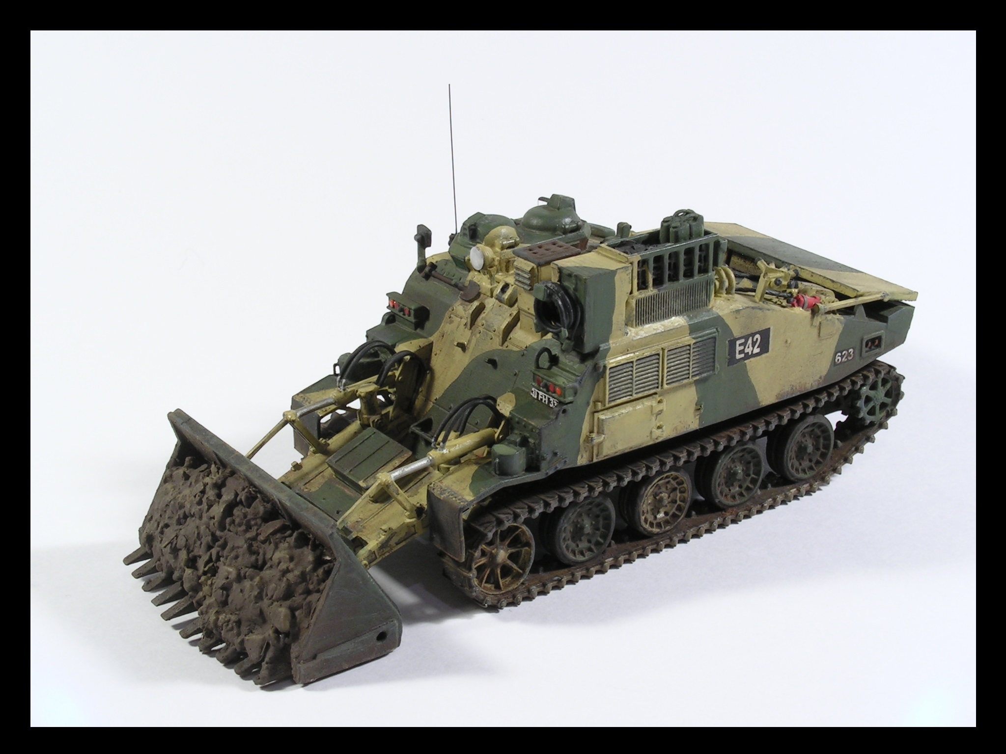
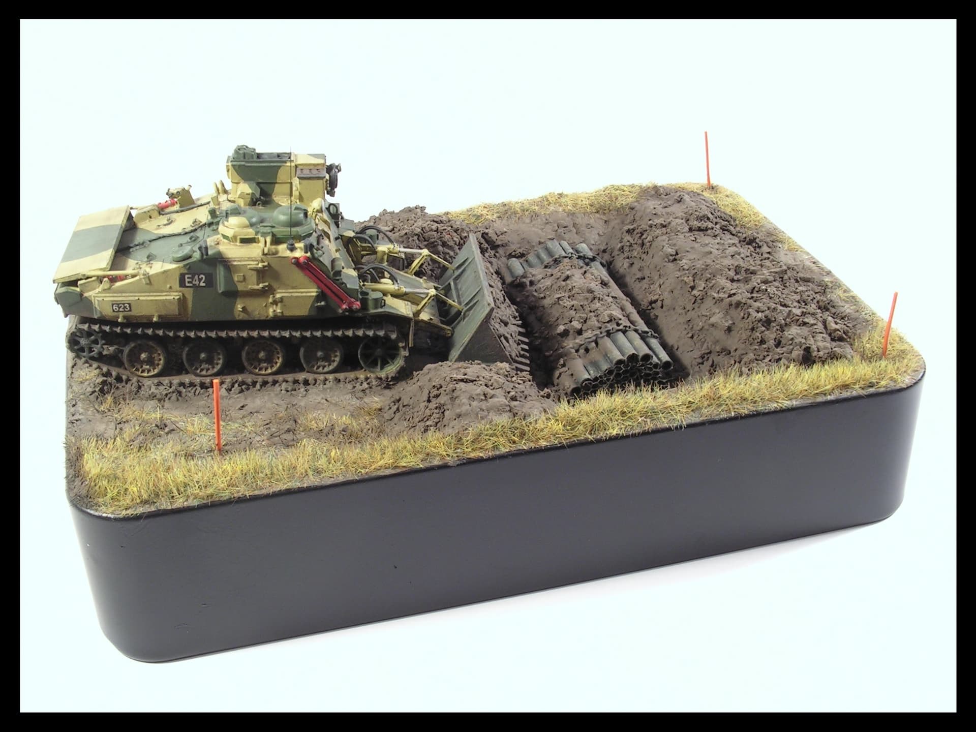
At last I am able to share photos of my latest creation, based on the 3D printed model of the Combat Engineer Tractor from Badger 3D. The model is scaled at 1/72, and is seen here as a vehicle operating at BATUS (British Army Training Unit Suffield).
While the 3D printed item is outstanding in terms of accuracy and detail, I did add a few items (based on reliable reference images).
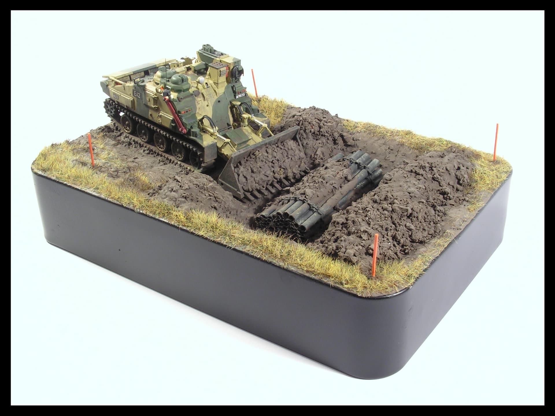
Oh yeah and that base is excellent too!
Can you tell us what paints and weathering products you used on the model as well as the diorama base? Again fantastic job!
I’m not used to 1/72 scale, so I don’t know what levels of fidelity are possible.
I’d have three observations.
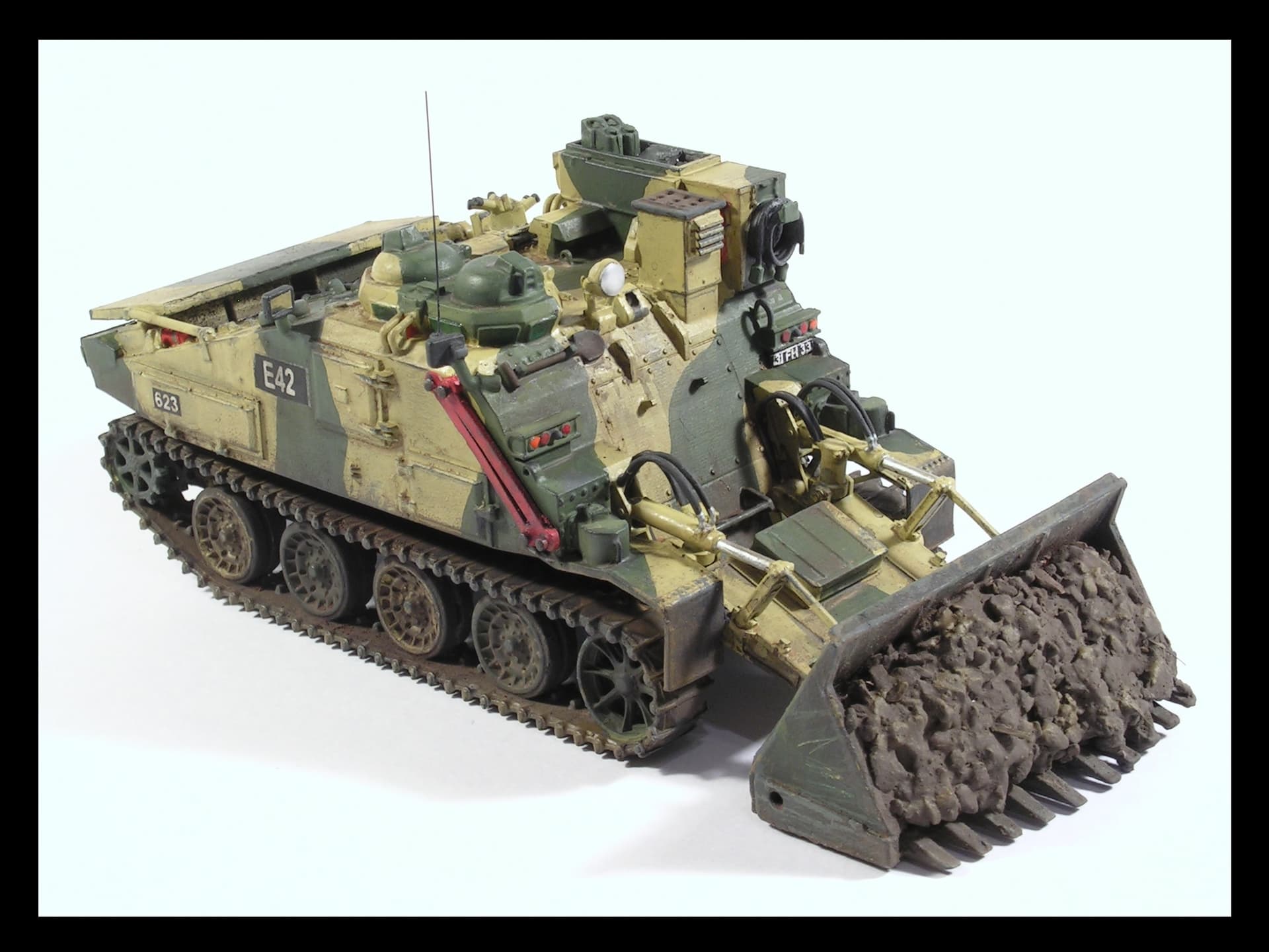
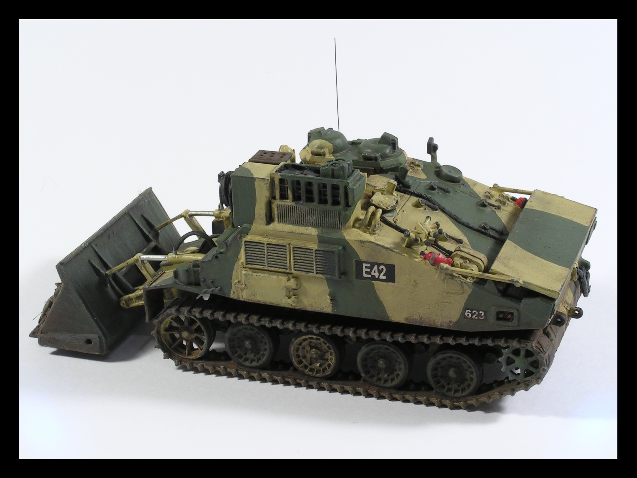
I personally don’t recall that the jerry can frame on the rear was mounted where you have it. It was always mounted on the engine access hatch itself, about 1/4 of the way up from the bottom. There were two brackets/lugs a little higher up to each side so that a retaining strap could secure the jerry cans in the rack. I have seen pictures of the jerry can frame on the main body like you have it, but in those cases, much lower down than you have it.
The winch rope is way, way out of scale on this model. At 1/72, I would expect it to be no more than 0.3mm in diameter.
It was very, very rare (I never saw it) to have an earth bund on the ‘friendly’ side of the obstacle. Ditching is done in order to maximise the effort required to breech it - hence all spoil was placed on the ‘enemy’ side of the ditch in order to increase its size. Ditches were deep, they would swallow a single fascine whole with a good 3’ - 4’ of a gap between the top of the fascine and the edge of the ditch - and hence, the bund would be around 2 - 3 m high.
‘T-Pushing’ was the most common method employed to construct an AT ditch.