Great updates ![]()
Thanks John, ![]()
keep your fingers crossed guys! ![]()
Manfred, it gives a great pleasure to look at your work. The amazing thing, it’s only round plastic rods…cut, arranged, and glued in specific ways and the end result is Wow…that looks cool and I want to see more.
You know there just became an opening for the new bridge designer down in Baltimore. Last designed sucked ![]()
Thanks Mike for your nice compliments, ![]()
work with pros one time … ![]()
Hello everybody,
all well and good, but in the meantime I’ve thought that it would be better if I’d not scratch individually the the black MLI Blankets to cover the three rod systems, but to scratch as a cohesive unit. 
As for the line-like markings, labels, blanket closure tapes, or whatever on the blankets, I wanted to base myself on the following Psyche mission video
for the sake of simplicity and make do with that. 
That’s why I’ve first created the following Screenshots of the corresponding three views of the blanketed rod systems,
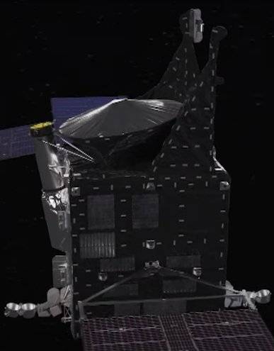

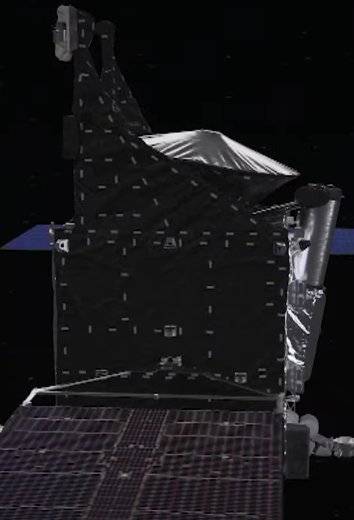
and then combined them in MS Word in a photo montage at the scale of my model solar probe. 
And after a tricky adjustment of the size of the individual graphics, I finally managed to create this coherent unit, ![]()
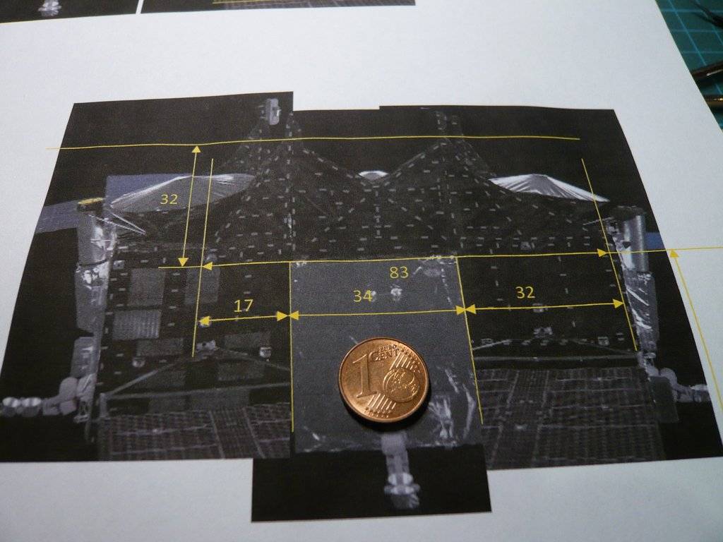
on which the connected rod systems also fits quite well. ![]()

So far so good.
Then there was a well-intentioned critical but helpful note by an expert in NSF Forum regarding the biggest mistake that modelers make with blanketed surfaces is making them too wrinkly,  which made me sit up and take notice,
  especially since his lucid explanation made me understand the technical sense of these blankets.
 ![]()
Accordingly, a thermal blanket consists of thin, flexible polyester layers, which are separated from each other by layers of Mylar scrim. These blankets don’t function properly when the layers touch each other, which is why they are puffy and don’t lay perfectly flat, making them look more like a loosely wrapped package, but definitely not crinkled. ![]()
And that’s exactly what the blankets look like in this well-known image, like a kind of airy wrappings, I would say. 
That’s why I went back to the dark Robidog foil,  which I initially wanted to cut it out using this rods system template, but I quickly rejected it because attaching it to the rod systems would have been too tricky.
 ![]()

That’s why I left plenty of overhang that was intended for blanketing of the inside.
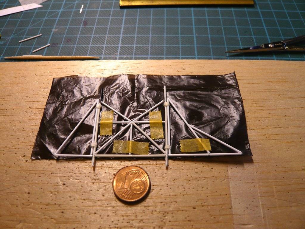

But then there is also still the problem of applying the markings/labels/blanket closure tapes, which would have to be done beforehand, whereby my previous painting with the Permanent marker (Montana Acrylic) still was not convincing me. 
And after some thought, I came up with the following idea. ![]()
Long time ago I completed my collection of masking tapes of different widths with black tape (0,5 mm), which I’ve remembered, cause it’s exactly the needed width. ![]()
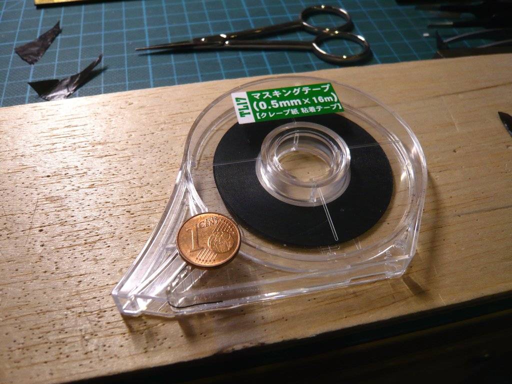

And then I experimented a bit with it and made short lines with the marker,
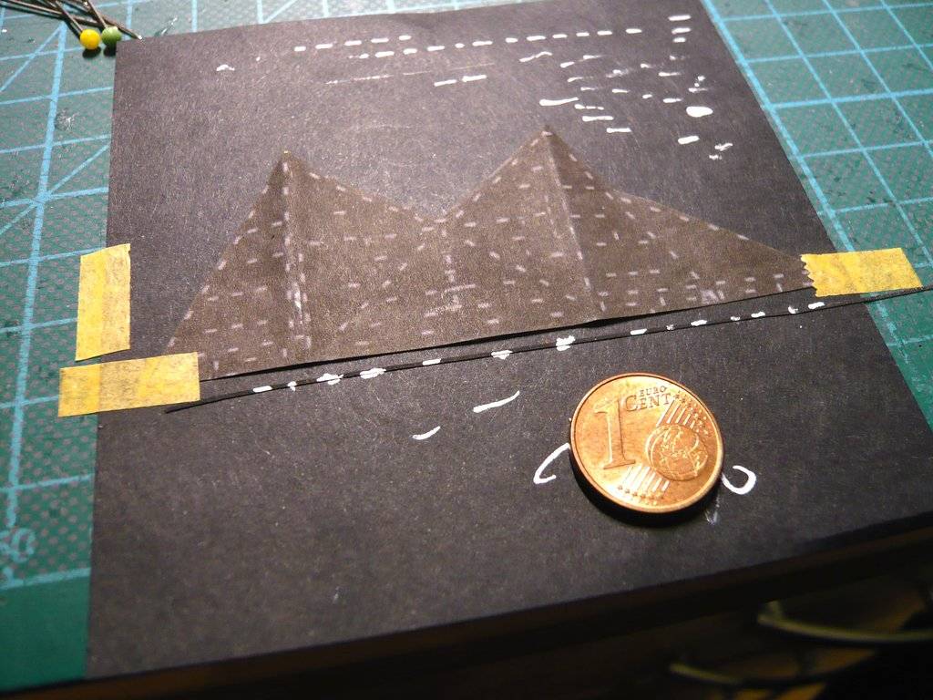
and glued strips marked in this way onto the dark foil, which looks quite acceptable. Above that is my first too flat panel glued to cardboard for comparison, where marking by hand was more or less a matter of luck and also quite time-consuming. ![]()
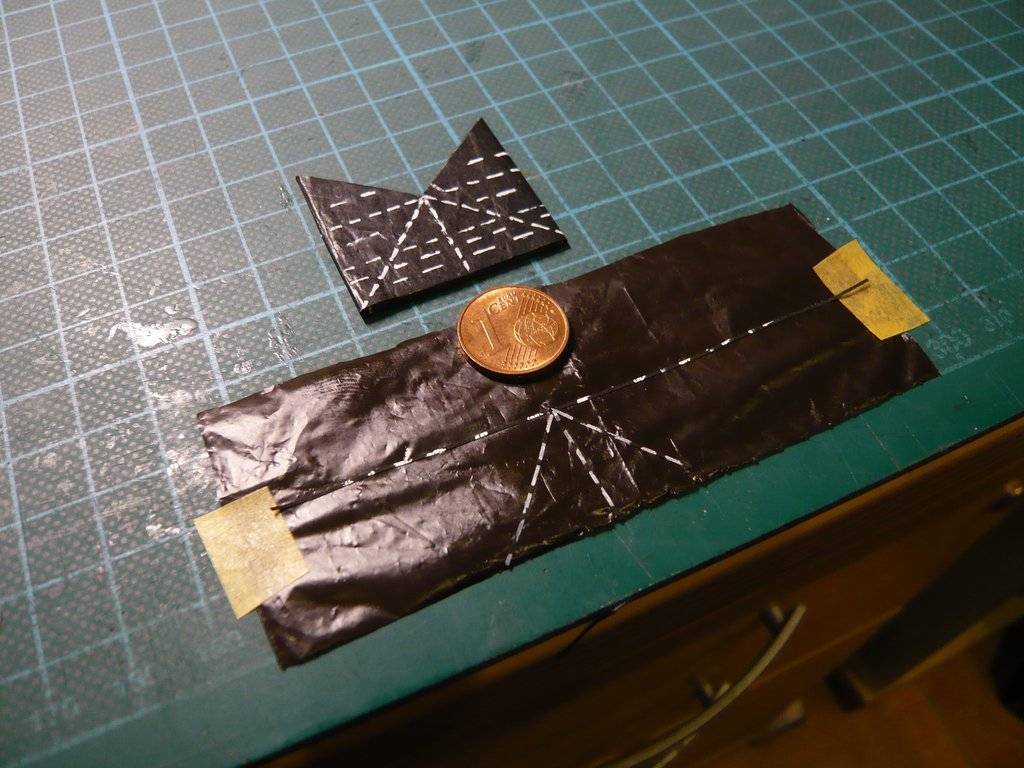
The new technique can definitely still be improved by preparing strips with dash spacing according to the template, which can then be glued before applying the blankets.
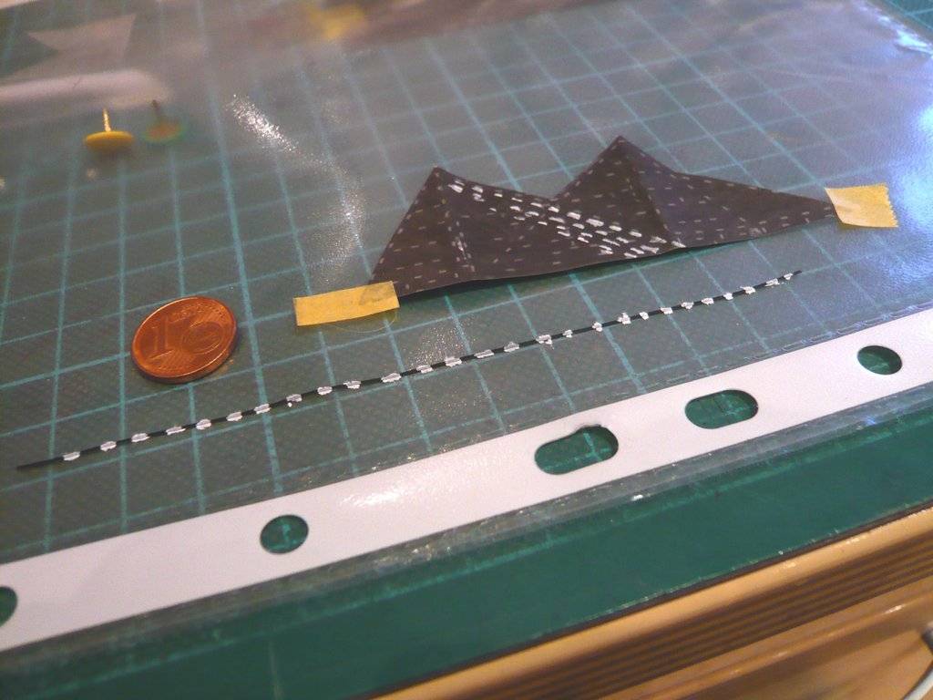
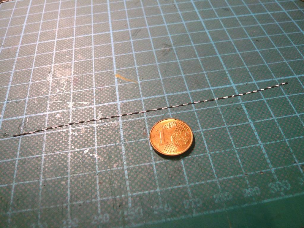
I believe that I have found with it a more suitable solution for marking of the blankets and blanketing of the rod systems. 
But before I continue with the rod systems, I will probably blanket the remaining sides of the solar probe first. ![]()

Very nice … Its so easy to forget about this being based on a cardboard kit … great work as always
Thanks John, ![]()
and I try to improve it a bit. ![]()
![]()
Knowing you now I would not expect anything less ![]()
![]()
![]()
I’ve obviously spoiled you already quite a bit. ![]()

Hello everybody,
after my German travel report Florida and Visit to the KSC 2023 is finished, the construction of the Psyche Space probe can and should continue. 
To get back in, I’ve started to stick parts of my prepared tape strip with the markings of the insulation blankets around the lower part of the X-Band High Gain Antenna, which actually turned out pretty well. 

As one can see in this picture, the stripes appear to be placed completely haphazardly, sometimes horizontally, sometimes vertically,  so the exact directions and distances are not so important anyway, which is why I wouldn’t have to mark the stripes so regularly.
So much for a casual Warm up, so I can definitely continue with this stripe solution for the blankets. ![]()

Hello friends,
next we go with the insulating blankets made of crumpled aluminum foil for the front and back of the space probe, ![]()

with the recesses for the two engines (Hall-effect thrusters), which I want to at least indicate in a simplified form. ![]()


Then came the cutting of the parts for the bottom side from crumpled AE paper, as well as from aluminum foil for the inner coupling adapter,


which I then glued under the black blanket.

Then I created a true to scale template from the 2nd video image for applying the blankets markings.

with which I made corresponding tape strips (0,5 mm), which I then glued to the underside blanket, which was a bit laborious, stressful and time-consuming. ![]()
Since the adapter is set a little deeper into the bottom, I tried to indicate this with a silver wire ring (Ø 0,4 mm),


which I carefully glued piece by piece with UHU CA after trying it on. ![]()

On the bottom and on the back there are further X-Band Low Gain Antennas as additional details,

which I have scaled in this image.

And on the back there are these two Multispectral Imagers that I would like to point out already. ![]()

So all in all there is still some tricky detail work waiting for me on this small space probe, ![]() but everything in its own time, strength lies in calmness.
but everything in its own time, strength lies in calmness. ![]()
![]()
Great update and you have done yet more amazingly intricate detailing … top work
Thanks John for looking in on me again. ![]()
Yep, the closer you look, the more details become apparent. 
As you have seen, building the simple 1:72 scale NASA paper model kit has been a lot of fun for me so far and for God’s sake it doesn’t want to compete with the real thing. ![]()
And the Video animations only help me to call the details by their proper names, nothing more. 
To scratch-build them somewhat to scale, I scale them using original NASA photos or using screenshots e.g. of the faithful model in the Official NASA Broadcast Video. 
Therefore stay tuned, the building of the Multispectral Imagers and of some other details will follow soon. ![]()

Hello everybody,
the blanketing of the probe with the insulating blankets continues, where today it was the turn of the back, on which there are not as many details as was already seen in the last post. ![]()

In addition to the X-Band Low Gain Antenna and the two Multispectral Imagers, which should be comparatively easier to scratch-build, the two complex Hall-effect Thrusters (SPT-140) are far more difficult details, as can easily be seen in this true-scaled NASA model. ![]()
In contrast, this is a highly simplified model representation that could serve as inspiration for the later Scratch-build construction. ![]()
But first, the insulating blanket for the back, which I have already prepared from crumpled aluminum foil, into whose small recess on the underside the finished Thruster will later be glued. To mark the other parts, I again created several 1:1 templates of the back in MS Word in the tried and tested way. ![]()

To ensure that nothing can slip when marking the attachment points of the parts, the aluminum foil was first fixed,

then the template was placed exactly on top of it and also fixed in place. Then I used pins to mark the points on which the X-Band Low Gain Antenna and the two Multispectral Imagers should sit.

After removing the template, the piercing points are clearly visible in the foil.

And now you are probably wondering why besides the three upper points the three lower ones belong to these too, right? ![]()
Well, this question had been on my mind for some time, ![]() which I’ve discussed with the expert in the NSF forum (nasaspaceflight.com), who had already helped me with the Multilayer Insulation (MLI) Blankets.
which I’ve discussed with the expert in the NSF forum (nasaspaceflight.com), who had already helped me with the Multilayer Insulation (MLI) Blankets. ![]()
There I asked about this mounting linkage to the right of the Thruster, which I noticed but had not been named anywhere before, but which I did not want to simply leave out. ![]()

In this image, it can be seen even better from a different perspective to the left of the Thruster. ![]()

This then resulted in an interesting question-and-answer chat, which at first didn’t make me any wiser, which is why I don’t want to go into it in more detail here. But I could come back to it later, as it has again led via interesting cross-connections to another expert, namely David Oh in NASA’s Jet Propulsion Laboratory at California Institute of Technology, under whose direction the Psyche space probe was developed and finally built. ![]()
With this in mind now back to the three piercing points in the foil. ![]()
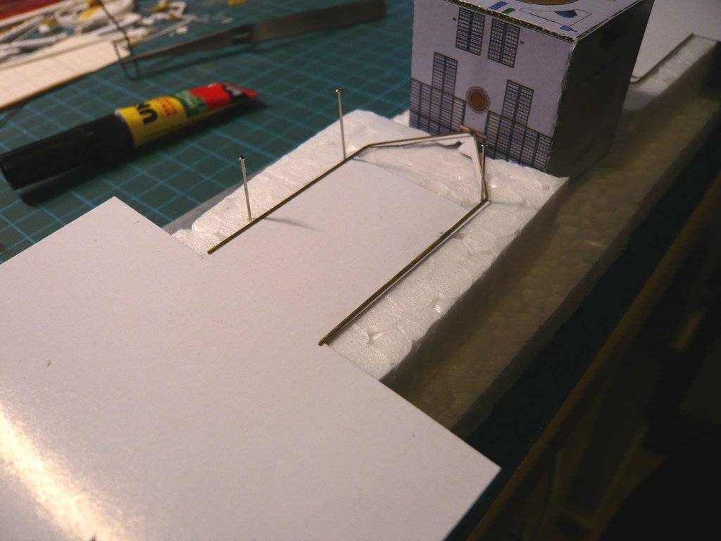
For better visibility, I inserted short round rods into the piercing points.

I’ve still postponed gluing the blanket to the back of the probe for a while, because I had considered not leaving the previously ‘bare’ backs of the solar panels as they were so far, but also refining them with a solar panel structure. ![]()
The paper kit only provided gray panels for this, but which does not correspond to the original and I therefore do not like it. ![]()
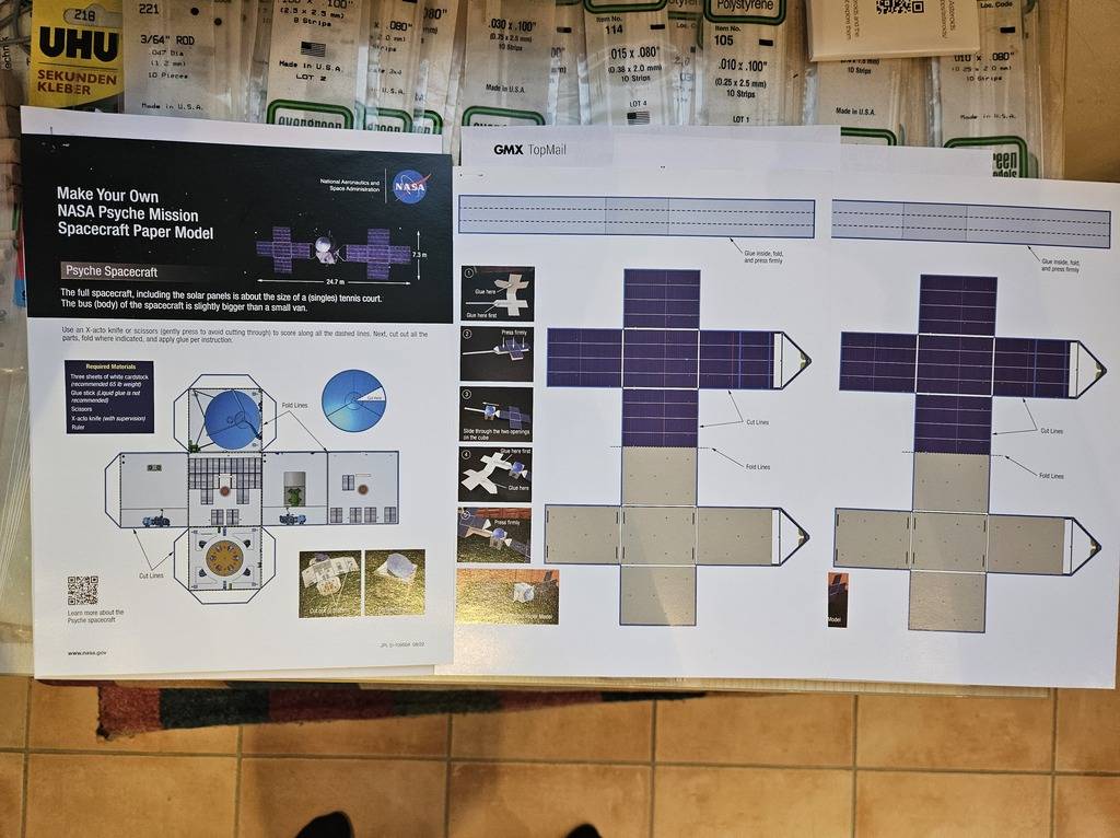
More on the solution to the problem in the next post. ![]()
![]()
Hello everybody,
so let’s get to the backs of the solar panels, which will hardly be visible on the finished model, but would be a blemish so ‘nacked’ as before. ![]()
I hadn’t wanted to cover them up until now so as not to increase the weight of the panels unnecessarily, which could probably lead to the probe letting its “wings” droop. ![]()
To prevent this effect as much as possible, I first copied the top of the Paper Kit Panels onto thin paper (60 g/m2) and have cut it out. ![]()
To glue the undersides, I first had to look for Styrofoam parts with suitable height to avoid causing greater damage, ![]()


which then worked reasonably well. ![]()
To cure, the glued panel was then carefully pressed flat to prevent it from warping. ![]()

And this is what a fully glued panel underside looks like.


And then it was finally done. ![]()

The next step is the blanket for the right side, on which there are a whole lot of details in addition to the marking stripes, the arrangement of which I first have to transfer to a suitable template, which should not be so easy, since I need suitable, as undistorted as possible images, which I laboriously searched for. ![]()
Here as a little foretaste this pretty picture with the details,
or this photo from a final stage, the upper half of the side of which seems well suited as a partial template,
to create a usable photo collage of the side from both images. ![]()
Hello everybody,
next we carry on doing with the insulating blanket for the right side of the solar probe. ![]()
In order to have more freedom of movement when gluing the black blanket paper and to get better access to the side surface of the probe, I first had to think of a suitable jig for holding the probe, so that the solar panels would not be damaged. ![]()

Then I also did a test of gluing crumpled black AE paper and aluminum foil to make sure that the gluing would hold when gluing it to the probe wall and that nothing would go wrong. ![]()
For this I used the VMS FLEXY 5K - XT THIN, a thin superglue for PE parts that I had got some time ago but haven’t tried yet.

And it actually turned out to be excellently suited for these purposes. ![]()

Then I started again in the usual way to scale suitable images from the reference photos of the right side wall in MS Word,


and to combine them step by step. ![]()


This is the template which finally resulted out of it, whose marking strips and modules I can now transfer to the crumpled black paper of the side wall,

whereby this template is also suitable for marking the insulating blanket of the right side rod system on the top of the probe. ![]()
![]()
Some great updates Manfred, and yet more steady, research giving the model even more finer detailing… Lovely work ![]()
Thanks John, ![]()
I’m very happy that you seem to be the only one who keeps looking in on me again and that you appreciate what I’m doing here. ![]()
![]()
Not so fast Manfred, check your Likes! I’m still getting my head around what you were doing a month ago ![]()
![]()
Like Tim said, a lot of people view and admire, but not everyone comments … Keep up the outstanding work ![]()
![]()
