Yeah man, check your likes - I’ve been watching and liking since this was a single sheet of cardboard. The whole construction has been phenomenal.
Hello friends,
and also thanks for Tim and Matthew for liking my work. ![]()
Sorry, but I have to admit that I haven’t seen the likes yet. ![]()
Since I often scratch late into the night or into early morning, ![]() sometimes I can hardly see straight, because my poor eyes start on strike then.
sometimes I can hardly see straight, because my poor eyes start on strike then. ![]()
And even in bed I’m still tinkering with new solutions for scratching these crazy details … ![]()
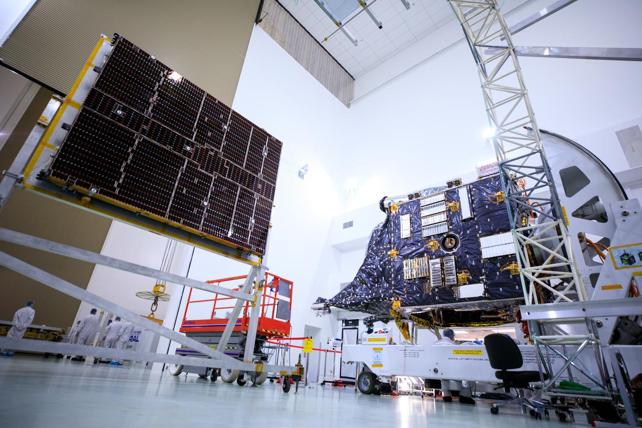
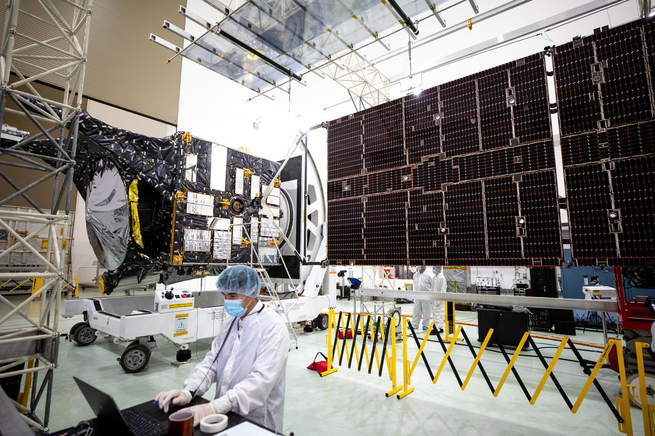
Meanwhile I love this little Psyche Space probe and am trying to make it a bit more like the real thing step by step. ![]()
![]()
Manfred,
For context the now 83 posts has had 1,300 views, 225 likes and 8 different posters.
Only so many different ways to say awesome work, my vocabulary isn’t that deep, more grunts than words ![]() and a
and a ![]() just doesn’t feel correct.
just doesn’t feel correct.
Thanks Ryan for your kind words. ![]()
I haven’t counted the likes yet. ![]()
I know this from the other 5 forums in which I’m posting worldwide. The superlatives are gradually running out and should not have to be repeated all the time too. ![]()
This is my view statistics from a year ago, which should be updated again.

Then KitMaker should also appear in them, alongside our German forum forum.raumfahrer.net (Raumcon), forum.nasaspaceflight.com (NSF), papermodelers.com (PM), arcforums.com (ARC) and britmodeller.com (BM).
Therefore stay tuned my friends and let entertain you. ![]()
![]()

I just had to go do the click, click, clicky click and it’s 10 more clicky clicks added.
Manfred, buddy!!!
Thanks Mike for your sign of life, ![]()
hope that you are well and still a free man. ![]()
Stay tuned and have fun my old fellow. ![]()
![]()
Free at last, free at last. Good God Almighty I am free at last.
Yes, alive, kicking, and screaming…on other drivers that is ![]()
![]() What a good news - what a wonderful world!
What a good news - what a wonderful world! ![]()
Then never drive faster than your guardian angel can fly, brother! ![]()

![]()
Hello everybody,
for comparison, here is the right side of the solar probe as it currently looks in the Paper Kit. ![]()

Although a number of modules are indicated on it, they do not match the original in terms of design, size or arrangement, which is why I have tried to depict these details on the right side in a more realistic way. ![]()
The difficulty, however, is that the photos are usually somehow distorted in perspective in some way, which makes determining the dimensions of details, such as these modules, particularly difficult and time-consuming. ![]()
First, I’ve marked the module positions on the black paper blanket of the right side wall with more than 20 pins.

At the same time, I tried to cut out the larger module group of four (9 mm x 14 mm) from aluminium foil, the division of which I’ve indicated by gluing on my black masking tape (0,5 mm). ![]() I don’t think there’s much more that can be done.
I don’t think there’s much more that can be done.

That means that these modules are not quite so flat and level, which is why I wanted to glue them onto cardboard (0,5 mm) so that they come a little bit higher.

This procedure is only quite stressful, as the marking of the modules on the foil and even more so their handling when cutting out has proven to be quite problematic, ![]() which is why I had to think of a better solution.
which is why I had to think of a better solution. ![]()
Therefore, I first started with the application of the ‘markings’ on the blanket, for which I’ve transferred small dashes onto tape strips by using the white Acrylic marker based on my template,

which I’ve then glued to the blanket, ![]()

which required several corrections. ![]()

In between there are also some ‘horizontal dashes’ that were individually cut and glued. ![]()

In the meantime, I had thought about that it would be easier to draw the individual modules on cardboard and to cut them out, ![]()

then glue them onto the aluminium foil and finally cutting off the overhang, ![]() what also worked great.
what also worked great. ![]()

The tape strips were then glued on.


After they were cut off, the edges were colored with a black marker.

The other cardboard modules were then glued with foil in the same way. ![]()


Then the edges of the remaining modules were blackened too,

and would thus be prepared for gluing onto the right MLI Blanket. ![]()

Then I placed all the modules onto the blanket for testing,

which looks pretty good and definitely meets my starting imaginations. ![]()

Before gluing the complete blanket, I have still to think about where I have to separate it in order to get past the holding rods of the solar panel. ![]()
Maybe I can come up with a clever solution. ![]()
![]()
Such a great amount of effort going into this to bring out all these little intricate details… And the euro piece reminds us just how small this is …![]()
Incredible work on this. It all looks outstanding.
Thanks John and Tom, ![]()
your praise motivates me for keeping on this stony way, ![]() what means every day a new challenge for me.
what means every day a new challenge for me. ![]()
The effort is already borderline and, above all, costs a lot of time, ![]() but my attention to detail still knows no bounds so far, and there is definitely still room for improvement.
but my attention to detail still knows no bounds so far, and there is definitely still room for improvement. ![]()
![]()
Hello friends,
well, there are only two options for this, either horizontally, above the rod system, or vertically, next to the rod system, although I opted for the horizontal separation. ![]()

Then I’ve glued the modules couple directly above the dividing line, whose position I fixed with the two rulers.


The small module was glued to the right.

Then came the tricky task of gluing the upper part to the right side wall, for which the probe had to be firmly fixed all around to the balsa base so that nothing could slip when gluing. ![]()
I always do this by coating a sufficiently large area of a sheet of paper with UHU “fast bottle” glue and briefly placing the part to be glued in it with tweezers,

which means the underside is coated with glue. After that, however, the gluing of the part in place has to go quickly, although slight corrections are still possible, but then it has to fit. ![]()

And as one can see here, fortunately it worked well. ![]()


Then it was actually the turn of the lower half.

But then I came up with the following crazy idea. ![]()
As one can see in this image, some of the modules are not mirror-smooth, but have a stripe-like structure, ![]()
which I’ve tried to indicate for fun with thin lines with a black Pigment liner (0,1 mm). ![]()
And since it actually looks pretty good and is a little bit closer to the original, it was worth the effort for me. ![]()


And that’s why, in a daring move, I’ve very carefully configured the two modules that were already glued together in the same way. ![]()


I just can’t get enough, it’s like a drug. ![]()
![]()
Hello everybody,
and therefore I have optimistically configured the relevant Modules on the lower part of the Blanket in the same way. ![]()


When gluing the four-part-module I had to take into account that it had to have a little overhang,

which I did by eye based on the 1:1 template. ![]()

The coordinates of the other five Modules were then measured and glued oriented to distance markers, as well as briefly aligned. ![]()


Thus, the lower part of the right Blanket was also completed,

and can now be glued to the lower half of the side wall, what I will do tomorrow in daylight. ![]()
![]()
My eyes hurt just watching this!!
Sorry John,
but that wasn’t my intention. ![]()
Cheer up, I hope I’ll be done with this crazy thing soon. ![]()
![]()
I don’t know. I think NASA needs to call you back to work cause you’re sniffing to much glue cause the detail is getting out of hand. ![]()

Hello everybody,
so let’s get to work on the tricky gluing of the [color=blue]blanket bottom part[/color] on the right side wall. ![]()

Thereto I turned the probe over and weighted it down with copper blocks on a suitable Styrofoam base and additionally fixed it.

When gluing the blanket, the UHU Flinke Flasche with the wide spreading surface was used again. ![]()

With a little skill, the lower part was glued to the dividing line below the panel holding system almost perfectly right away. To correct the position, I quickly picked up the probe again, which made the alignment a bit easier.
And the result is definitely impressive, which is why I like it. ![]()


Then I looked at the left side wall of the probe, on whose blanket there are similar Modules, which is why I can proceed in similar way.
First, I will make a template for gluing the marking stripes, which is why I have to take another closer look at the NASA model videos. ![]()
And this is the result of the [color=blue]photo-montage[/color], which is perfectly sufficient for applying the ‘markings’ on the left side. ![]()

Then we’ll see further. ![]()
![]()
Looking very good … Panel looks terrific now it’s on.


