Construction of the Space probe for NASA's Psyche Mission

Hello everybody,

and lo and behold, a direct hit! I knew there was still a bit of work to be done.


Source: NASA

However, the original is a few steps too complicated to use as a template for the replica, so I’ll stick to usable views of the NASA model video, which show less detailed but feasible blanket markings.

I won’t be able to get a proper picture of the locations on my model until I’ve tried out the three-sided rod system with the blanket cover on the probe, along with the X-Band High Gain Antenna, which has to fit between the rods and takes up quite a bit of space.

As you can see from the top view of this picture, the back blanket cover isn’t a smooth wall but has a certain depth,

as one can also see here in the original.


Source: NASA

And here is the scaled depth of the rod system, which I should take into account, assuming there’s enough space on my model.

I had already considered making the blanket cover one piece and attaching it to the rods, but then I rejected that idea, although at the time I hadn’t yet realized how it would extend forward.

But before I bring back the blanket foil from under the template, I marked the corners of the blanket with pins as a precaution to better follow the outline of the back,

Which will be continued next time.

3 Likes

Hello everybody,

now I had to think carefully about what to do next, as the whole thing turned out to be a bit more challenging than I had initially thought. And with the three-sided blanket foil nothing could go wrong because there was just too much work involved.

So, in the next step, I removed all the pins and carefully cut out the blanket, leaving folds all around so I could glue them onto the rod system. This sounds a bit confusing and complicated at first, but it makes sense.

The only difficult part was the exact fixation of the rod system on the back of the blanket, which had to match the marked tape strips on the front, which are unfortunately invisible, which is why I thought a while about a solution for a long time.

But then I had the idea! I just had to attach the blanket with the front somehow to the window pane so that the marked tape strips could be seen through the foil and then fix the rods on it with small tape strips. So much for the theory.

To make my work easier, I used tape strips to stick the blanket foil to a transparent foil,

here is a view of the front.

I then attached the transparent foil with the front of the blanket foil to the window pane with Tesa tape, then aligned the rod system on it and carefully secured them with tape strips.

On the work table, I then removed all the tape strips from the transparent foil,

and thus exposed the blanket foil with the rod system attached to it and started to glue the adhesive folds on the rod system with UHU CA,

first on the underside of the rod system, as one can see here.

And so it went on step by step.

Then I wanted to test how the fixed blanket foil would behave when the side rod systems were bent 90 degrees, for which I inserted the two rod system columns into a Balsa plate.

Since the test was successful,

I then glued all the remaining folds onto the rod system,

which completely secured the blanket foil onto the rod system.

The next step is to make a test fit of the rod system on the space probe, which I’m looking forward to.

4 Likes

Hello everybody,

so then to the test fitting, for which the rod system was quickly attached.

After bending the sides I added side boundaries by using insect pins.

Then I added the X-Band High Gain Antenna, which just barely fits in between.

Now I still needed the blanket foil for the inside of the rods, for which I used the existing template, but it had to be slightly smaller. So I carefully marked the protruding edges, which was a tricky job.

Then I marked the rear edge of the antenna, to which the inner blanket foil must at least reach.

For the final cladding of the inside, I inserted the rod system back on the small Balsa plate and fixed the side walls,

and trimmed the edges of the template for the interior cladding.

Although I don’t have the calculated space behind the rear wall of the rod system,

I wanted to at least indicate a certain width of the blanket cladding, for which I glued in four inner struts.

With this, I can now tackle the blanket cladding on the back of the rod system. Since there are also some of those marking stripes there, as shown in the pictures, I first have to glue the blanket foil with marked tape strips, as before.

5 Likes

Forgot all about this one !! Great to see it back on the go again ….. that looks great built up and the internal frame looks lovely.

2 Likes

Thanks John, and Hi all,

to err is human, said the hedgehog, and stepped down from the barbed wire.

But one after another. First, I started by gluing the marked tape strips onto the blanket foil according to my template, first for the back,

and then for both sides. This continuous blanket could also have served well as the inner lining of the rod system. But that was unfortunately also the fallacy of my thinking, because that would only have been correct if I hadn’t also glued in the [color=blue]inner struts[/color] of the rod system.

But during the first fitting the scales then quickly fell from my eyes, so I’ve immediately removed the tape strips on the sides again.

Since the struts had reduced the available interior space, I also had to reconsider the clearance required for the X-Band High Gain Antenna. This allowed me to cut off the now-unnecessary side panels of the blanket foil and make various cuts along the bottom edge.

Now it can go on with the tricky task of gluing the rear rod system cover.

4 Likes

Hello everybody,

the gluing of the inner blanket cladding was really a bit stressful and involved some tricky snipping, which I’ll want to refrain, so I’ll keep it brief and show you the result right away.

The two upper ends of the rods are also covered with blankets, on which a few details are located, such as this ‘box’, the Gamma-ray spectrometer and below it the Neutron spectrometer,


Source: NASA

which I would also like to at least hint at.

4 Likes

Hello all,

the rod system covered with blanket foil is still missing a few small details, such as the Gamma-ray Spectrometer and the Neutron Spectrometer, as well as the two Magnetometers at the other corner,


Source: Jet Propulsion Laboratory (David Oh)

which also need to be covered with blanket foil.


Source: NASA

So, first I wrapped the upper ends of the rod system with thin [color=blue]Blanket foil[/color], glued and reinforced them.

I had already painstakingly prepared the Gamma-Ray Spectrometer by scratch-building,

which I then glued to the rod system.

I then took the space probe out of the cupboard and attached the entire rod assembly for a test fit, which gives a decent overall impression,

further rounded off by the X-Band High Gain Antenna.

That’s all for today.

4 Likes

Hello all,

next, I tackled the Neutron Spectrometer, actually just a small component, but not so easy because of the covering with the blanket foil, which should also look a bit crumpled.


Source: NASA

Fortunately, I don’t have to scratch-build the actual spectrometer, but only the encased part, for which I wrapped and glued an Evergreen Styrene profile (1,5 mm x 2 mm x 7 mm) with foil,

what resulted in this cute little package,

which was then glued onto the back of the rod system.

The two Magnetomers look huge here,


Source: NASA

but were only indicated by two small stubs of insulating tubing.

Next time it continues on the back of the space probe,


Source: NASA

where, among other things, these two Multispectral Imagers are located and to the left of them an X-Band Low-Gain Antenna.

5 Likes

Hello everybody,

I first determined the dimensions for these two Multispectral Imagers on the back of the space probe.


Source: NASA

As can be seen from this image, these are tiny hollow cylinders (1,3 mm x Ø 1 mm),


Source: NASA

which is why I immediately thought of my small [color=blue]glass beads[/color], which also happen to have the right dimensions.

Then there also the three X-Band Low Gain Antennas are still missing, like these two here on the back and on the bottom, as well as a third one on the front of the space probe.


Source: NASA

These small spherical caps, which have been part of my collection of small parts for quite some time, are suitable for these antennas.

After separation, the hemispheres were flattened and the ridges were filed,

which now have the correct diameter (Ø 4 mm). I’m using the same glass beads for the feet, which would complete the antennas and allow them to be glued together.

The feet are glued on with UHU-CA,

and can now be glued onto the space probe.

4 Likes

The detailing just never stops amazing me.

1 Like

Thanks John, step by step.

Hello Psyche friends,

in the meantime, I have thoroughly reconsidered my further procedure for attaching the electronic assemblies to the space craft body and have specified their sequence.

For a better understanding of the following side names, this image with the underlying NASA coordinate system is intended to help with further orientation.


Source: Jet Propulsion Laboratory (David Oh)

In the next step, it is advisable to first glue the covered rod system and the X-Band High Gain Antenna to the top (+Z Deck).

To do this, it is necessary to lock the space probe in a suitable, stable manner and to support its solar panels with appropriate conditions.

To do this, I clamped the probe body between these two steel angles and supported the solar panels with styrofoam plates so that nothing could slip during the installation of the electronics.

Here the X-Band High Gain Antenna is now glued in place on the top (+Z Deck).

Contrary to my previously planned mounting sequence, it is more advantageous not to continue on the rear (-X-Panel) and attach the X-Band Low Gain Antenna and the Multispectral Imagers located there, but to continue on the front (+X-Panel), where, among other things, the Deep Space Optical Communications (DSOC) optical telecommunications system is located, which is a Laser space communication system that has improved communication performance by a factor of 10 to 100 compared to radio technology, without increasing mass, volume or power consumption. Source: NASA News (Jennifer Harbaugh)

Here is another original photo where you can see the impressive, complex system.


Source: NASA

And this is my humble Scratch DSOC,

which I have now glued onto the front (+X-Panel),

which should now get side support struts like the original.

3 Likes

Looking very very nice …. super work.

Hello friends,

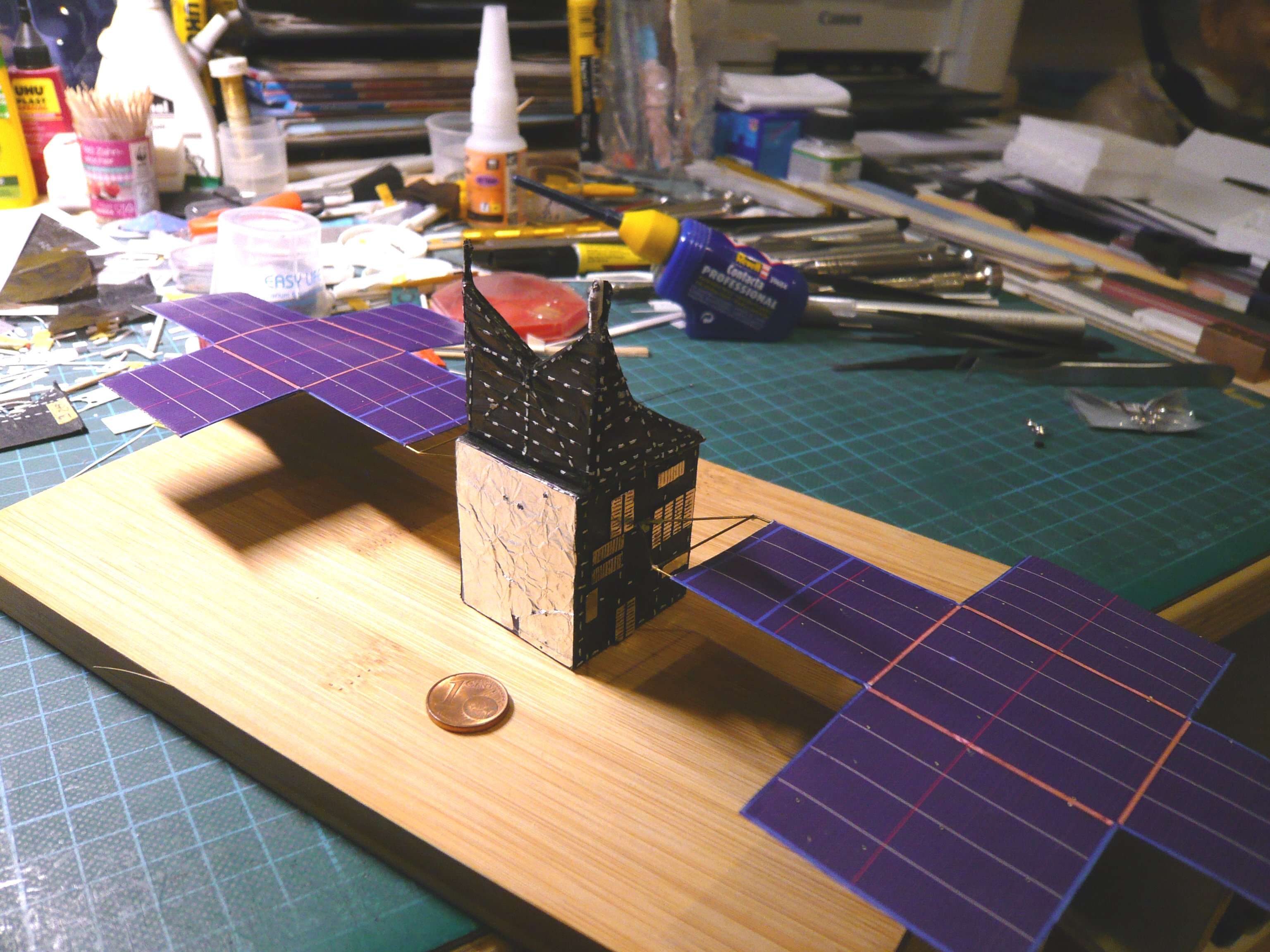
for the DSOC struts I tried two variants.

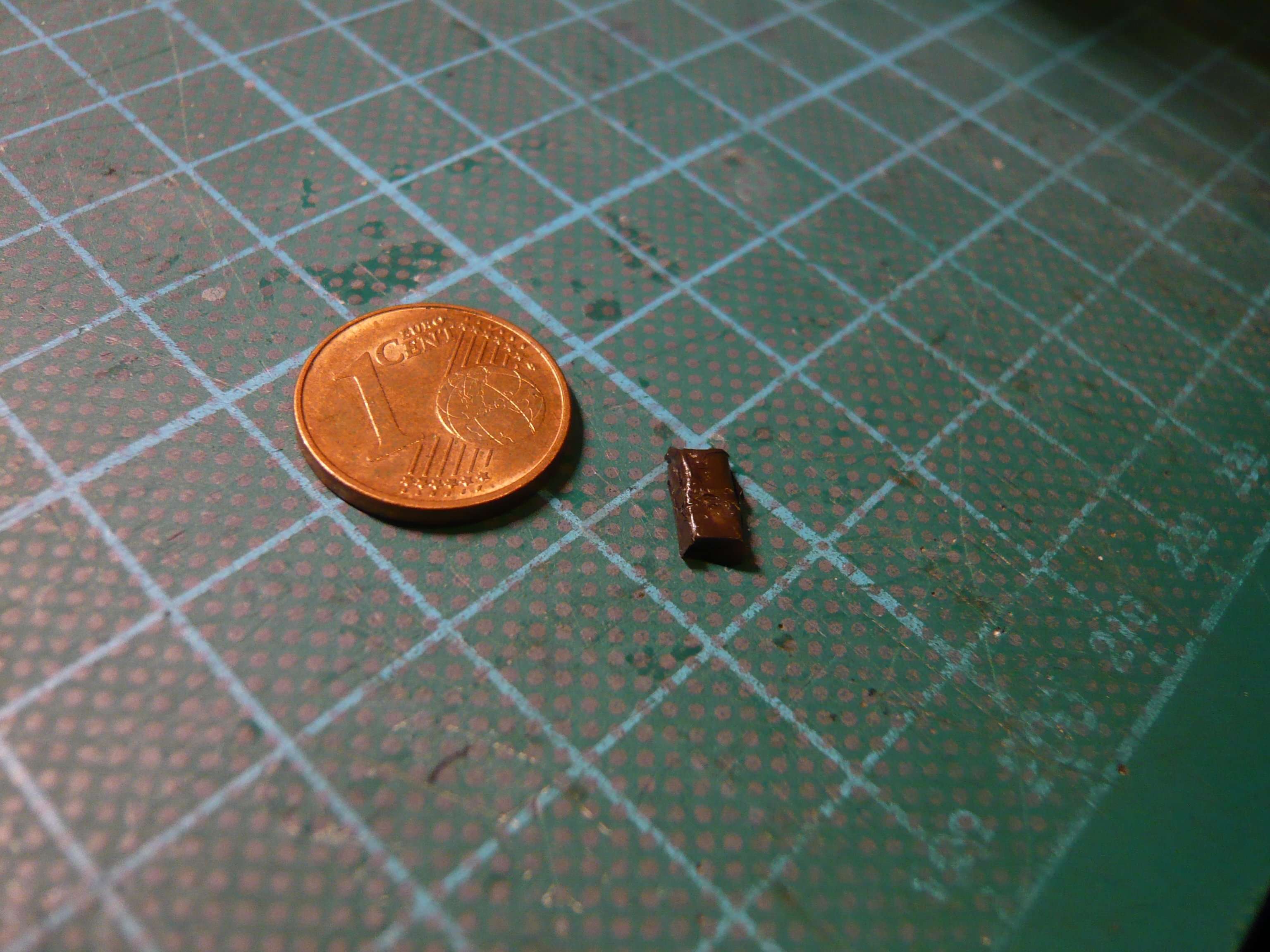
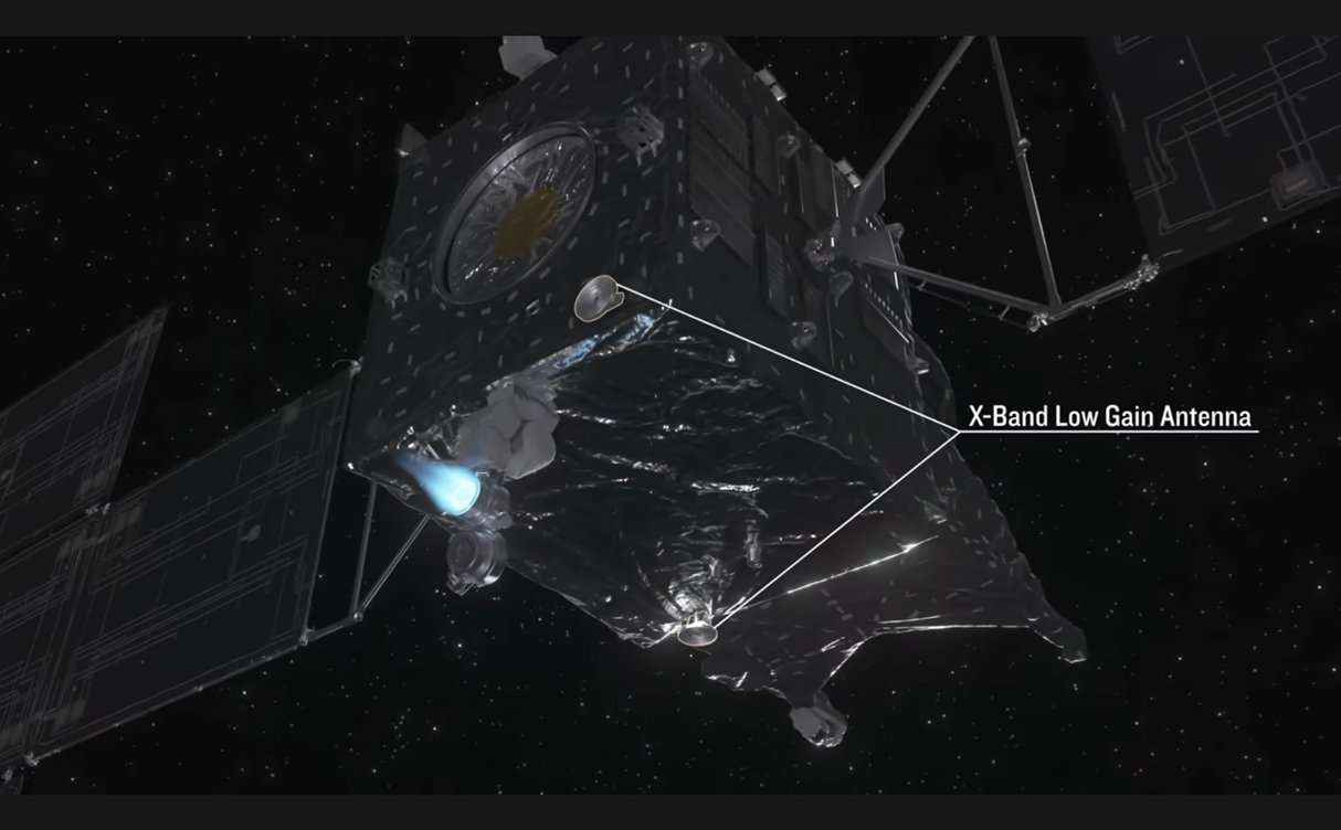
First, I colored an Evergreen strip (0,5 mm x 0,75 mm) black using only a marker (below), but it looked too smooth to me,

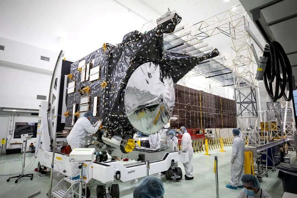
as one can see in the original image that the struts are also wrapped with blankets.


Source: NASAr

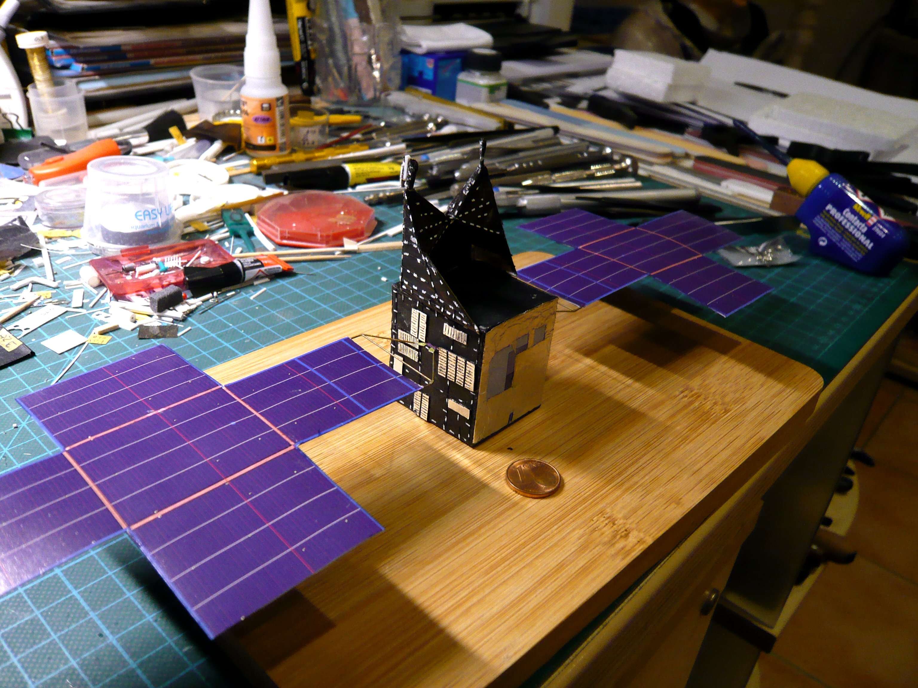
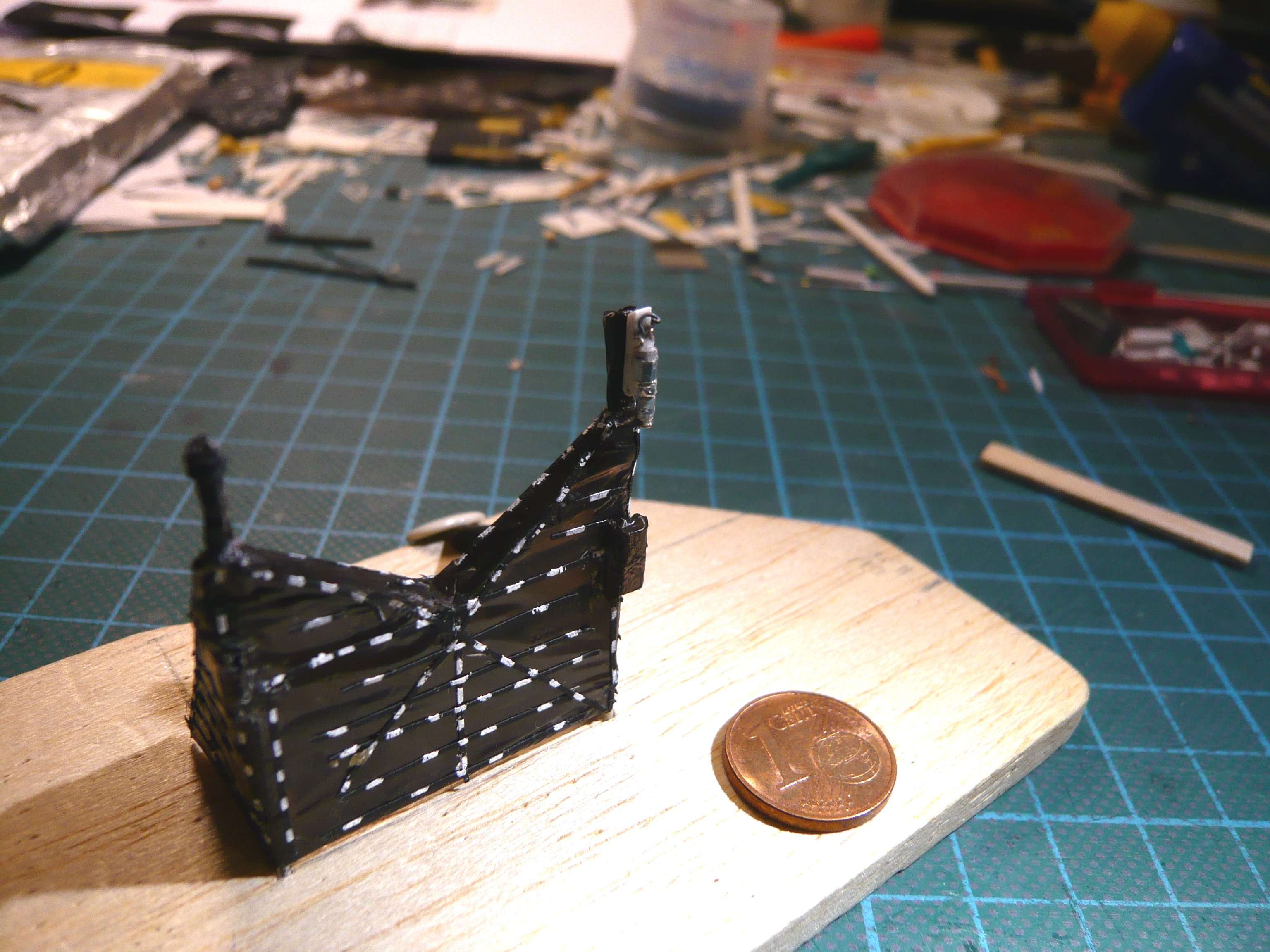
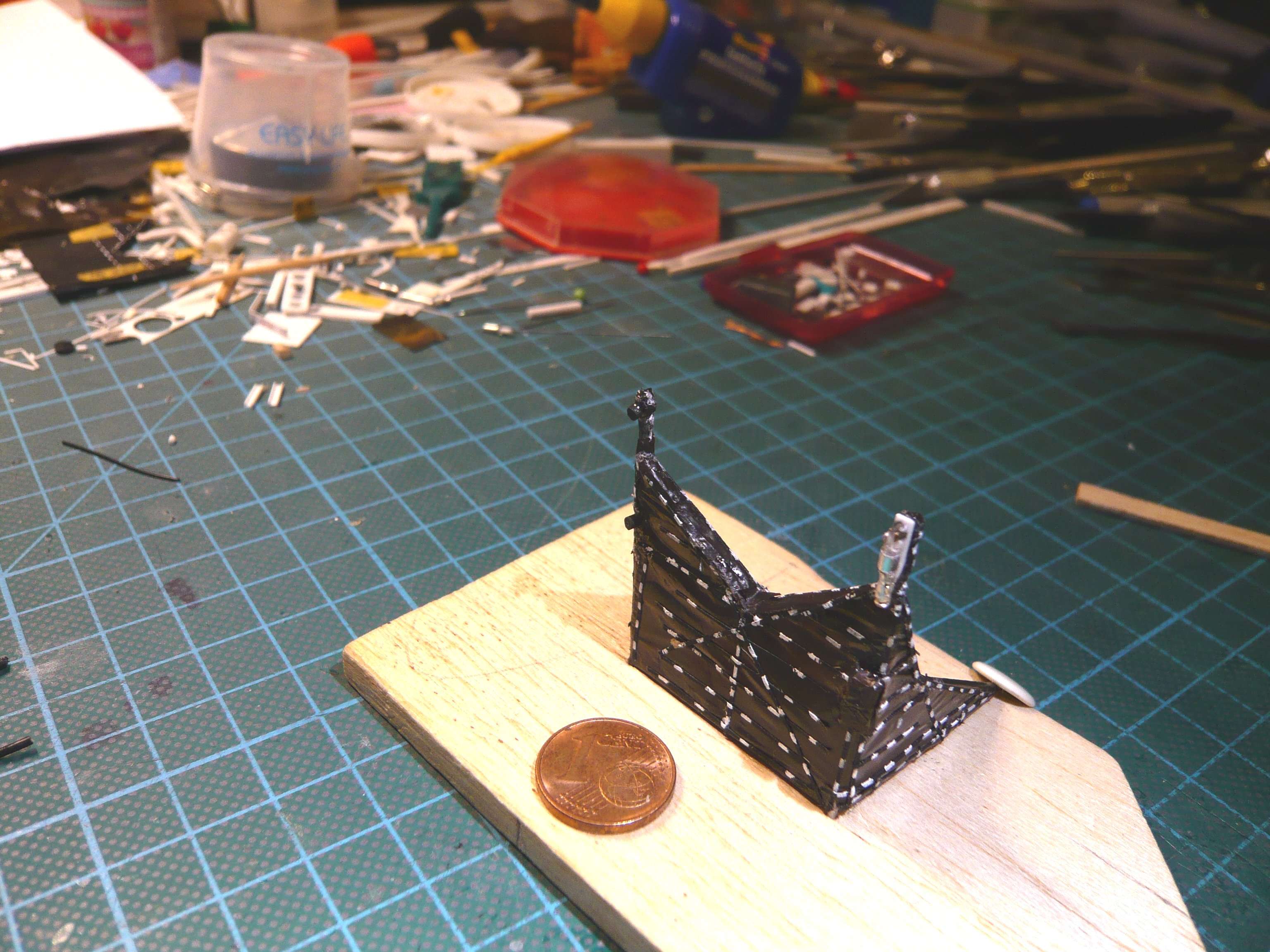
Therefore, I wrapped the Evergreen Strip with black masking tape (0,5 mm), which is much closer to the original and I like it better than the smooth black strip.

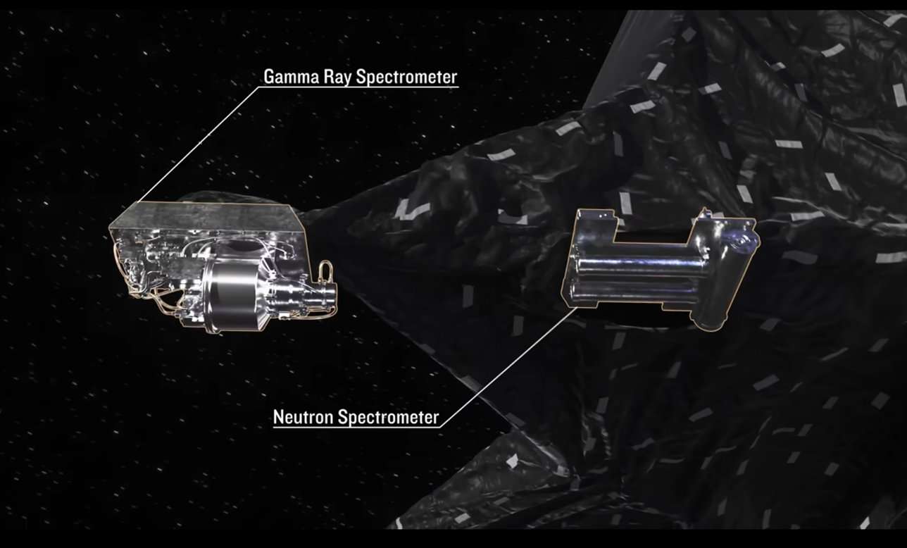
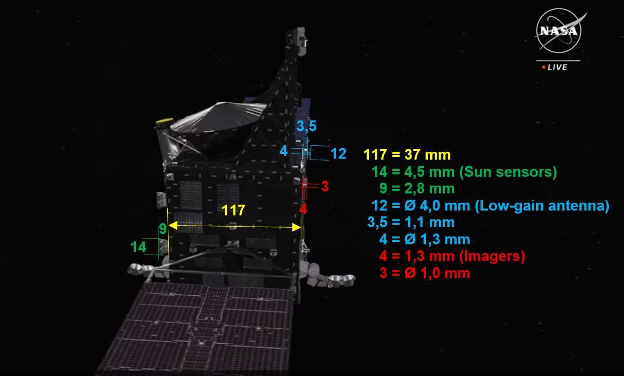
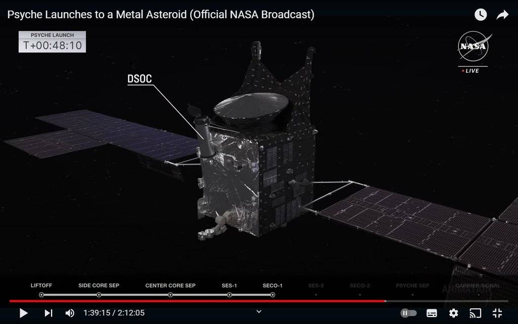
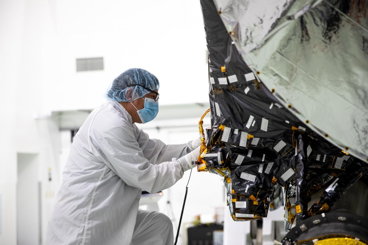
Then I turned my attention to the two Star Trackers, which are parts of the Attitude Determination and Control System (ADCS) of the space probe on its approximately 2 billion-mile journey to the Psyche asteroid. These are two ASTRO APS sensors from Jena-Optronik GmbH, which emerged in 1991/1992 from the former VEB Carl Zeiss Jena combine, a fact worth mentioning.

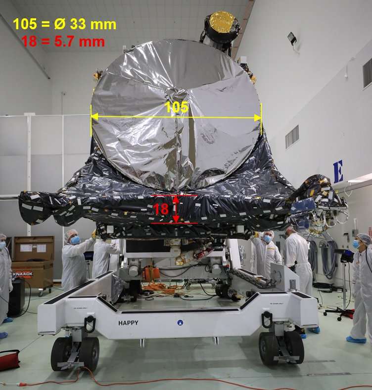
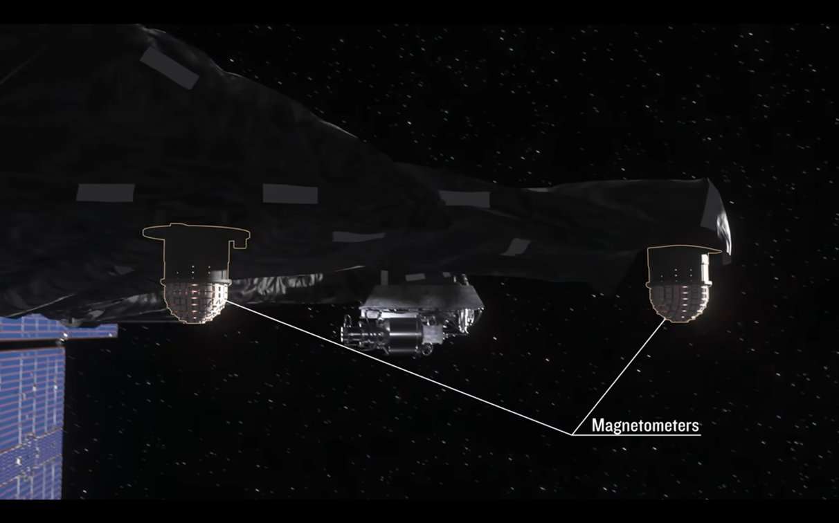
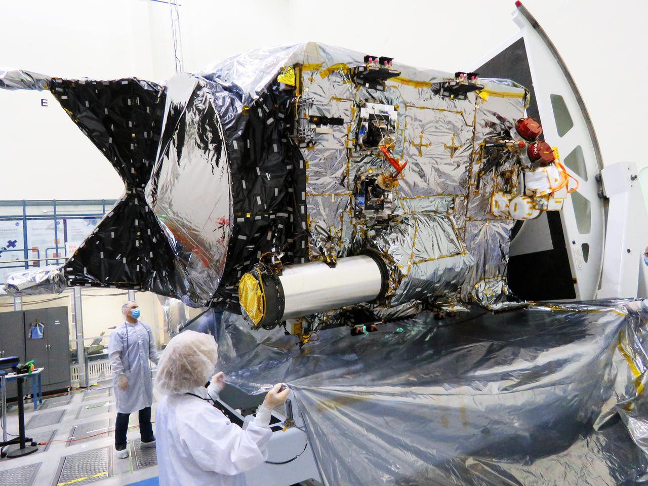
Their dimensions I laboriously determined from this image.


Source: NASA

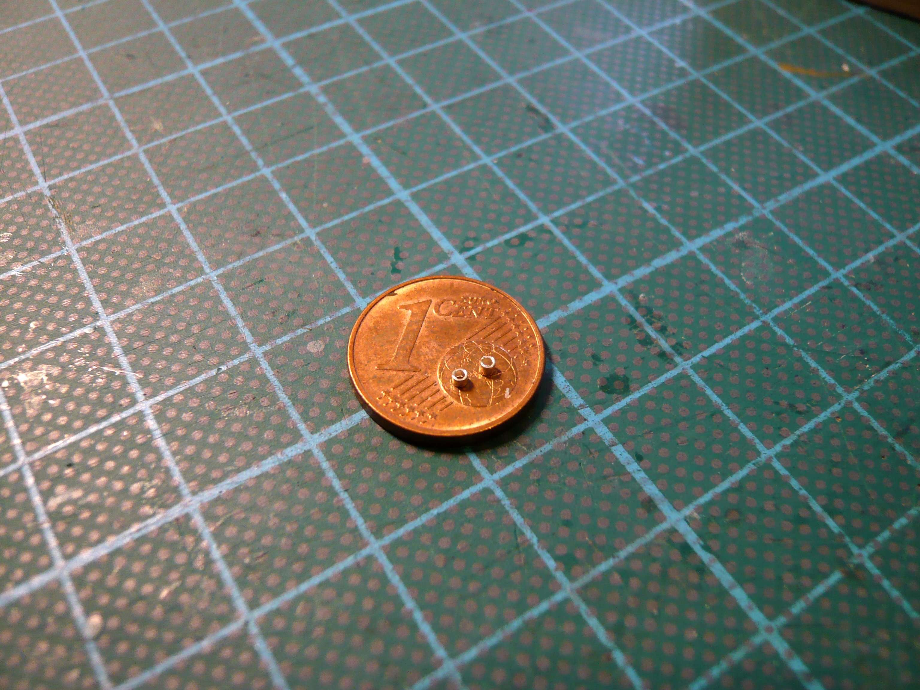
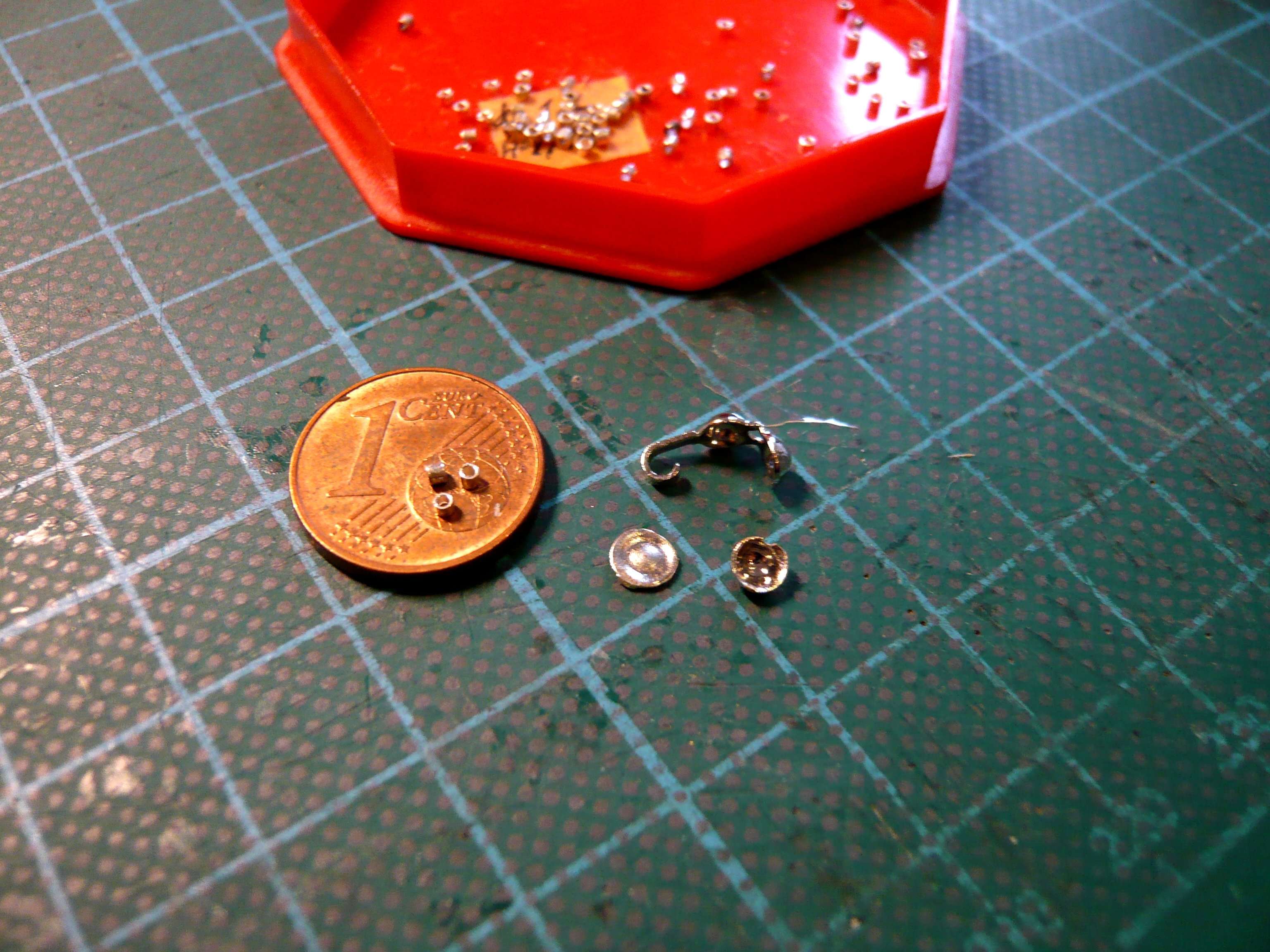
For this I used two plates (5,5 mm x 5,5 mm) made of thin aluminum sheet (0,1 mm) with a central recess, standing slightly raised, and two tiny cones, which I have to file from an Evergreen rod (Ø 2 mm x 2 mm).

Since I cannot mount these delicate little parts directly onto the probe body, it is easier and safer if I contruct each one separately on a base plate made of black paper and then glue them completely onto the front (+X-Panel) to the right of the DSOC.

I first carefully pre-drilled the middle recess with a 4 mm diameter drill bit, and then enlarged it with a mini square diamond file, which was a stressful task.

Initially, I wanted to glue smaller spacers (0,5 mm) under the aluminum plates, but then I went about it differently, as one can see in the image that the white cones are sitting on a black base.

And then I wanted to get even closer to the original and carefully cut out the tiny corners from the aluminum plates with nail scissors, which I had tried out beforehand on a dummy, as well as filing the round rod conically for the tracker cones.

Then I glued short Evergreen strips (0,5 mm x 0,75 mm x 4 mm) around the recess as spacers using UHU CA,

and the aluminum plate prepared in this way was then glued to the base plate, which then resulted in the desired distance from the floor.

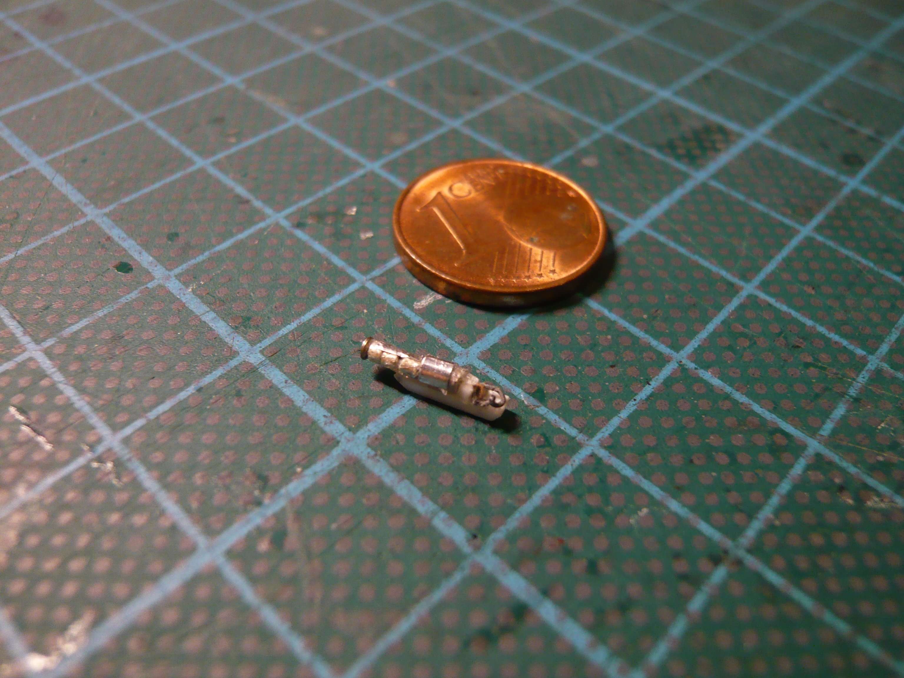
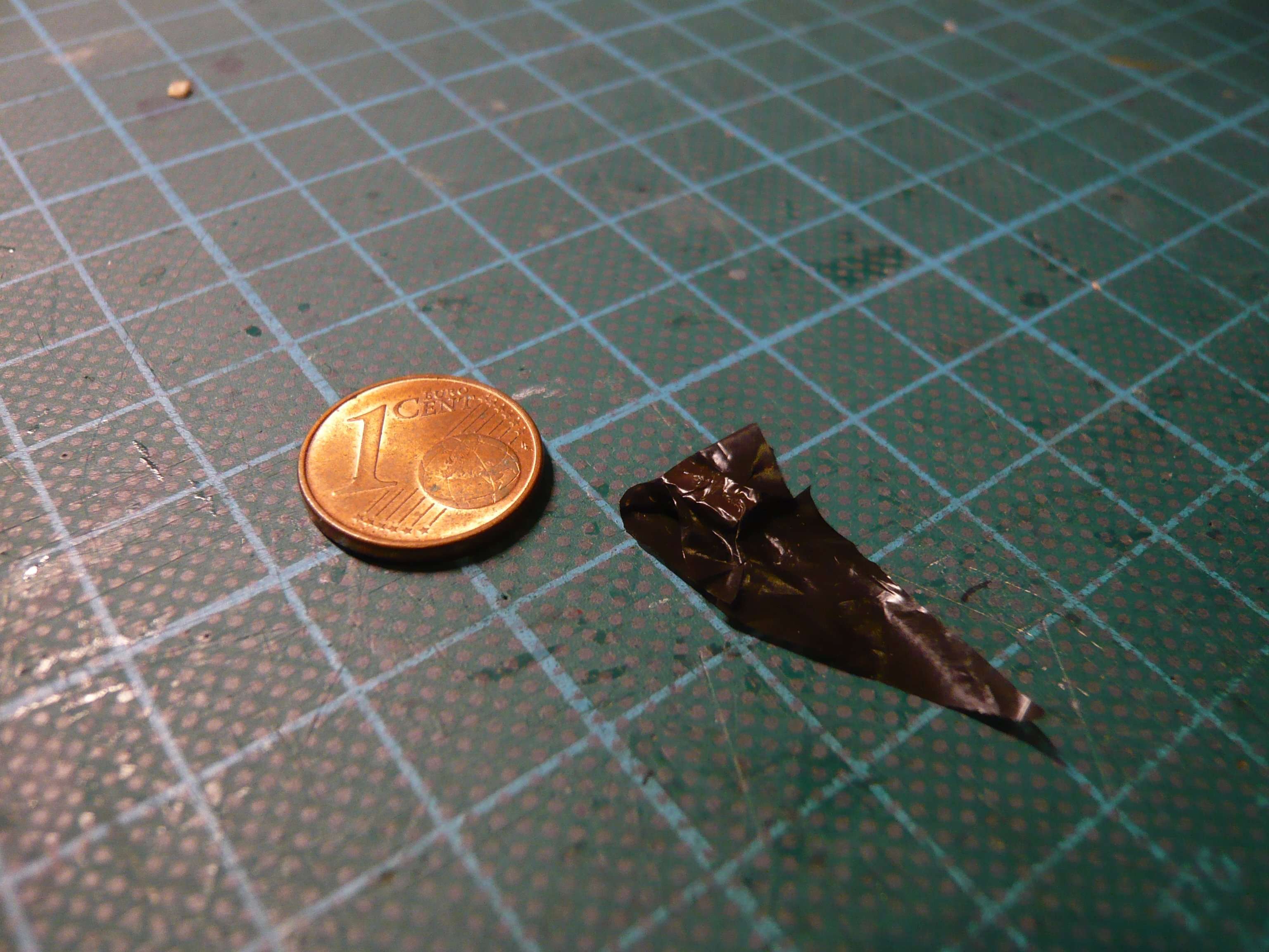
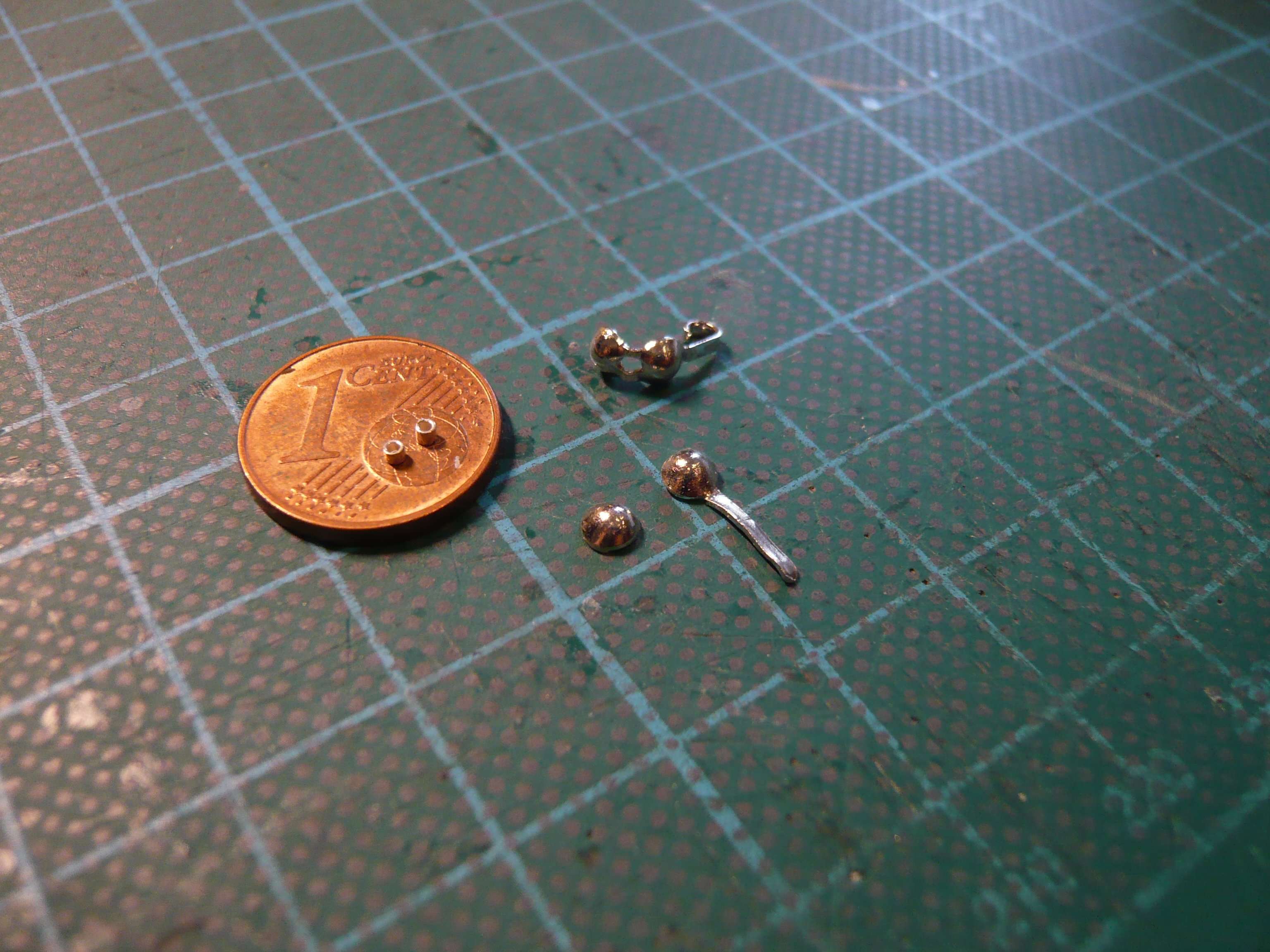
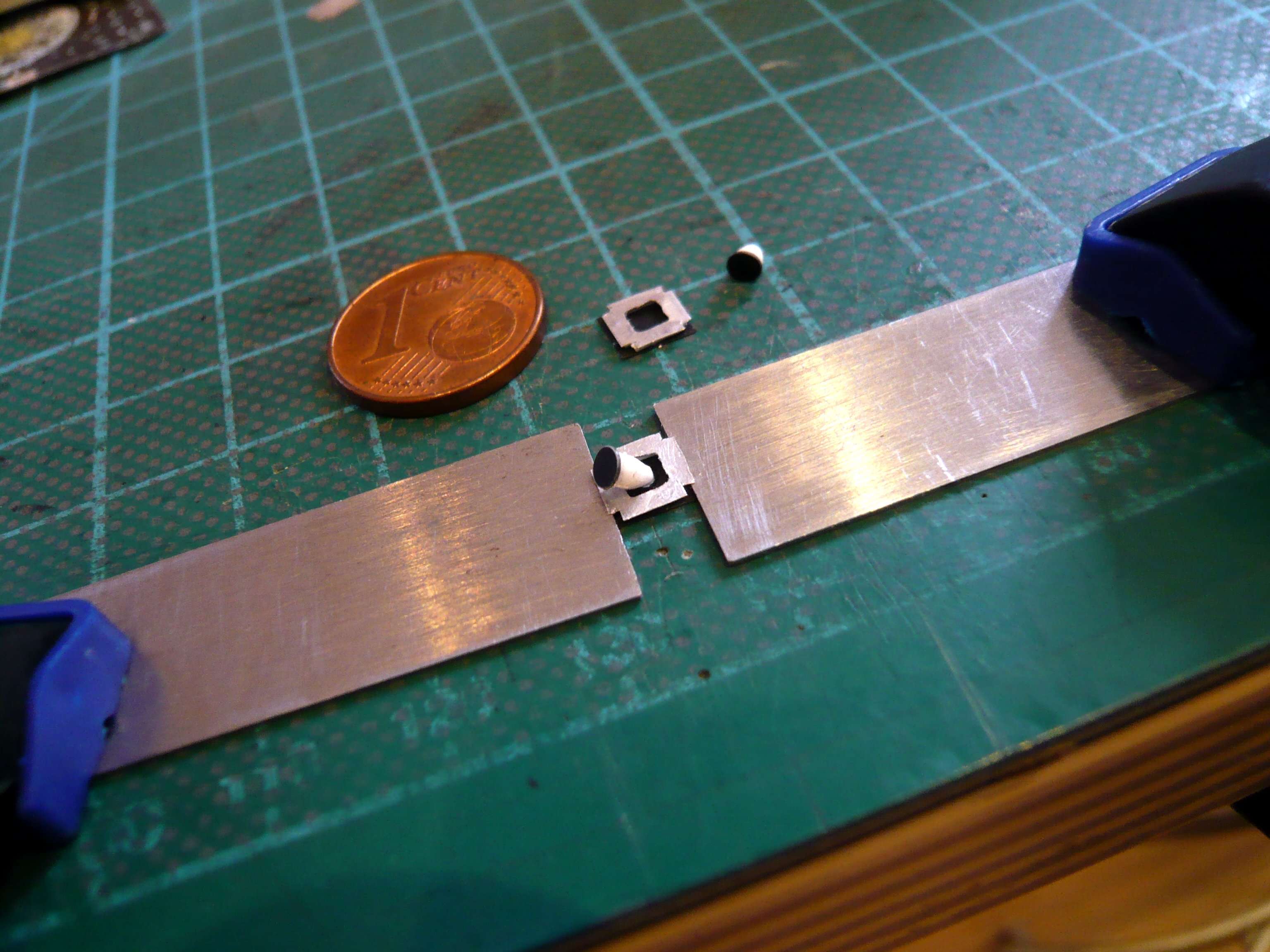
Then I tried to cut off the 2,5 mm long cone, which wasn’t that easy.

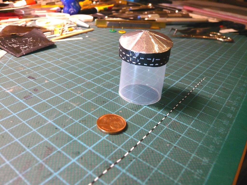
I then wanted to glue a small black disc (Ø 2,5 mm) to the front of the cones. The problem is that these fiddly bits are so small and unwieldy that I had to invent this holder made of masking tape.

Then I carefully placed this cone on the plate and was amazed at how well it corresponded to my imagination.

The second aluminum plate was then scratched in the same way.

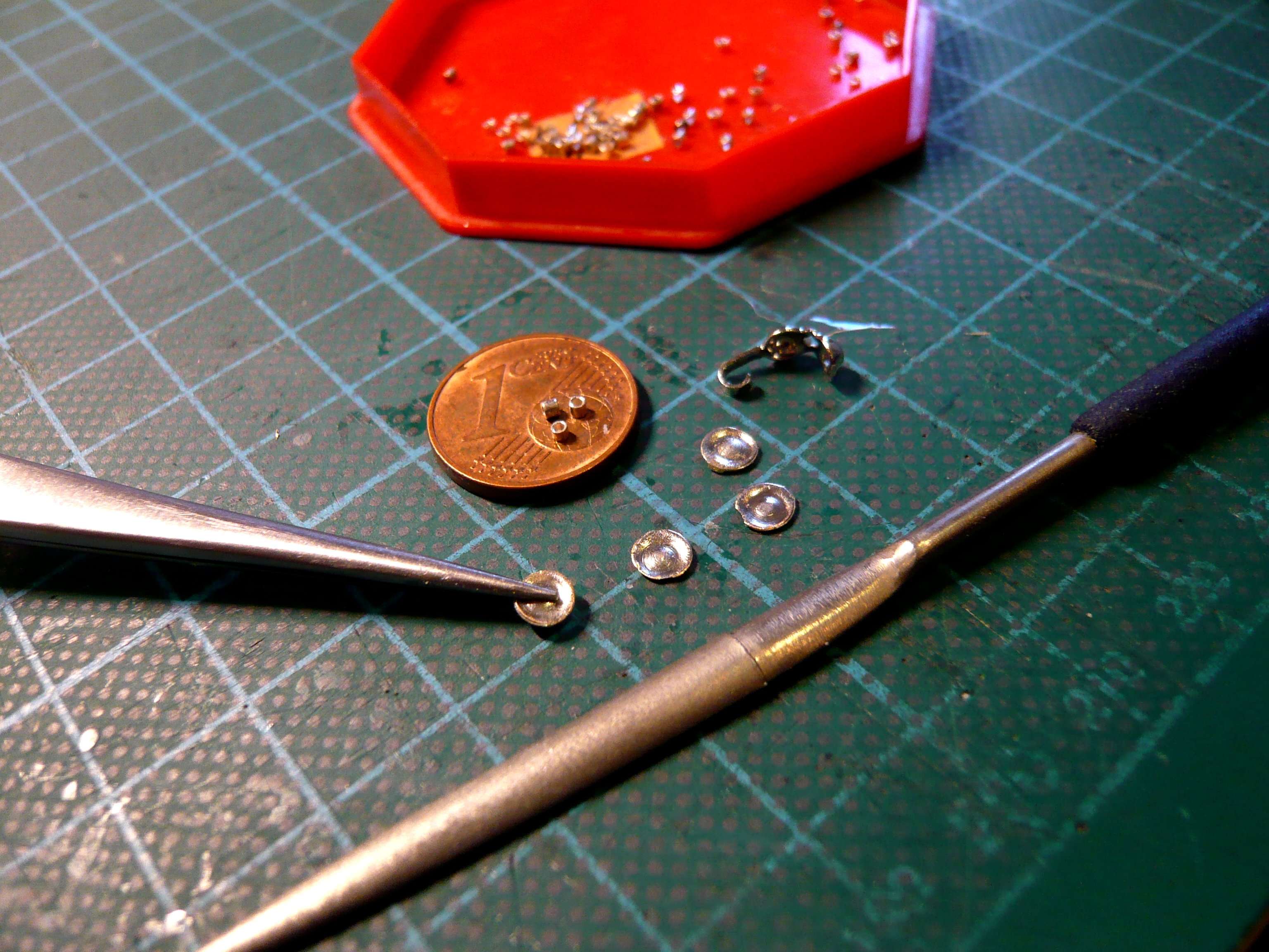
And now I just had to cleverly glue the two cones into the openings of the plates,

wherefore I fixed it between two steel rulers so that nothing could slip anymore.

Then I carefully dabbed UHU CA into the opening with an acupuncture needle, placed the cone at an angle, and adjusted it slightly. Afterwards, I dabbed the cone tip inside the opening with more drops of CA to further strengthen the bond.

I then left both Star Trackers alone to set before I carefully placed them both on the probe to enjoy the great results.

I will wait with the gluing until I have glued the still missing small details on the front and all around, including these Sun Sensors, which I will now tackle.

These are all just small details, but they are very time-consuming and require a lot of patience, from determining their dimensions to final scratch building.

4 Likes

The small details make it :+1:

That’s right, John, even small things can cause trouble.

1 Like

Hello everybody,

let’s stay again with the [color=blue]propulsion systems[/color] of the space probe.

While the [color=blue]solar-electric propulsion system[/color] of the four Hall-effect thrusters (SPT-140) use propellant very efficiently to produce thrust, an additional small propulsive attitude control system was determined to be needed to accomplish short duration, power-critical, and time-critical maneuvers.

For this purpose, the space probe was equipped with a Cold Gas Propulsion System (CGT) consisting of 12 Cold Gas Thrusters (CGTs) installed on the top (+Z Panel) and bottom (-Z Panel) of the probe, as indicated in this image, which initially caused me some confusion, because their arrangement on the bottom (-Z Panel) is not visible and the labels may initially seem somewhat confusing.


Source: The 36th International Electric Propulsion Conference, University of Vienna, Austria September 15-20, 2019 (NASA/JPL)

These thrusters are relatively small and use nitrogen gas (N2) to rotate and orient the probe, particularly in situations where the main ion engines cannot be used.

That’s why I first had to research and study a number of specialist articles until I gradually had understood the arrangement of the CGTs.

Furthermore, I partially oriented on the NASA spacecraft model shown in the videos, as seen here in this image of the probe’s front view, where one can see the two thrusters CGT3 and CGT10 at the top, and the thrusters CGT3 and CGT10 at the bottom,

which one can see a little better on this enlargement.

There it looks like that the CGT7 does not sit directly on the top (+Z Panel) like the opposite CGT2, but rather that it is positioned slightly in front of the front (+X Panel) and mounted on a small bracket, as is also shown in this otherwise identical Figure 18 image above, the source of which has me puzzled, as they differ precisely in this detail (CGT7).

This Figure 18 appears, like the one above with [the same caption/color, on the same page 18 in the Proceedings of the 36th International Electric Propulsion Conference, University of Vienna, Austria, September 15-20, 2019. Unfortunately, I only printed out this page and therefore dont no the presentation or the authors.

I then searched for and found this protruding thruster CGT7 in other pictures and found it,

and also looked at original photos, which, however, you have to find your way around first.


Source: NASA (flickr.com)

For better orientation, I marked the front edge of the probe body with the red line in this zoom image.

Through this one can see that CGT7 is indeed located slightly forward of the +X Panel of the probe, while CGT2 sits behind the leading edge directly on the +Z Panel,

which was then confirmed after evaluating further video footage from different project phases,


Source: Psyche Mission: First to Metal, An Origin Story (NASA/Arizona State University)

although CGT3 is obscured in this image.


Source: NASA


Source: NASA

Despite all the attention to detail, for my scratch-building, the state of the CGTs covered with Blaket foil is ultimately crucial, as shown in these images, which in turn makes my work somewhat easier.


Source: NASA


Source: NASA

Following this somewhat scientific discussion, the next article will analyze the arrangement of the remaining CGTs on the bottom (-Z Panel) of the spacecraft, which should get a little trickier.

4 Likes