Great work mate … It just keeps getting better each time with each little improvement and added part ![]()
2 Likes
Outstanding scratchbuilding on each and every single tiny part of this exquisite probe. Considering it’s humble beginnings, this is turning into the neverending model!
3 Likes
Thanks John, I’m glad to see that you like the Psyche spacecraft too. ![]()
![]()
2 Likes
Thanks SSGTOMS for your nice compliment, ![]()
I am amazed for myself at how the space probe has transformed meanwhile out of the simple NASA Paper kit. ![]()
But there will be a break at the end of next week, because I am starting then to my Return to KSC Tour 2024 (28. Sept. - 2. Nov.) via Washington D.C., Huntsville, Alabama, Cocoa Beach, Everglades, Fort Meyers, St. Petersburg, Tampa and back to Cocoa Beach, ![]() and therefore will be absent on my construction sites for 5 weeks …
and therefore will be absent on my construction sites for 5 weeks … ![]()
But I will be back then because the show must go on. ![]()
![]()
2 Likes
Hello my friends,
after returning from my magnificent and eventful [color=blue]USA trip[/color] I reported on some highlights in my NSF STS-6 Thread, if you are interested in, as well as regarding the sad remembrance of my deceased friends Judy Gale Roberts and John O’Connor, which is why I want to pick up the thread here shortly before the holidays, even though it’s not easy for me to get back into it. ![]()
But after the holidays I want to continue, and I have decided to tackle the somewhat complicated propulsion systems of the spacecraft, the so-called Hall-effect Thrusters, which were already to be seen earlier. ![]()

But for now I wish you all a peaceful 
![]()
5 Likes
Hello everybody,
I hope you all had a good start to the new year and I wish you all a Happy New Year. ![]()
Next I’ve dealed with the small Thrusters, whereby I didn’t want to recreate them as rustically as they were seen in this model, 
but rather based myself on this NASA model, which is challenging enough. ![]()
I determined the dimensions from various Video sequences and corrected some of them based on reliabler reference dimensions. ![]()


Therefore, the two thrusters should have a diameter of 3,5 mm and be about 2 mm high, which is why I started looking for suitable materials.
At first I wanted to use a round rod (Ø 3,5 mm) and cut off 2 mm long pieces from it with the fine saw, which of course didn’t work straight away and required some finishing by filing, which was quite stressful because you can hardly hold these tiny things in your fingers or with tweezers and you’re more likely to file your fingernails. ![]()

I wanted to cover the front black area with black masking tape, but then I abandoned that idea and thought of a better solution. ![]()
And these are not Darts arrows like the ones that flew at the World Cup last week, but the stamps from my Punch & Die Set with suitable diameters for the corresponding discs, from which I built the thrusters. ![]()


I had previously been looking for black material and also found it. For the front discs I used a CD case (1 mm) and a file folder (0,2 mm), and for the back part I used white polystyrene sheet (1 mm).

And then I got started. First I glued the front black discs (Ø 3,0 mm x 1 mm) onto the back white discs (Ø 3,5 mm x 1 mm), which I fixed between two steel rulers.

Thin white discs (Ø 2,5 mm x 0,2 mm) are then placed on the black discs as a cover,

on which I had previously glued black dots (Ø 1,2 mm x 0,2 mm), which were carefully picked up with a pin tip,

and glued in the middle of the white covers.


These dotted discs were then glued onto the Thruster discs that were glued together.

I really like the Thrusters,

especially since they are very similar to the thrusters on the NASA model. ![]()
Now I can take care of connecting them to each other and the missing intermediate part,

especially since the total length of the assembly of approx. 15 mm is maintained. ![]()
![]()
8 Likes
So much complexity with this build and it just keeps getting better with each instalment. Those thrusters look amazing !!
2 Likes
Thanks John,
these Hall-effect Thrusters hang on gimbals which look like a closed book, ![]()
which is why I’m thinking about how I can scratch them in a simpler way. ![]()
It’s a tough nut to crack, but I’m not giving up. ![]()
Nothing is impossible. ![]()
![]()
3 Likes
Hello everybody,
these Thrusters are actually just little things on my model, but they have really tested my patience since scaling them. ![]()
In particular, their gimbals are difficult to understand in detail and require a lot of spatial sense, which is why their scratch building takes so long. ![]()
But step by step it goes on, and where there is a will there is a way, giving up is not an option. ![]()
That’s why I’ve now started making the individual parts, some of which are rather unshaped. To make it easier to understand, I’ve marked the dimensions of the missing parts in color (click to zoom). ![]()

While the gluing of the base plate with the roll of the ‘elbow joint’ was comparatively simple and both parts only had to be fixed,

it gets a bit trickier with the rounded block (light blue), which is sitting underneath. ![]()

That’s why I first tried to scratch this red marked component located between both thrusters, which can be seen in this video sequence.

That what looks like glasses consists of two small cylinders (Ø 1 mm x 1,5 mm),

which I’ve connected with a web (0,4 mm x 0,75 mm x 3,5 mm). ![]()


When gluing the rounded block (light blue) I have to make sure that it sits underneath the elbow joint’s roll, whereby the appropriate fixation of the parts will again be important.

Then I have already placed the two Thrusters in the side view position,

whereby it is now important to connect the parts to each other and to the web (white) and the underlying triangular profile (green), as well as the connection of these parts onto the roll,

which I have to think about again carefully. ![]()
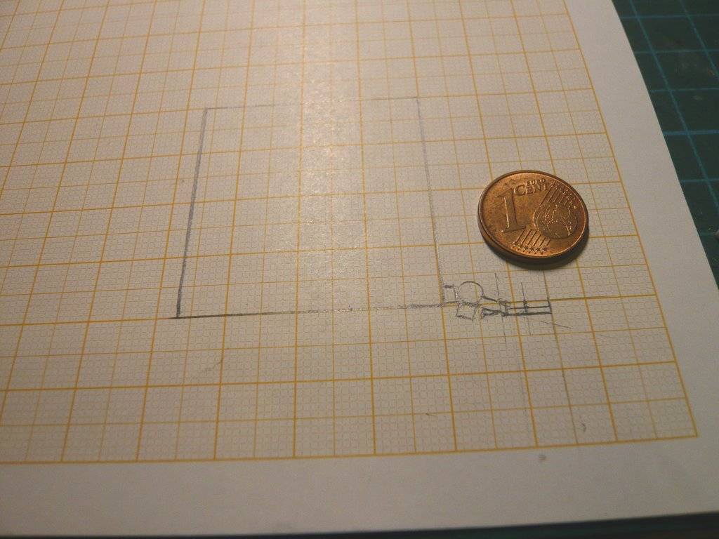
Therefore I have now made a sketch (1:1) of this arrangement, which should make it easier for me to assemble the individual parts. ![]()

In the meantime I have also finished the second “glasses”. ![]()

For the triangular profile (green dimensions) I used an Evergreen Strip (1,5 mm x 1,5 mm), from which I scraped off half of the upper edge with a cutter. ![]() To do this, I held the rod on its edge on a Balsa board in a guide groove, which was not that easy,
To do this, I held the rod on its edge on a Balsa board in a guide groove, which was not that easy, ![]() but certainly doable.
but certainly doable.

And these are all the parts,

that I now just have to skillfully glue together. ![]()
![]()
8 Likes
Hello everybody,
well, that’s easier said than done, since these tiny things are difficult to handle, and gluing them requires precise positioning and a secure hold. ![]()
During gluing the rounded block with the hinge roll that was still relatively easy because the angle provided sufficient support and the positioning was clear from the sketch.
The difficulty generally lies in grasping and holding the parts securely in a suitable pair of tweezers during dabbing the glued area with a tiny droplet of glue at the acupuncture needle, and following placing it onto the roll with a steady hand so that the part cannot jump away, which can happen the smaller the parts become. ![]()

Depending on the adhesive used, there is usually some time to slightly adjust the fit of the parts.


The next step was to connect these assemblies together, for which I came up with the following handling support. ![]()
In order to be able to glue this bizarre, unwieldy Thruster assembly to the hinge roll via the coupling link, an Evergreen H profile (1,5 mm x 1,5 mm), I glued a longer holding bar (0,4 mm x 0,7 mm) into the underside of the H profile. ![]()

This served as a handle for all further assembly steps, onto which the Thruster assembly could also be glued after it had been slightly bevelled according to the sketch.

To do this, the holding bar was fixed to a ruler, after which the Thruster assembly was glued onto the bar and aligned. ![]()


Then the triangular profiles were glued under the slanted H profiles,

for what they were fixed to a stop.

But now those tiny things on the thrusters were still missing that one can see in this image, possibly small cameras, or whatever. ![]()

And these were small stubs in 1:160 cut from an Evergreen profile (0,5 mm x 0,5 mm x 2 mm), which I colored half black, for what one could just hold them in tweezers. ![]()


In order to glue these stubs, the Thruster assembly had to be skillfully fixed so that I could first glue one stub to the rear Thruster, which was quite stressful but fortunately worked right away. ![]()

To glue the stub onto the front Thruster, the assembly had to be fixed rotated by 180°, ![]()

with which this Thruster assembly could be glued to the hinge roll.


This would complete this Thruster and the holding bar could be separated, but I will wait to do that until I have glued it to the Spacecraft, as I want to finish the second Thruster first. ![]()
![]()
8 Likes

Thanks Tim for your nice feedback,
which looks like you are speechless, and/or a little bit overwhelmed … ![]()
But maybe I’m wrong too. ![]()
![]()
1 Like
Nope …you are spot on… insane detailing and now my eyes are worse than ever just thinking about it !!
2 Likes
Hi John,
OMG, you are only looking at the huge macro images, what can I say? ![]()
I need my headset magnifier for that. ![]()
![]()
2 Likes
Hello everybody,
always slowly, first the Thruster assembly must be glued to the hinge roll, whereby again a stop for an exact alignment is important. ![]()
But as one can see in this image,

the arrangement does not yet match the sketch, since the rounded part under the roll must not lie flat.
Therefore, I placed a suitable rod underneath to compensate for the height (2 mm), after which the fitting was perfect and both assemblies could be glued together. ![]()

After aligning and fixing the holding bar, the adhesive point on the top was reinforced again for safety reasons. The first [color=blue]Thruster[/color] is now complete, although the holding bar will remain until the complete thruster will be glued to the probe.

Then the two small cameras were glued onto the other thruster one after the other,


and both assemblies were glued together. ![]()


And since the Thrusters were only ever to see up close, I wanted to see how the thruster would look like at the space probe wall. ![]()
And now one can see how small the whole assembly is and that some details can no longer be seen with the naked eye. ![]()


But I know they are still there. ![]()
![]()
6 Likes
Looking good and a nice fix to get it in the right position.
2 Likes
Thanks John for staying tuned. Let’s go on after a little break. ![]()
![]()
1 Like
Hello friends,
well, it’s been a while since my last post, so it’s not easy to pick up the thread again, as I first have to re-imagine what was going on back then and read up on everything I was doing back then. ![]()

After successfully scratching the two thruster assemblies, I have to return to the three-sided rods system with its blankets that I have been tinkering with for a long time. ![]()

Therefore a quick jump back to my Reply #54 from August last year, as I want to use my tried and tested tape technique again. ![]()
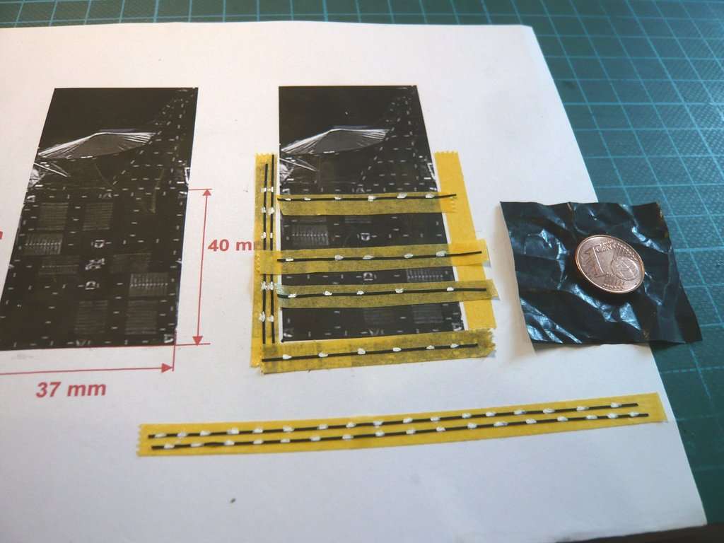
Unfortunately, I had to order new tape because I must have misplaced my old roll and couldn’t find it anymore. ![]()
It took a while until I found the tape Hasegawa TL17 masking tape 0,5 mm x 16 m again at a Japanese dealer (BanzaiHobby). ![]()

But it was a costly affair, I can tell you. ![]()
Tape: 792 Yen x 0,0061 € = 4,83 €
Shipping: 3.150 Yen = 19,22 € Okay, that was the price for delivery in 3-4 days!
Total: 3.942 Yen = 24 € ![]()
And when the package finally arrived, I still had to pay 12,10 € for DHL customs/import duties + flat rate expenses, what an expensive fun! ![]()
So again black tape strips on the template were glued onto a normal tape,

and then with the white Acrylic-Marker short dabs for the markings above are applied. ![]()

And for the following marking rows the same procedure.

Slowly one gets back in. ![]()

I can now stick these strips onto the black blanket foil.

At least a start has been made. ![]()
![]()
3 Likes
Hello my true friends,
let’s finally move on to the blankets. ![]()
In the meantime, I have found my half-used roll of Hasegawa TL17 masking tape 0,5 mm x 16 m again; it had only been put aside well. ![]()
So, in the tried and tested way, short parts of the tape strips were marked with the white Acrylic marker, as one can see on the template and stuck step by step onto the blanket foil.
First the vertical and the horizontal strips,


and then the two diagonal strips.


Now all that’s missing are the two side stripes on the edges.

And with that, the back is finished, and we can move on to the two sides of the blanket. ![]()

It’s quite a fiddly job, and requires patience, but luckily I have more than enough of that. ![]()
![]()
3 Likes
Hello everybody,
for gluing marked tape strips onto the two side blankets I had to modify my template. ![]()
For this, I first needed a picture of the entire rod system, which I first traced and copied. I’ve then cut out the inner part and placed this template over the blanket foil and fixed it. ![]()

Afterwards, using the same procedure as for the back, I was able to mark the corresponding tape strips for the two side parts using the template of the space probe model’s rod system with the Acrylic marker.
These are the strips for the right side,

and here are the strips for the left side.

And after gluing all the strips, the finished three-sided blanket looks like this. ![]()

Now I just have to figure out how to proceed with it, because I think the inside of the blankets still have marking strips too, but I’ll have to look at some of the original photos first. That was all a while ago. ![]()
![]()
3 Likes