Well, I guess we’re both doing it wrong!
I’ve never used the Vallejo brand of paint, but I like what I see, so far. I’m using it straight out of the bottle.
Thanks!
Well, I guess we’re both doing it wrong!
I’ve never used the Vallejo brand of paint, but I like what I see, so far. I’m using it straight out of the bottle.
Thanks!
Good evening.
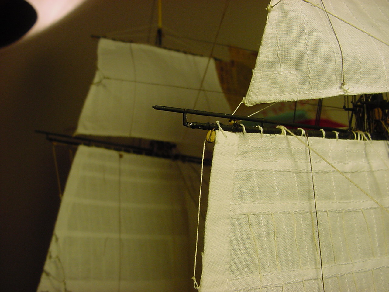
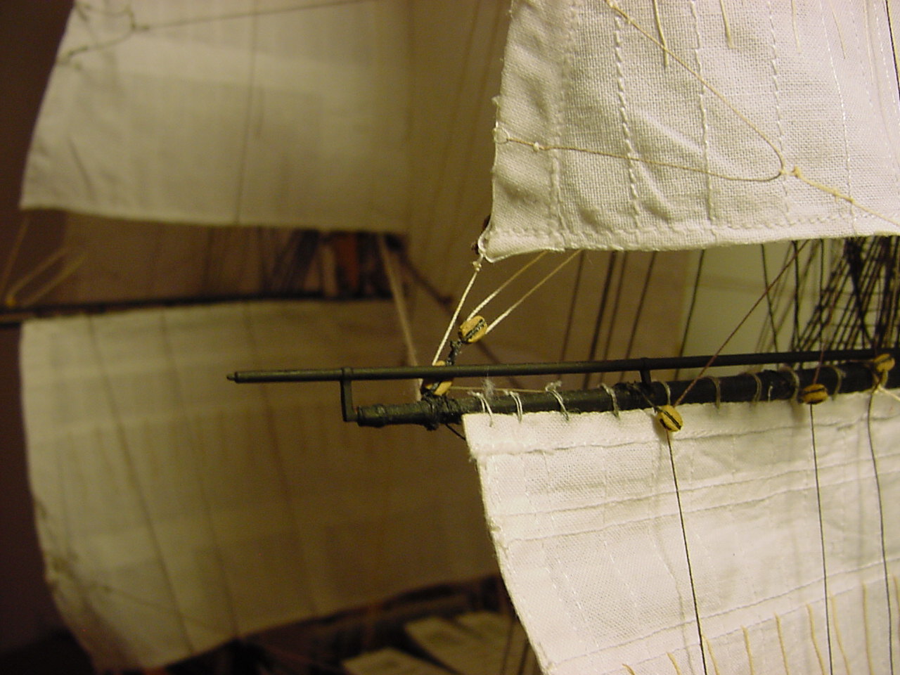
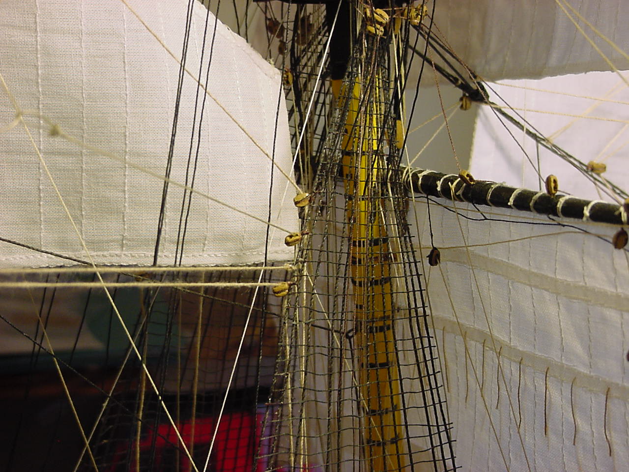
Getting closer to getting done, but things still crop up. The most recent work had me putting in the studding sail booms. In the instructions, you’re supposed to attach these to the yards while building the mast & yards, but I decided to wait until the rigging was more or less completed, as I didn’t want to be banging into the booms, and knocking them off. Besides, I don’t think I would have been able to attach the sails as easily as I did if those studding booms were in the way. So here’s a couple of pix of the booms after I attached them to the yards - the fore top yard, and the fore main yard.
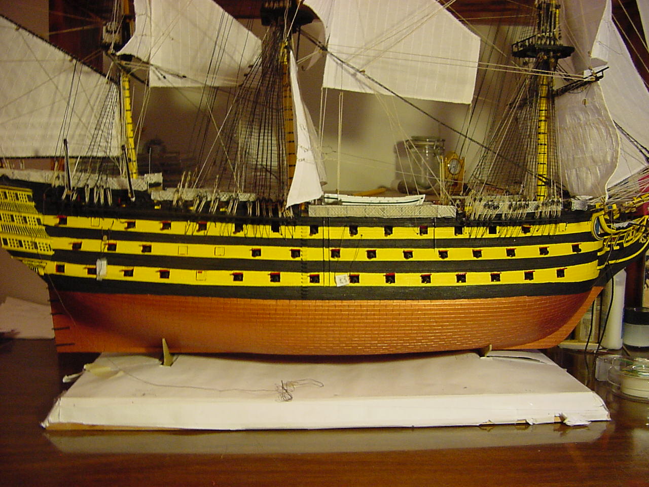
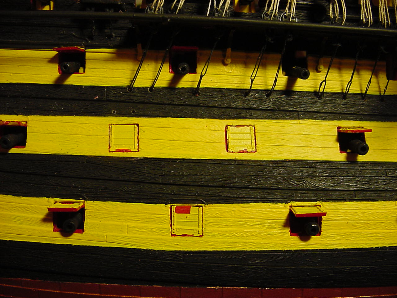
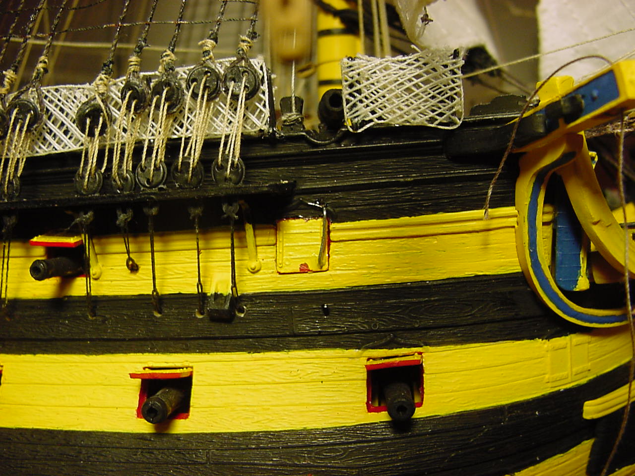
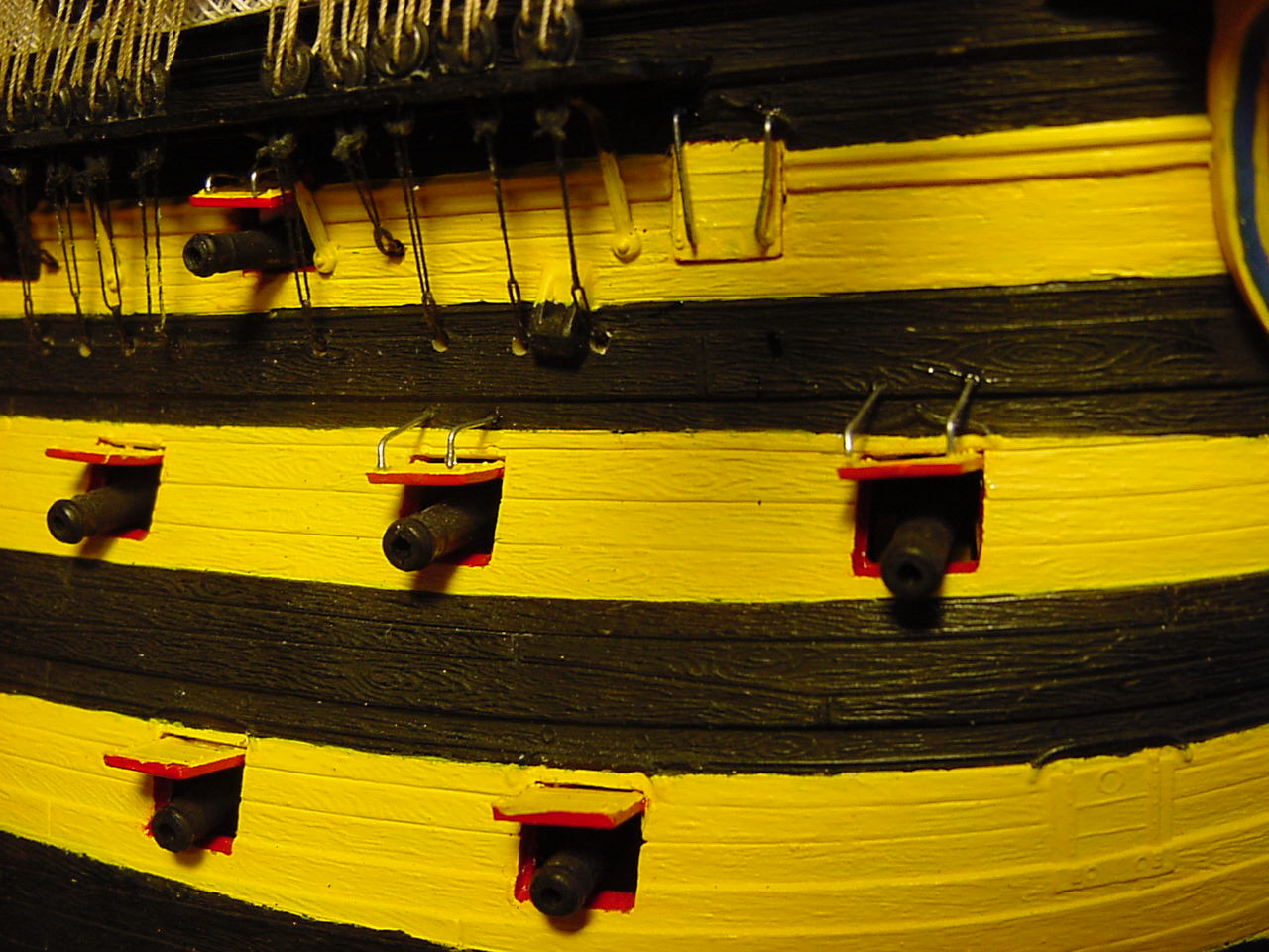
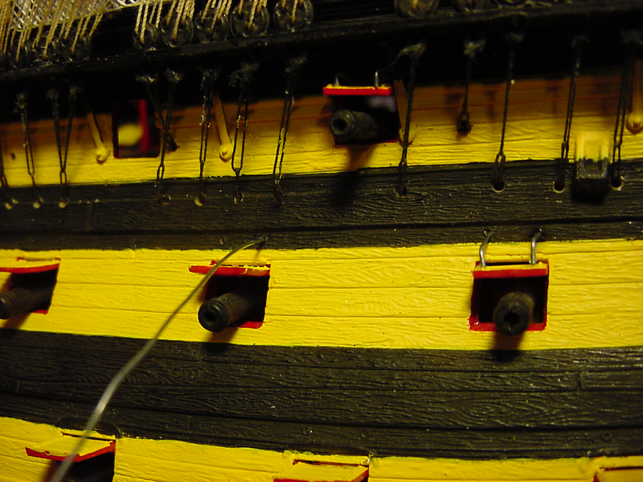
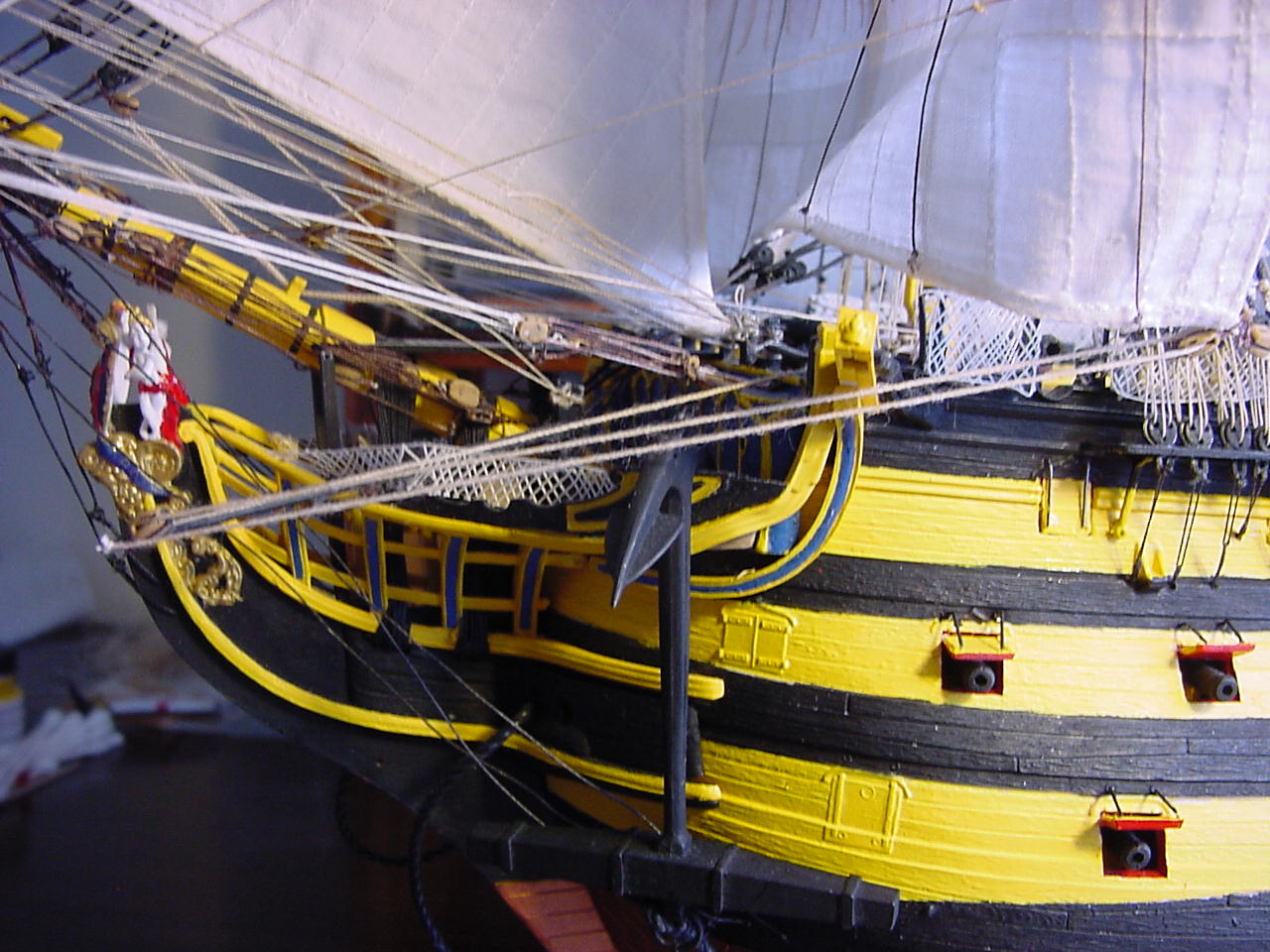
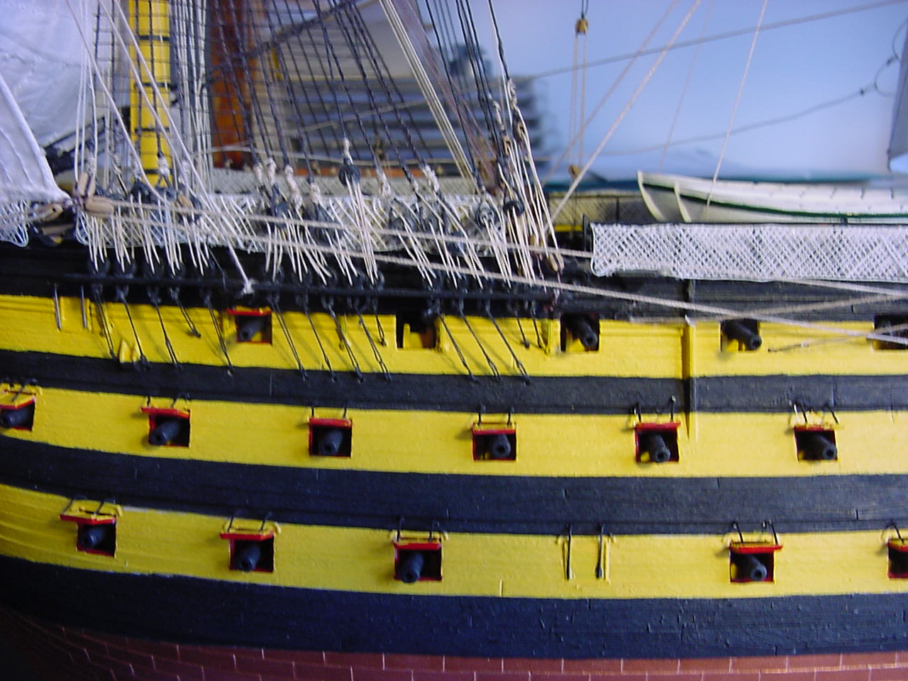
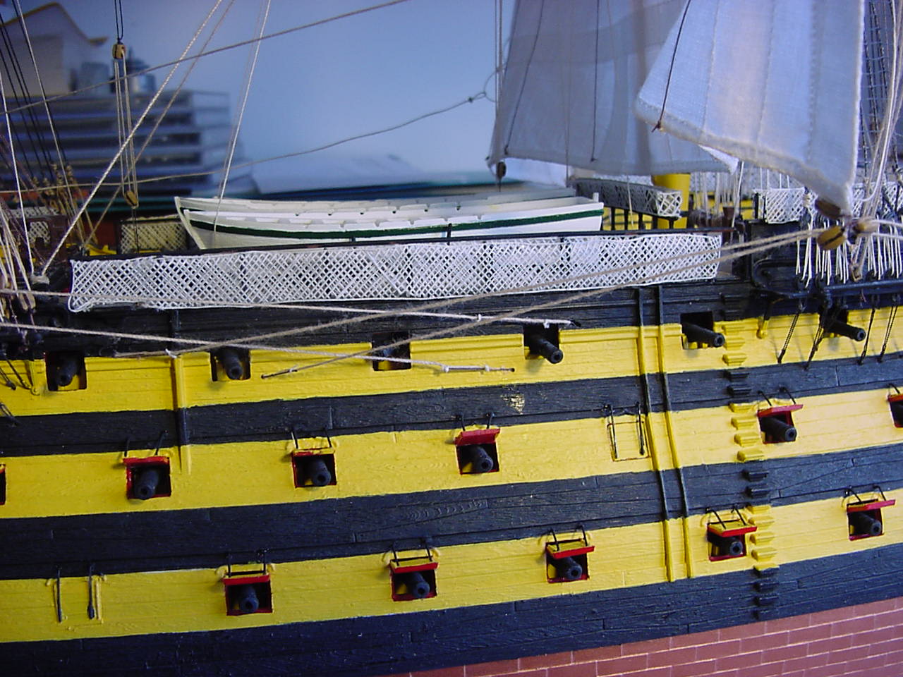
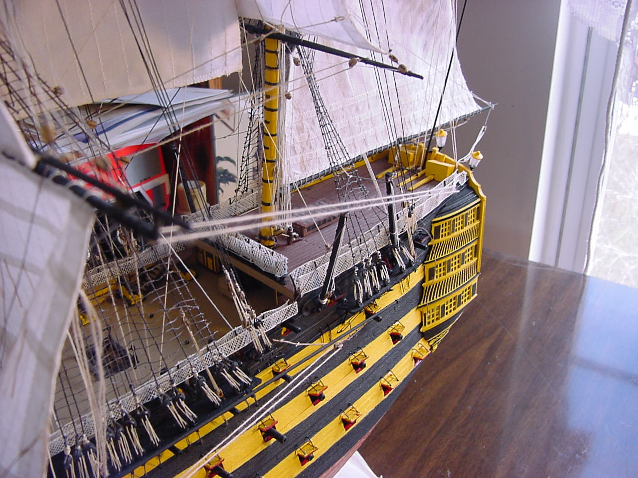
The next effort went into the port lids. I airbrushed the one side of the lids yellow, to match the painting on the hull - but Heller’s instructions says to paint the side facing outwards black. If I had done that, then for those lids that are closed (due to the cannon barrel being lost, or the entire cannon carriage being lost) would have made the hull start to look like a checkerboard pattern. Yikes! Not being overly proficient with an airbrush, I got all the lids to be of a fairly uniform yellow color. Here’s how things look with the lids attached:
Much to my surprise, Heller did a good job of molding a…thing…to which the port lids get attached. I was afraid I’d have to try and do an edge-to-edge kind of attachment, with invariably, inconsistent results. But things turned out pretty good, so far as the attachment goes.
One problem I had, was with the yellow airbrushed paint chipping off when I removed a lid from the sprue:
I’ve already done some touch-up with the yellow, and the results are satisfactory.
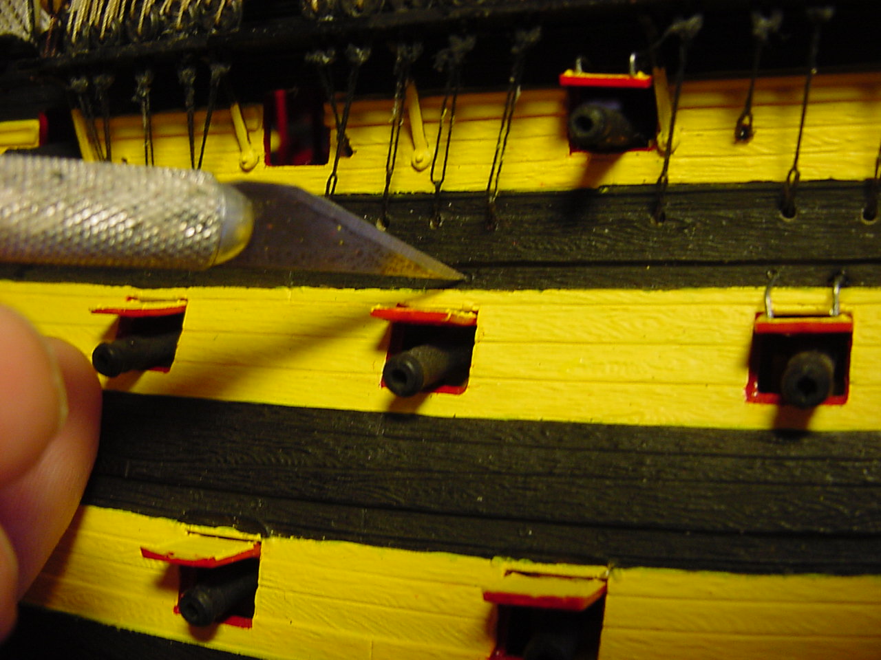
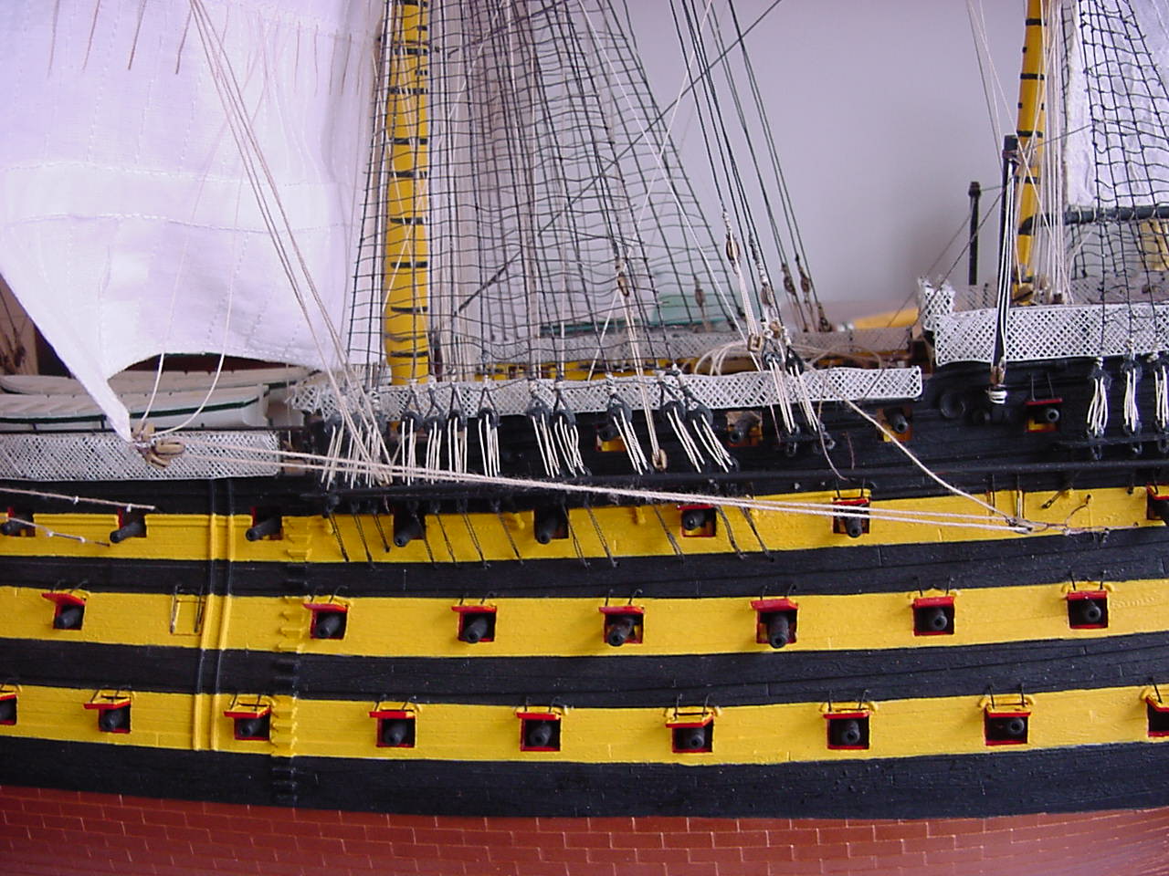
The other thing about the port lids, Heller supplied multiple lengths of wire to mimic port lid lanyards. Just to see how things would look, I shaped and installed one wire. Heller says to paint the lanyards black, but I wasn’t going to do that. However, with the one lanyard installed, the wire looks quite shiny and out of place, so I’ll be painting all those lanyards black after I get them installed.
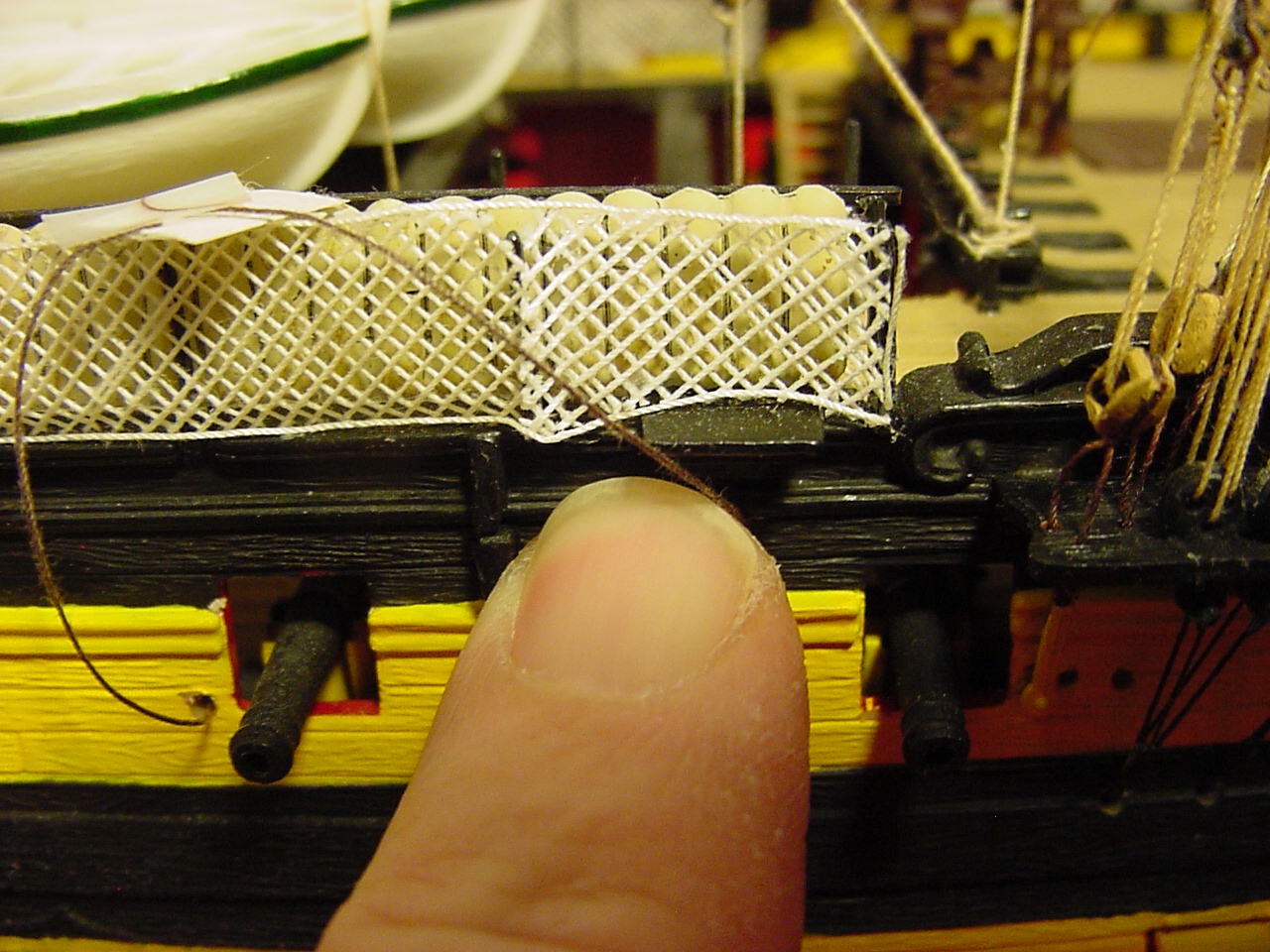
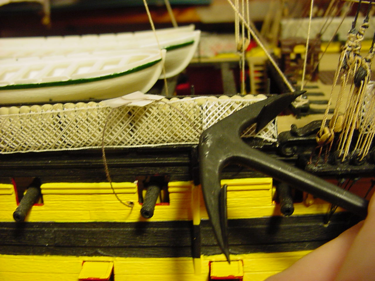
Another thing I’ve noticed is that the spare anchor doesn’t fit. There is a “pad” where the anchor rests, but the space beyond the pad is taken over by the hammocks & netting, not allowing the anchor to sit correctly:
(Oh my God, it’s the finger of doom!!)
And here is how the anchor doesn’t seat correctly:
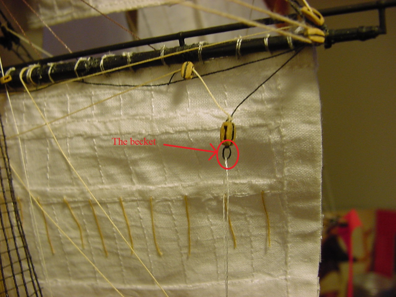
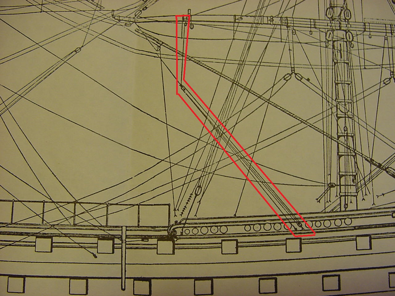
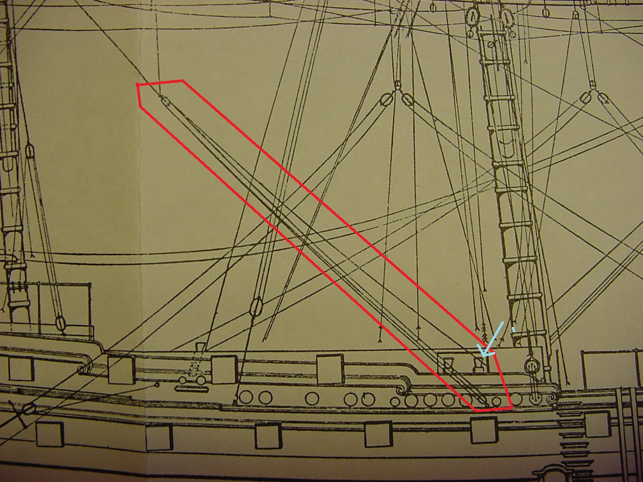
The next two photos are from Longridge’s book, showing the make-up of what is called the tricing lines. This line was used as extra tackle for lifting things. This photo shows the becket on the fore tricing; for some reason, I didn’t put a becket on the main tricing block:
OK, here’s the pix from Longridge’s book:
This is for the main. The light blue arrow seems to show that one end of the tricing line goes either to the bitts, or is passed through the opening of the bitts, and belays somewhere else.
The next two pics are of Heller’s instructions. The first is a close-up of where Heller says this line and tackle should go. However, this nomenclature totally escapes me, and I couldn’t find any corresponding notation in instruction 17, which is the belaying diagram.
And this photo shows Heller’s instruction for the entire tricing line:
Whew!! Writing this post took some doing!
I’m very surprised (and quite pleased) that all my photos for this post are in focus; sometimes, when I use the macro setting, it’s hard to tell if things are in focus or not.
Well, anyway, I think there’s some light at the end of the tunnel, but, with this model, it always seems to be problem after problem. So let’s see, we’re a little more than midway through November - can this beast be finished by New Years? Stay tuned!
Thanks for taking the time to check out this post. And a Happy Thanksgiving to all!
Tim
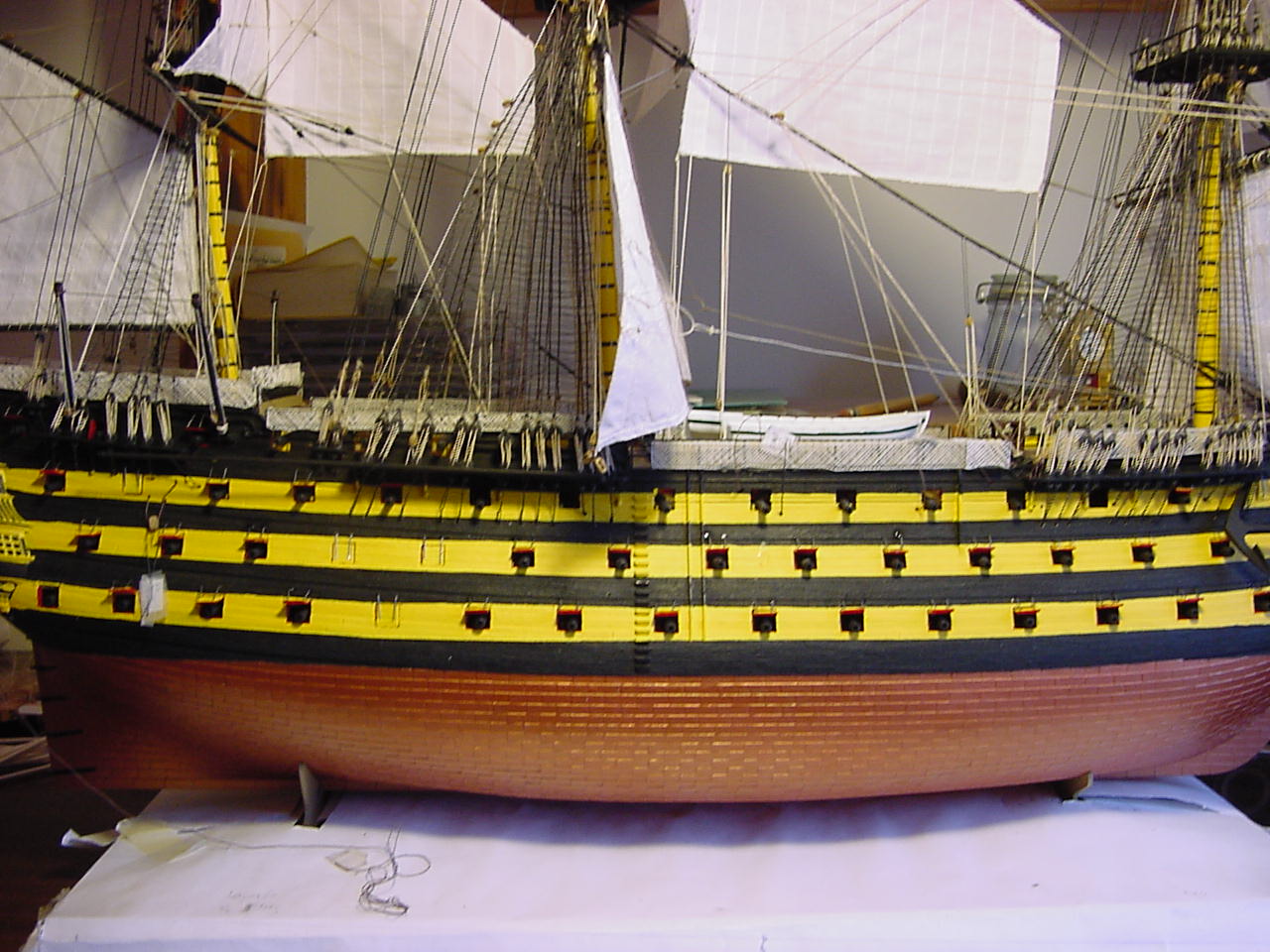
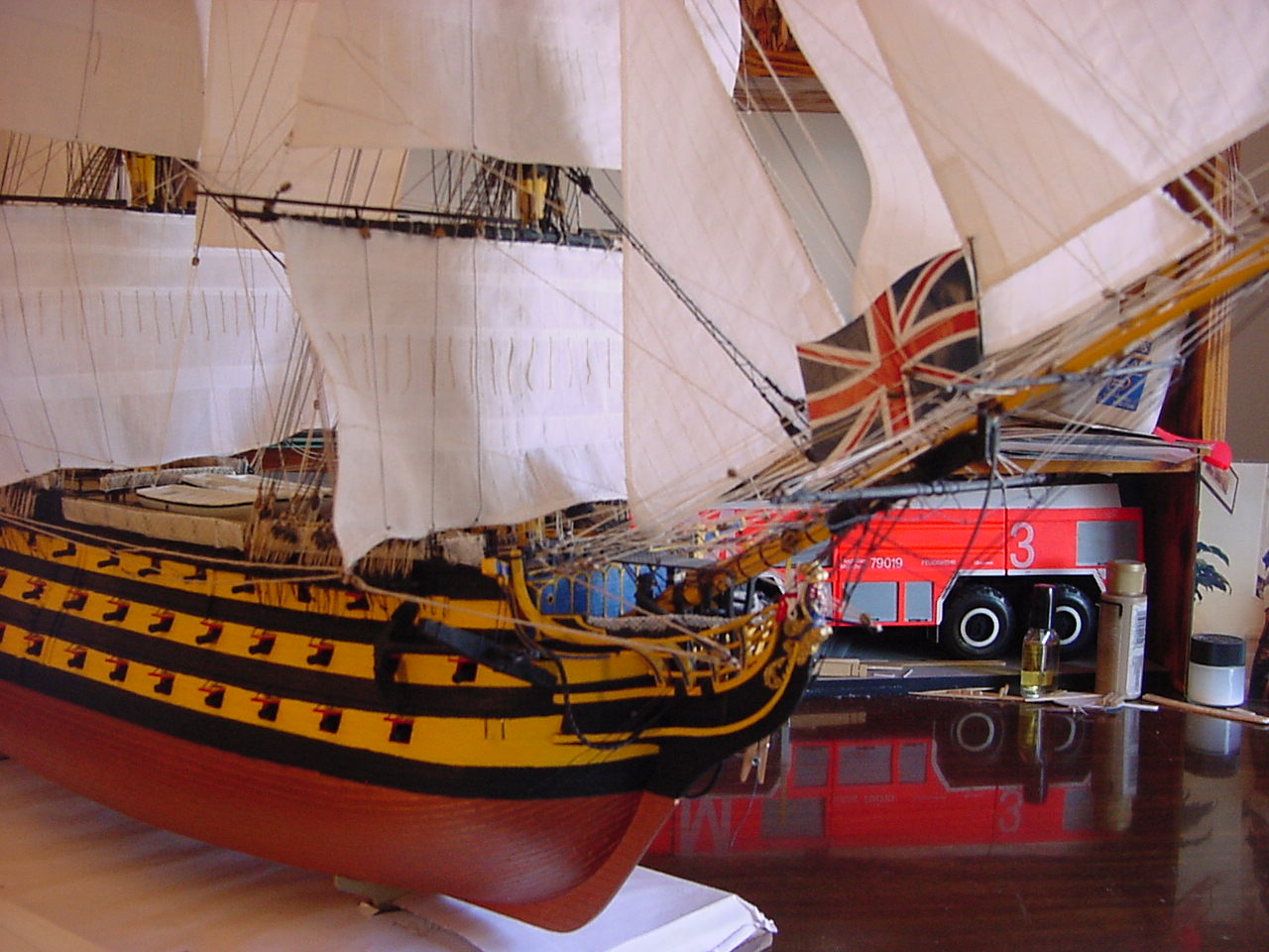
That is looking superb Tim … Loved the broadside picture … Victory is looking close the end … Brilliant work throughout mate ![]()
Thanks, John. I had to take a few steps back to get that broadside picture!
Like many other things, it depends on when you’re portraying the Victory from. If I remember the dates correctly, the stripes and gunport covers were painted the same color up until about September of 1805, when the gunport covers were painted black to suit Nelson’s tastes. The 'Nelson Checquer" became popular through the fleet, although never mandated, until it started dying out toward the end of the Napoleonic period (around the War of 1812), when white paint became cheap enough that white striping began to replace the yellow/buff striping in the Royal Navy and others (for example, the USS Constitution originally had a yellow ochre gundeck stripe, which was replaced by white by 1811).
Thanks for that spot o’knowledge, Sean!
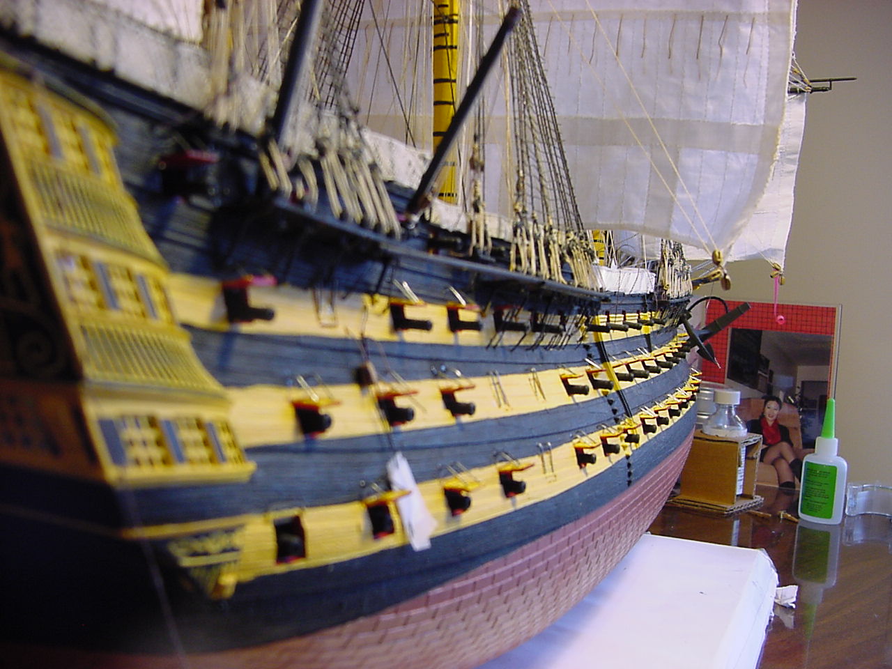
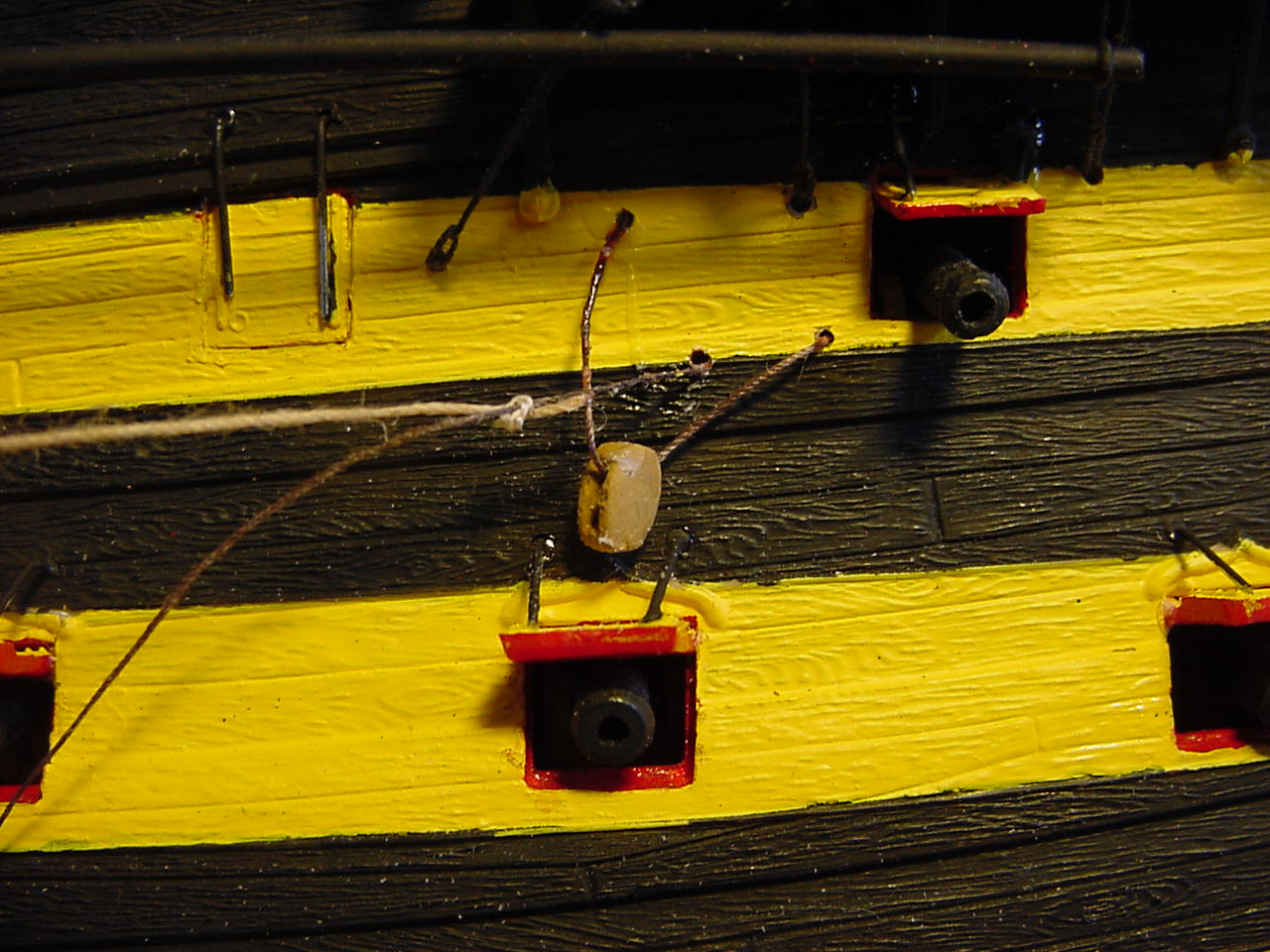
Work is progressing on getting the port lid lanyards in place. Here’s a pic of some of them already installed; at this stage, only 168 more to go!
I discovered that it might be easier to get these little pieces in place, by drilling out the corresponding hole in the hull - that allows for easier locating of the lanyard in the hull, plus it gives me a better surface in which to glue the lanyard. Because the hole is a through hole, I can also shift the lanyard in and out from the hull, so that it lines up better on the porthole lid.
And this last photo shows a length of the metal wire stuck in the hole I just drilled.
For reference, I think I’m using a number 80 drill bit to drill out the holes.
Since it’s supposed to rain tomorrow, I guess I’ll be inside cutting and installing lanyards. For what it’s worth, the length of the lanyard is about 10 mm.
Cheers!
Hey Tim,
great progress and fantastic work! Your Victory keeps to amaze, as does your patience and dedication!
Light at the end of the tunnel - sounds great! This will be one outstanding model!
Looking forward to your progress, and a possible commissioning by the end of this year!
Cheers
Jan
Well there’s a Christmas present that’s been worth the effort… My fingers are crossed for you Tim ![]()
Well Jan, that light might have gotten just a bit dimmer today. I managed to have one of the studding sail booms get knocked - I don’t think there’s any real damage, will just need to cement the part back in place. Keep your fingers crossed!!
Russell, thanks for the encouragement - but let’s not put the cart before the horse! ![]()
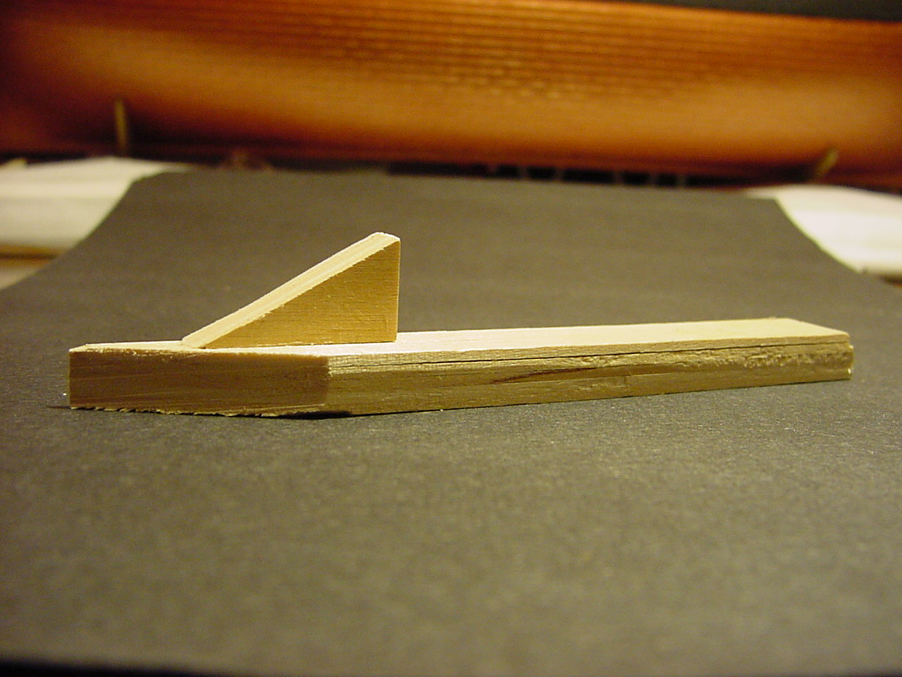
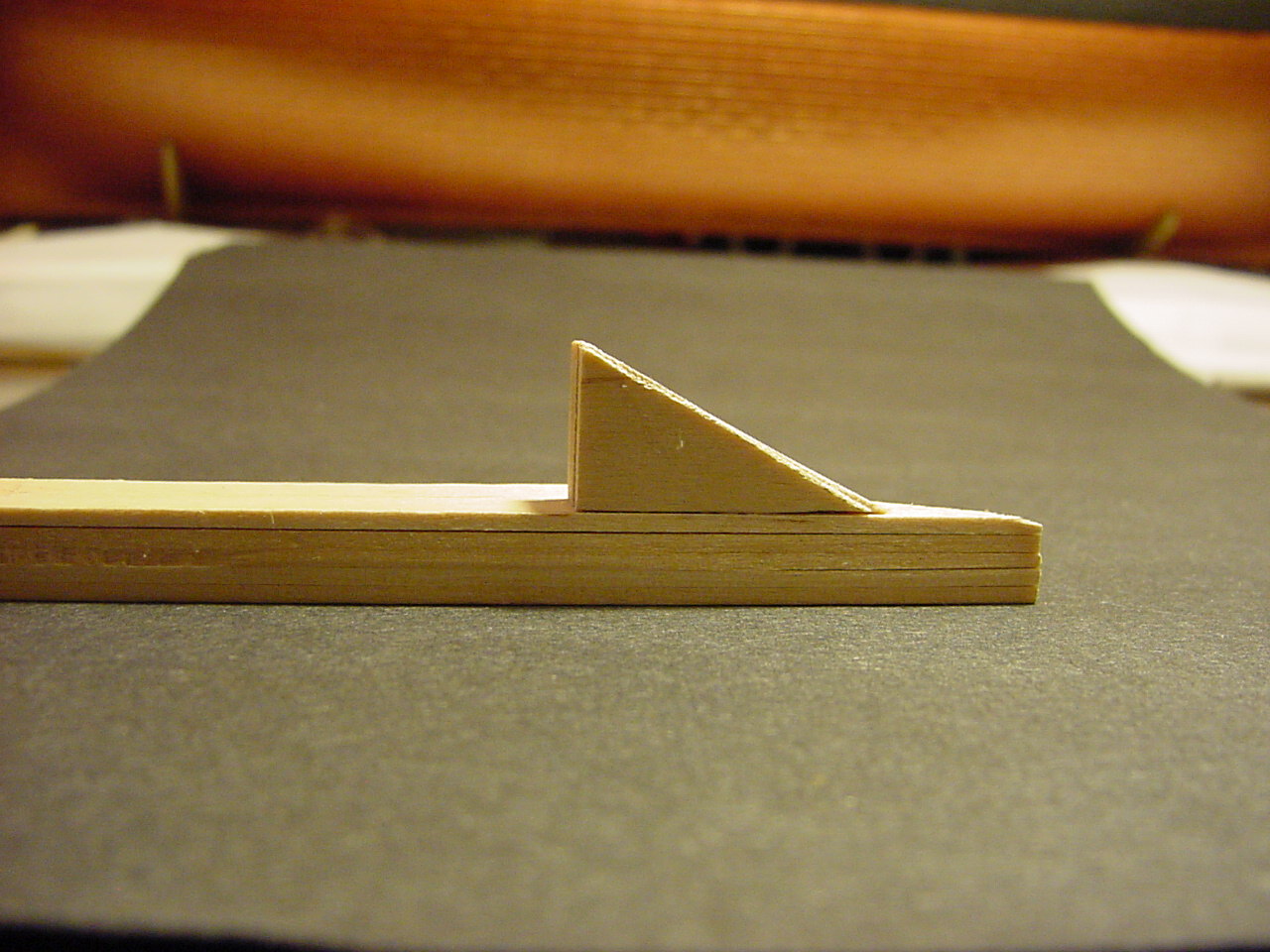
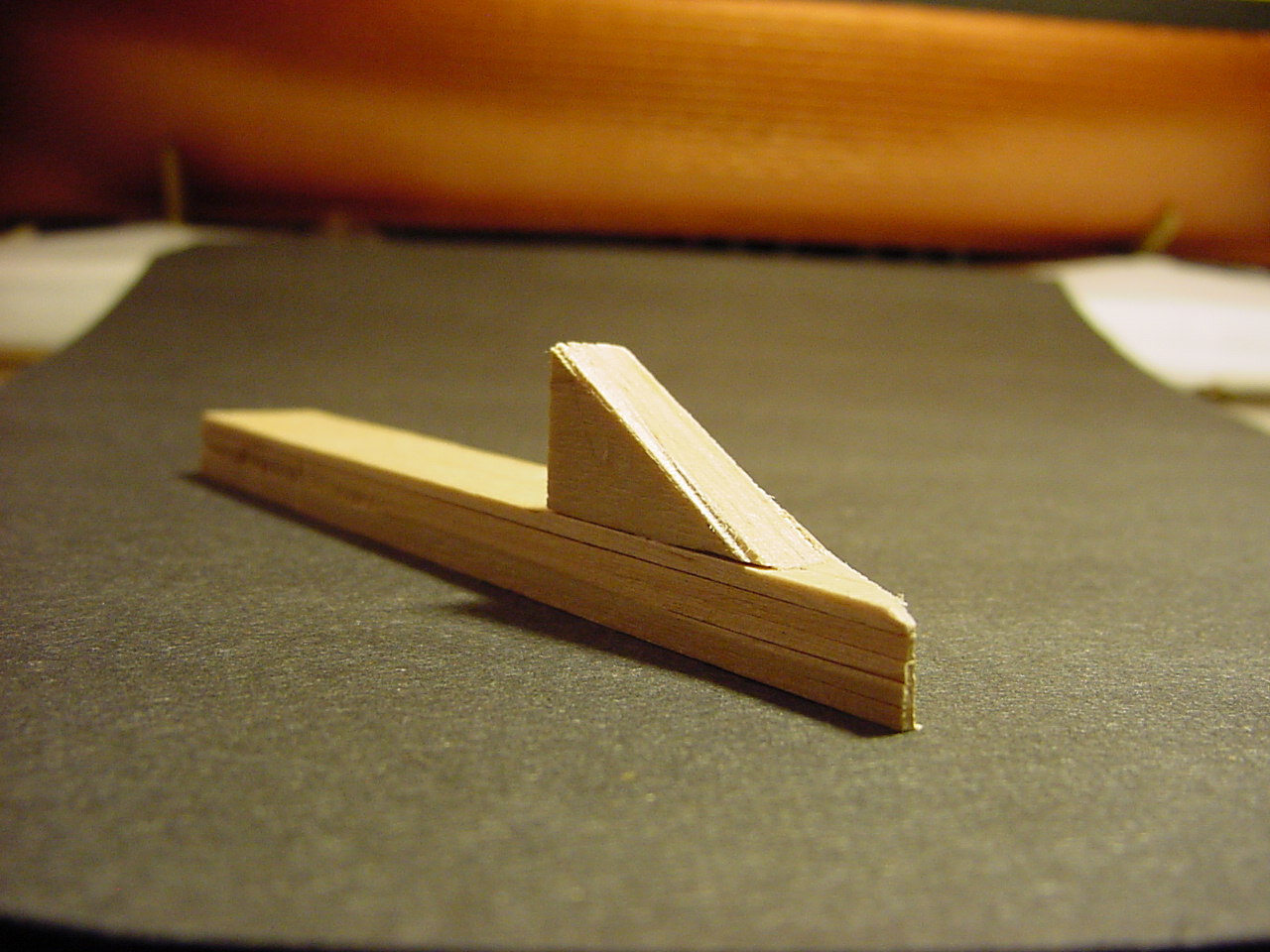
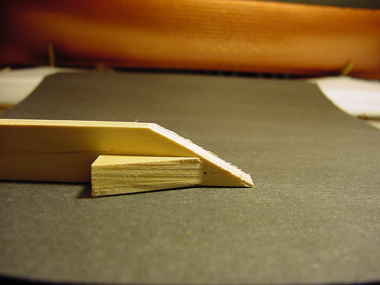
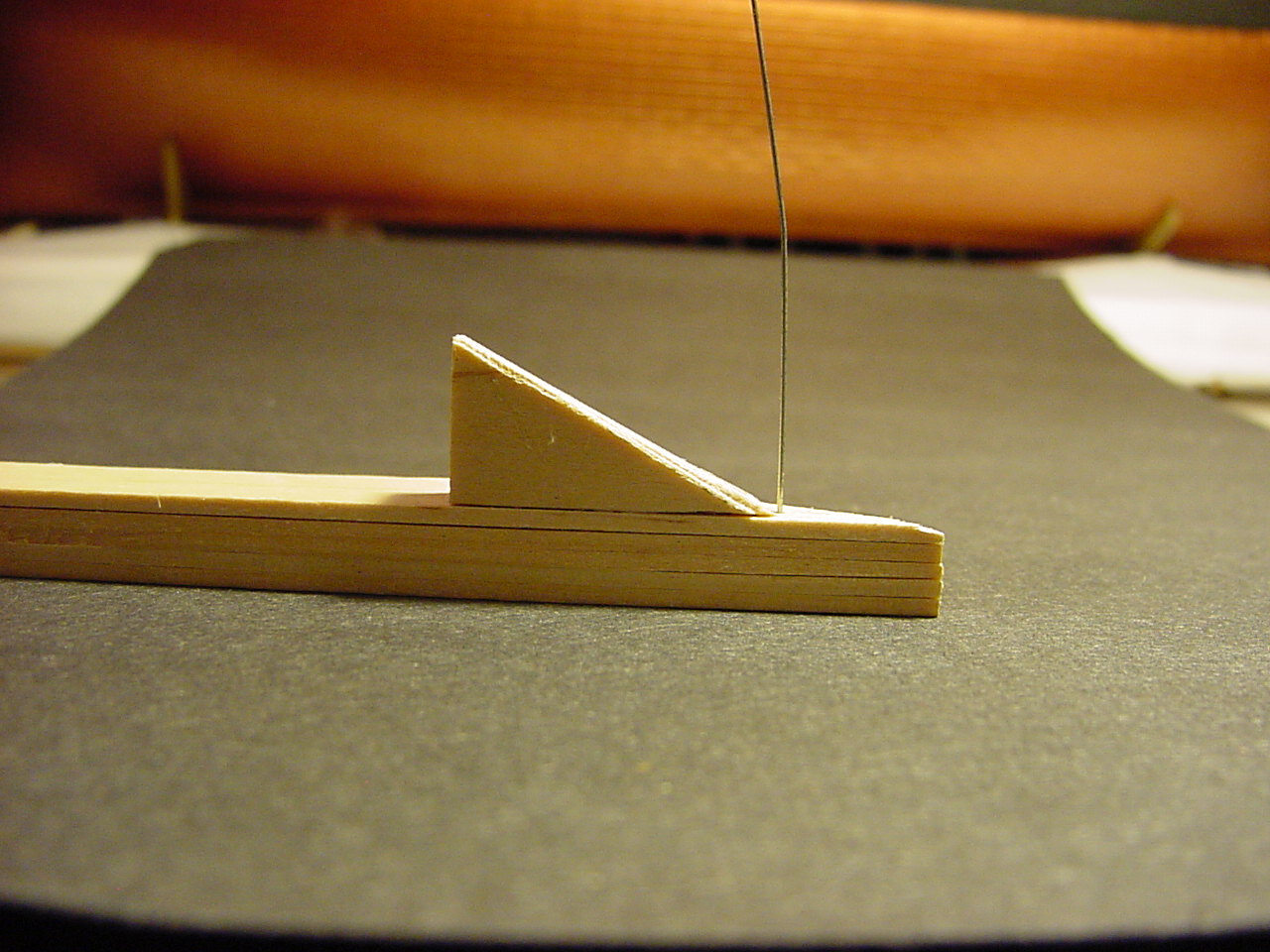
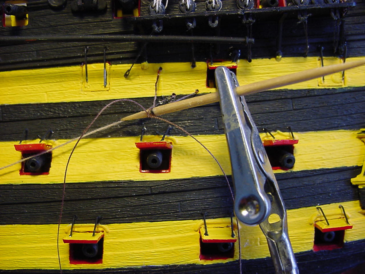
Well, I got to thinking about the wire bending I have to do for those port lid lanyards, and how to keep a consistent look on them. So, I came up with an idea for making a bending jig. Measuring the height of the holes above the port lid (4 mm) and the depth of the port lid from the hull out to where the molded holes are on the lids (7 mm), this translates into an ability to figure out the tangent (the rise over the run, in this case, 4 divided by 7) of the angle. The tangent works out to roughly 0.577 which, when looking up in a trigonometric table, gives us an angle of 30 degrees.
So once I got the numbers worked out, I glued up several large craft sticks (they used to be called tongue depressors), smoothed the edges, then cut a piece away for the angle. Hopefully the pictures show all this much better than I can write it.
The hole is 2 mm deep.
You lost me at “trigonometric table” … but its a very clever and sensible idea ![]()
![]()
Don’t feel bad - it took me a while to spell “trigonometric table”! I’ve already given the jig a whirl - seems to be doing fine.
Well, to continue where I left off:
Here’s some pictures with the port lids installed:
This picture just shows the fore yard studding sail boom:
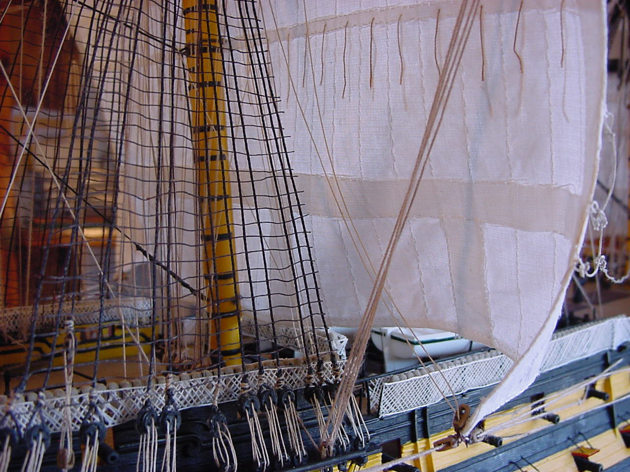
The next picture shows some blocks attached to the main shrouds. See, I was doing quite well with all the rigging, until I got to this point (attaching the blocks to the shrouds). So I had to stop the rigging, and start getting the shrouds installed. So then, after that, I was able to return to the rigging, and get these lines installed. I think the top two lines are mizzen sail bowlines, and the lowest one is the mizzen yard brace. These lines are also present on the port side.
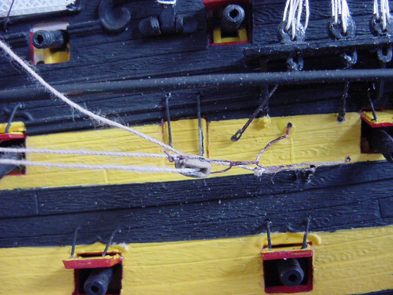
The next couple of photos are about how I initially attached the mainsail sheet block to the hull, and how I went about “fixing” it. When I first started this model, I wasn’t sure about some blocks were to be attached to the ship. So I just used one of the sheave holes to run a line through, and attached the line to the inside of the hull, as per instructions. However, over time, I kept telling myself, “this isn’t going to work”. It wasn’t until I came up with a method of how to get a block attached to the ship, that I realized I’d have to re-vamp the block in question. Here is the graphic version of what was happening:
This first pic is how I interpreted Heller’s instructions for the mainsail sheet block. The line going through the sheave hole shouldn’t be there.
To make this correct, I put a becket around the thread:
The two threads that are emanating from the toothpick will wrap around the block:
And that’s that!
Now for the last bit of rigging:
The fore tack:
The fore sheet:
The main tack, and then the main sheet:
The main course (or yard) brace:
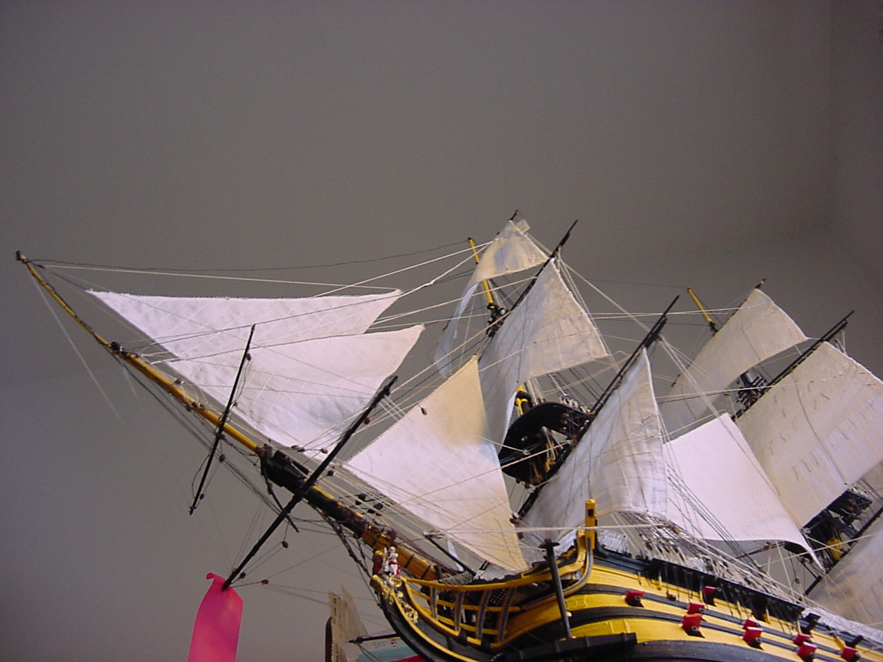
For grins, I took this next photo laying on the floor. I call it “Looking up”.
Once I installed the sheet lines on the fore and mainsails, it caused the clew lines to go slack. The clew line runs from the corner of the sail, up and to the left.
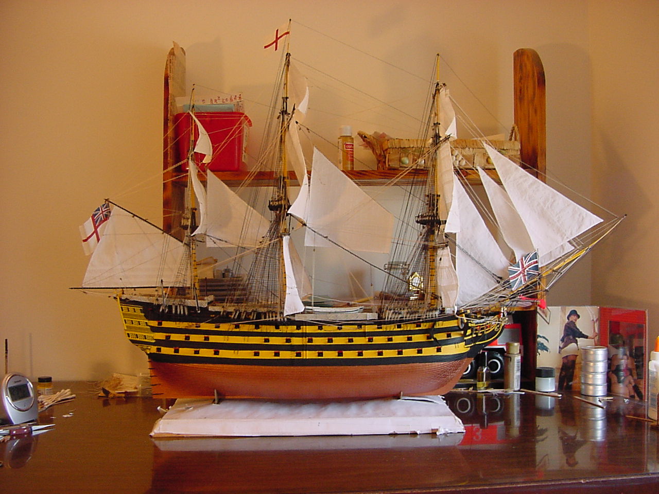
So here’s the finished product, with the flags attached. There was another flag (more like a pennant) that went on the mainmast, but it didn’t fit between the rigging, so I decided not to muck around trying to get it to fit.
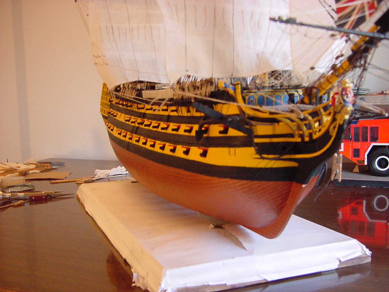
A bow shot:
And looking down the length of the hull:
Lately, I’ve been viewing Victory from the aft end, looking down towards the bow. They must have had at least 2, if not 3 or 4, sailors positioned down the length of the ship, to relay commands/information to the crew that might have been stationed near the foremast, or the bow.
So now that construction is complete, I’m thinking, just for giggles and grins, to try and gather up all my notes & drawings, put them all on the floor, and take a picture of them. Just to give any prospective builders what it took me to figure this thing out!
I guess the next post(s) will be about building a display case, and where to put this thing when the case is done. I just noticed in my pictures, that the “cradles” holding the ship to the plinth (Heller’s word) need painting, as well as the plastic nameplate. I might go to the craft stores and see if maybe they could replicate the nameplate, but in brass or bronze.
I’ve cleaned up my work table of all the tools and odds and ends I’ve used - I even dusted! Now, I have to figure out where to store all the leftover paints I have.
Thanks to everyone who has stayed with this blog, and given me your compliments and encouragement. Of course, there are some things that aren’t perfect, but as my wife used to say, “I know your ability”.
Thanks again!
Tim
Well done that man. What a really epic build …so much to look at and take in.
The detailing is at the next level and that all gets enhanced by the great paint finish… There’s something about that scheme of the yellow and black that just looks right …
The rigging … Well that still blows me away, and combined with the blocks and the gun ports and their lowering mechanisms… Genius stuff … Victory looks superb Tim ![]()
Awesome, and I mean AWESOME! You have turned a good kit into a work of art.
Very, very well done sir!
![]()
![]()
![]()
Superb, brilliant & ample proof model-making can be an art-form. Scary too, until it’s safely in the display box I’d lock the room! Wouldn’t mind seeing a few more looking-up shots ![]()
Most excellent work Tim!
Really admire your persistence and determination to get this beast of a kit built!
And what an amazing model of the mighty Victory you have created! Congratulations!!! ![]()
![]()
![]()
Thank you, gentlemen!
Tim M., I’ll try to figure out some good looking-up shots - stay tuned!
Hey Tim,
apologies for my delayed reply, real life kept me off workbench and even MSW for most…
What an endeavor!
Congratulations on commissioning your HMS Victory! Wow, she looks splendid! And knowing, how much work and dedication you invested - just your seemingly endless fight with the rigging…
Great job - and please, share some more pictures of your beauty!
Cheers
Jan
Hiya Jan!!
Thanks for your words. When are you going to start your build of HMS Victory? ![]() You know, she’s not really complete - I still have to attach the rudder and trim a few other odds and ends.
You know, she’s not really complete - I still have to attach the rudder and trim a few other odds and ends.
I’ll get some more photos soon, so stick around!