Does a torsion bar suspension, such as found on a Panzer III or Panther tank, require large diameter road wheels?
In the near future, I want to scratch build an imaginary German tank circa World War II. Available supplies include some Panzer III swing arms, many Panzer IV road wheels, and many Panther tank swing arms. Panzer III, Panther, and modern tanks with a torsion bar suspension all have large diameter road wheels. Obviously, this increases ride height and leaves enough space in the hull for the torsion bars. I am curious if a torsion bar suspension would work with small diameter road wheels. No vehicle known to me works as described.
The smaller the wheel, means a lower sitting tank, or the road wheel arm is at a downward angle or both.
Think if you used a go-cart sized wheel and the road wheel arm was horizontal then the hull bottom would be on the ground. if you used a go cart sized wheel, the angle of the road wheel arm might be angled down 80 degrees to get the hull up higher but you lose your mechanical advantage the arm has for a smooth ride. So the point is small wheels will work up to a point.
Thank you! That is exactly the sort of tank I was hoping to find.
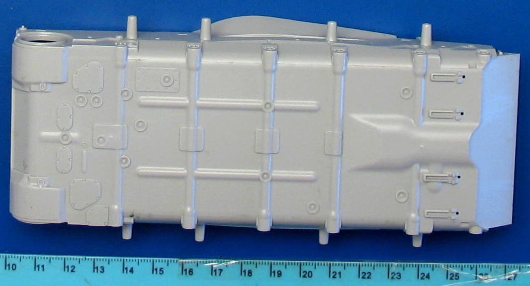
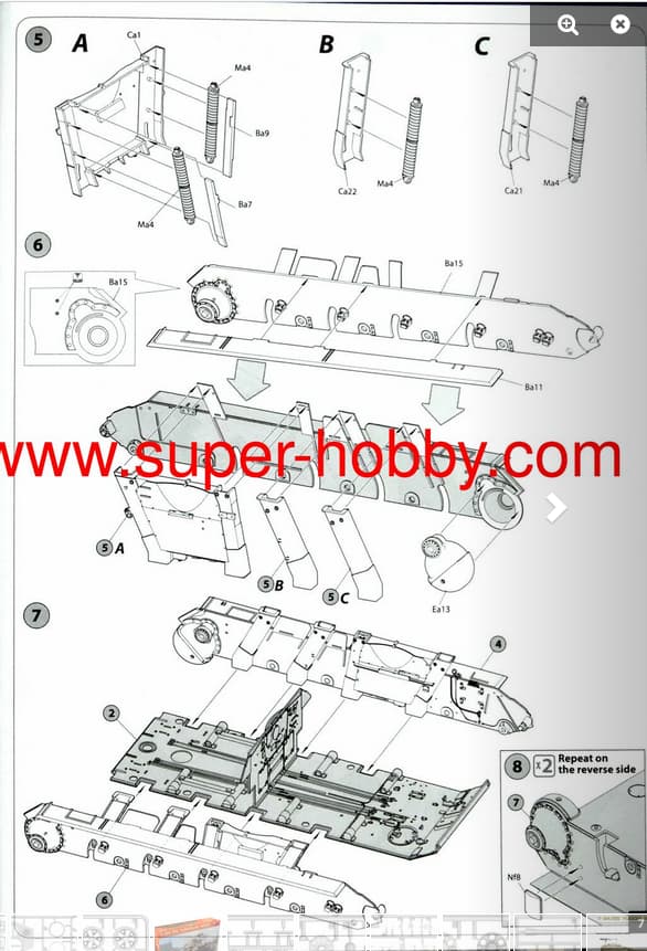
Curiously, on that tank, the torsion bar housings protrude from the belly plate, adding a lot of complexity to the hull design. I wonder why it was done that way.
Thank you! I have not yet built any modern stuff in 1/35. My entire 1/35 collection is only about 20 guns and vehicles. While I have certainly looked at many M113s, BMPs, and M109s, the road wheels never seemed especially small. Yet, when I look at them more closely, their road wheels are on the small side. That’s great. It gives me many design plans to work with.
Thank you! The problem you describe is precisely why I started this thread. For a small road wheel, the arm needs to rotate very far from level and/or be especially long. Another possibility is to connect the arm to vertical shaft that connects to the wheel. That seems bizarre enough that someone probably tried it.
Saving space on the inside? All those torsion bars (2 x the nr of road wheels) crossing the floor of the tank consume a lot of space. The total distance from the ground up to the top of the hull remains the same though …
The belly of Trumpeters T-64B Mod 1984
Complex indeed, not only the torsion bars …
Maybe they had a requirement on the average ground clearance?
Saving weight? A flush hull bottom would require a few extra inches of hull side armour.
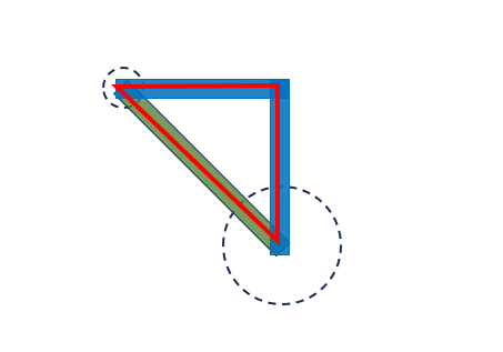
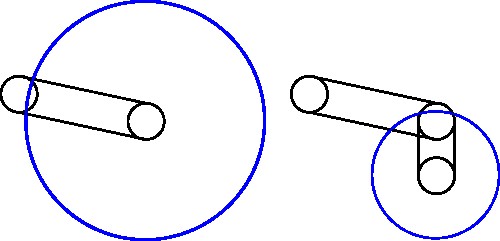
That wouldn’t really change much, the green “arm” or the blue “arm” define the same red triangle
linking the torsion bar/axle to the center of the roadwheel. The arm could be contorted in any number of shapes, curves and angles but the green “arm” is the most efficient solution (performance vs weight)
The T-34 looks, at first glance, as if it has a torsion bar suspension.
Old Tamiya T-34:
I wonder how much room that actually saves. The total height savings cannot exceed two centimeters. If the belly plate was dropped two centimeters, I wonder how much weight the extra side armor would add. American tanks like the M41 have really shallow boat hulls, probably as a defensive measure to protect against mines. Do the torsion bar housings act as stiffening braces and perhaps increase protection against mines?
To my eyes, the road wheels of a Panzer IV look significantly smaller than the road wheels found on any vehicle mentioned so far. Would an angle arm work?
Earlier today, I read up on various suspension systems used by tanks and was reminded that T-34s have Cristie suspensions. I do not have a T-34 in my collection and meant to look up exactly how the Cristie suspension works on that vehicle. Thank you for the information that the springs are hidden inside the hull. I will need to find a good drawing showing exactly how that works.
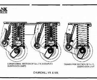
Looking at the drawing in my previous post, I wonder if the wheels are large both to protect the swing arm from damage and to increase tire surface area, making the tires last longer.
Comparing your drawing to mine, I wonder why swing arms are not set at 90 degrees. They always seem to be set at 15 degrees or so. Why is that?
Edit: I wonder if the 15 degree angle is optimum when taking into account the total travel allowed by the torsion bar.
The elbow solution does create a third stress point. Why would anyone want small road wheels? Yet, they are all over the place.
Yes, the solution chosen by the Soviet designers is hard to explain without reading all their design documents.
Angle arm: It still defines the same triangle as the straight arm but with one crucial difference:
There will be tension on the “elbow” which requires a heavier construction to provide the same performance as the straight arm.
Rolling resistance (debris getting in the tracks, hitting a bump so that the wheel most roll uphill or simply resistance in the bearings) will put tension on the “elbow”.
Wheel sizes: Any wheel is able to overcome an obstacle which has a height that is a certain percent of the wheel diameter, small wheels → small obstacles, large wheels → large obstacles.
An off-road car/truck/jeep will climb a curb without issues but try hitting that curb with a shopping trolley …
Wheels on tracked vehicles roll on the insides of the track but debris can get inside the track …
Excavators and bulldozers have small wheels but they move very slow, the wheels are all steel, the whole wheel area is covered which protects the wheels against large rocks, small rocks are simply crushed to dust.
Large wheels have less problems with debris, larger individual contact area with the track but there is more track between each contact area so there is more “unsupported” track which requires a stronger track and higher track tension. Small wheels spread the load better with smaller gaps between road wheel contact points.
The Panther and Tiger got the best of both by having large interleaved road wheels but got problems with mud, ice or both packing solid between the road wheels.
The simple answer is that the road wheel size is a compromise between different requirements, there is not a single “best solution” for all possible requirements and environments.
Swing arm angle.
The torsion bar suspension would become useless if the swing arm pointed straight down (ninety degrees to the horizontal). If the swing arm was horizontal you would need larger road wheels to maintain the ground clearance and that could lead to a non-optimal road wheel size (needs to be large enough while still being small enough, road wheels may need to be replaced using available manpower, a winch and repositionable crane costs weight and space).
Maybe 15 degrees is the optimal angle to meet all requirements, the wheel needs to be able to swing both up and down …
Why indeed …
Are they all over the place?
The T-64 is one example with fairly small road wheels with considerable space between them.
The others mentioned by @HeavyArty have less space between the wheels. I don’t have the dimensions of the T-64 wheels or the others so I can’t compare them.
Another consideration is the geometry. Given that we want the same ride height the smaller road wheel requires a longer arm (straight or not) since the center of the road wheel is closer to the ground. The same weight on each road wheel results in a greater twisting force on the torsion bar which implies a larger/heavier/stronger torsion bar UNLESS the weight is distributed on more wheels = more swing arms = more torsion bars = more torsion bar housings/assemblies. The weight savings from the smaller wheels would be consumed by the increased weights from more wheels and suspensions.
Are there examples of tanks with smallish road wheels and torsion bar suspensions?
Yes.
Were they optimal?
Who cares, they existed, that’s all we need to know.
Can a model builder make his own design to have fun with left over parts?
Of course! The 1:1 world has plenty of examples of failed designs so adding a fictional one will not cause the end of civilization
Have fun with your leftovers
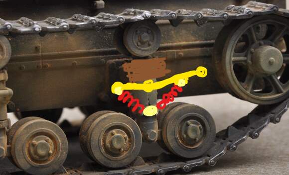
Edit: I just had a bright idea (or maybe totally silly, YMMV …)
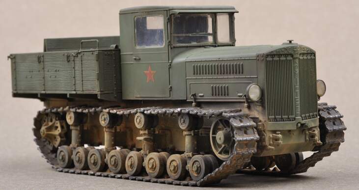
Why not combine the suspension design of the Komintern tractor, Trumpeter 05540:
Ground clearance thanks to the vertical post in the middle of each bogie
Very “unique” visual appearance
The “elbow” between the vertical post and the torsion arm should have some kind of dampening to prevent the vertical post from swinging too freely, springs on front and rear side or some type of oil/gas cylinder. If you use springs the torsion bar needs to extend past the vertical post
General idea: