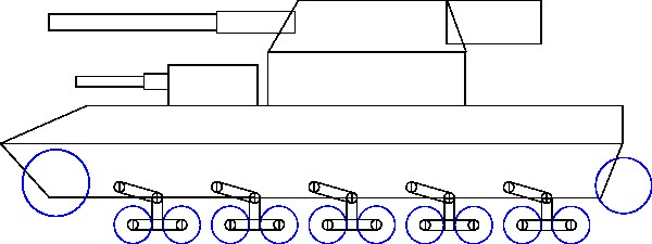
A different approach.

1 Like
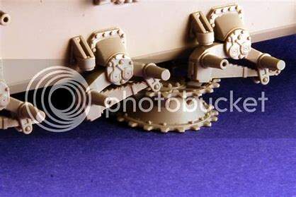
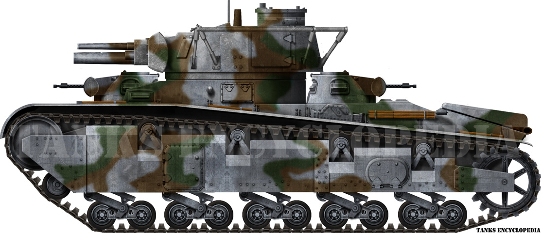
Nice photo. Verifies that they got the symmetry correct on the T64 torsion bars.
Oops. I meant 45 degrees, not 90 degrees.
Are torsion bars set to 45 degrees, but bending to 15 degrees under the weight of the vehicle? If that is the case, removing both wheels in a pair would allow the torsion bar to snap back to rest position–45 degrees. Does that happen? That seems very dangerous for anyone replacing a wheel. If 15 degrees down is the rest position of a torsion bar arm, how come it does not wind upward under the weight of the vehicle? Pictures of tanks hanging from cranes always show the wheels hanging much further down than normal so the unloaded position must be more than 15 degrees.
When I wrote that small road wheels are “all over the place”, it was in reference to older vehicles like the Russian T-26, Chech Panzer 35(t), British Type IV World War I tank, and Russian T-28. As you wrote, the small road wheels distribute vehicle weight very evenly at the expense of suspension travel. Also as you wrote, Panthers and Tigers get the best of both worlds by interleaving road wheels, at the expense of complication and greater maintenance hours. To my knowledge, no vehicle with ‘tiny’ wheels mounts them on torsion bars.
Thank you for linking the Komintern tractor. To my eyes, Russian T-28 tanks use exactly the same suspension system. The T arms and coil springs would be very easy to scratch build. During World War II, did the Germans use anything of native design with an inverted T arm suspension?
Your picture of an inverted T arm attached to a torsion bar swing arm is very interesting. Would it make any sense to have both a coil spring and torsion bar swing arm supporting a single T arm? Early tanks often have very complicated suspension systems.
Edit: E-25 tank destroyers were designed to use a disk spring suspension. Are disk springs comparable to torsion bars? Would it make sense to pair small road wheels on T arms supported by disk springs?
Did American half tracks and Panzer 35(t) tanks use the same kind of suspension bogie?
Am I using the word bogie correctly? I need to look that up. (Bogie, not bogey?)
I wonder if I could scratch build something like that using the bazillion Panzer IV return rollers in my spare parts box.
Edit: Bogie. I now see many early tank suspensions are train suspensions.
I haven’t got the foggiest idea about the “neutral” position of a torsion bar on a tank. As you write it is obviously not the same as the loaded position.
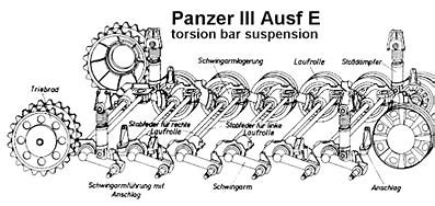
Torsion bar and a pair of wheels?: Torsion bars are usually set up so that one torsion bar serves one swing arm and that swing arm is attached to one wheel. One end of the torsion bar must be firmly attached to the hull of the tank and the other is free to rotate with the swing arm.
Torsion bar suspension usually results in the wheels on opposite sides of the tank being offset against each other. The wheels on one side is further forward than the other side.
If the wheels on opposite sides of the tank are connected to the same torsion bar then the centre of the torsion bar must be attached to the hull bottom. If both ends swing free there will be no spring function, only a steel bar.
Lifting a tank with torsion bar suspension: Same as with any vehicle with some kind of springs, the suspension relaxes until it comes to its “neutral” position or is stopped by some mechanical restriction. On a normal car the shock absorbers sometimes act as the restrainer, on some they have solved it by different means. Some cars/trucks had the unfortunate ability to overextend/overload the suspension so that the wheel became horizontal under the vehicle. Not fun at all …
On a tank with torsion bar the suspension travel can be limited by the track, by shock absorbers or be the torsion bar reaching a small angle below the neutral (the weight of the wheel + the swing arm).
I hope I understood your question correctly.
T-28: Similar but not the same:
Three pairs of small wheels connected to the same rocker arm assembly.
The rocker arm connects two pairs to a third pair (why make it simple when it can be made overcomplicated, sigh …)
I think the German engineers had moved past the overcomplicated designs, the Neubaufahrzeug resembles the T-28 (lots of wheels on vertical springs)
The Pz I also had a complicated design:
Disk springs: A disk spring functions similar to a coil spring (at least when compressed, not sure about pulling apart). Make sense to combine? Why not, if some engineer realised that one of them couldn’t handle the load by itself. It could look odd though …
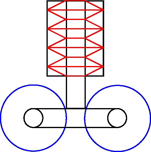
Torsion bar: Rotational
Disk spring: Compression along the centreline
Leaf springs: Bending motion, spring package fixed in the middle or only at one end (basically half a spring pack).
Coil springs Compression and/or extension along the centreline
1 Like
Similar but not exactly the same.
Halftrack:
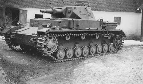
Pz 35(t)
T-26 (suspension originally designed by Vickers, Vickers 6-ton)
1 Like
Don’t forget the Tiger, where the arms pointed backward on one side and forward on the other!!!
Cheers,
M
2 Likes

1 Like
Thank you for the clarifications and all those pictures.
With regards the T-28, I did not know the T bars were supported by leaf springs! I wonder how much travel a leaf spring suspension like that one allows. It only looks like a few inches to me.
I remember reading that disk springs provide a lot more, umm, springiness than coil springs. It makes sense. Despite their small size, they use a lot more metal. The disk springs on an E-25 are very compact. Curiously, E-100s use coil springs. I wonder why German engineers chose not to standardize on a single suspension, and why they chose not to use torsion bars even though Panzer III, Panther, and Tiger suspensions were successful. I wonder if that was an ease of servicing decision. My understanding is that American M4 bogie assemblies were very easy to service and swap around.
Moving on to the American half track, it appears to use volute springs. It is American, after all. The Panzer 35(t) is back to leaf springs. I wonder which has more travel and gives the better ride.
When first contemplating this project, I was going to use leaf springs. Unfortunately, leaf springs are complicated and making 6, 8, or 10 identical sets seems like a difficult goal.
A web site I found lists maximum road wheel travel for a Panther as 510mm versus 100mm for a Panzer IV.
I also just learned there is a relationship between road wheel diameter and resistance to movement. Panthers apparently had very good cross country performance because of their many large, interleaved road wheels.
1 Like
I don’t think I saw it mentioned but the weight of the tank along with its overall dimensions factors into the road wheel size to achieve some sort of ground pressure/ft per square inch ratio voodoo math also. Also tank into count the number of teeth on the drive sprocket along with the dimension (think back to learning gear selections on a 10 speed bike). I understand there’s a sort of formula but honestly I’m no math or engineering guy but there’s a science between the efficiency/rolling resistance/not getting bogged down by too few contact points at work.
2 Likes
Thank you for bringing up those points! I was just reading about rolling resistance.
Rolling resistance and weight definitely constrain my project. I considered making a very long, heavy tank with 12 Panzer IV road wheels on each side. However, I am working with Panzer III drive sprockets. Based on what I currently know, that combination seems unlikely. Maybe I could get away with 10 road wheels.
The soviet T 10 has a long hull and 7 sets of road wheels. There were problems with the hull due to the length and it overall was not considered a success. Hull length and turning radius are directly related.
2 Likes
From that sketch use a Hummel, Elephant ir Nashorn as your reference. Yes, mechanically they were less than ideal but the reference is more applicable.
Maybe one of the vets here know more about that ground pressure formula and theory and can fill in those blanks too.
Weee-eelll “acktschuallly” it is the ratio between length and width. ![]()
Long and narrow has problems turning.
Short and wide has problems going straight.
Long and wide has problems fitting on trains and bridges …
1 Like
I think you could stretch it to 12 (6 pairs). Remember, there is no rule saying that it must be a successful design. Many of the tank designs from the pre-war period were not successful …
1 Like
Gears: Divide the number of teeth on one cog-wheel by the number of teeth on the other to get the gear ratio between those two cog-wheels.
gear ratio = teeth in driven gear/teeth in driver gear
Example: A smaller wheel with 20 teeth drives a larger wheel with 40 teeth. The ratio is thus 2:1, the small wheels turns twice to make the big wheel turn once. Seen from the other direction, big drives small, the ratio would be 1:2.
10-speed bike: Largish cog-wheels by the pedals, small to medium cog wheels on the wheel.
Torque: https://www.youtube.com/watch?v=T99yH_gw3p8&t=9s
(We extend the handle of the wrench with a pipe when the lug nuts on the truck don’t want to move)
The arm between the pedal and the cog-wheels up front gives a lot of torque to turn the front cog-wheels, length of pedal arm versus radius of the cog-wheel. The chain connects the front and rear cog-wheels 1:1 so this can be ignored (yes, there is some friction in the chain but I will ignore that now, just assume a perfect friction free chain …).
The rear cog-wheels also have a radius (torque length) which competes with the radius of the bike wheel. Going uphill we want maximum torque. Smallest wheel up front, i.e. smallest radius to get the best torque ratio from the pedal arm, largest wheel in the back, i.e. longest possible torque arm to compete with the radius of the bike wheel.
The radius of the bike wheel is fixed and the length of the pedal arm is also fixed.
For speed we want the largest wheel up front and the smallest in the back.
Tank (or tracked vehicle): The engine drives the gear box, the shaft going out from the gear box drives the sprocket wheel. The sprocket drives the track and the track is in contact with the ground.
The radius of the sprocket is the torque length which resists movement, the sizes of the gears inside the gear box gives the torque length/lengths that drives the track forward.
The difference between the 10-speed bike and the tank is that the sprocket on the tank is fixed, there is only one cog-wheel which can not be changed while driving. In other words: the cog-wheels on the bike wheel are inside the gear box in the tank, the sprocket teeth on the tank are equivalent to the spokes on the bike wheel.
To get the most torque pulling the track forward we need to reduce the torgue length for the sprocket (smaller wheel) and have longer torque length in the gear box. A large sprocket wheel requires more and/or larger cog wheels in the gear box and/or a stronger engine with more torque. This requires heavier axles and drives up the weight and size.
Heavy tank with weak engine would use a small sprocket and move slowly.
Light tank with powerful engine would use a large sprocket and move faster.
Optimising all those combinations is a job for a transmission engineer (which I am not …)
1 Like
Thank you for yet more useful information!
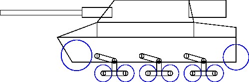
Even with the larger road wheels, the last sketch probably looks too much like a German Neubaufahrzeug or Russian T-28.
Short and wide might be fun, like a Panzer I F or Panzer II J.
1 Like
Tanks like fighter planes, battleships, jetliners etc… move toward a common design as engineers discover the most efficient way of doing things. Eventually they start looking alike.
3 Likes