Dragon T28 Super Heavy tank build log

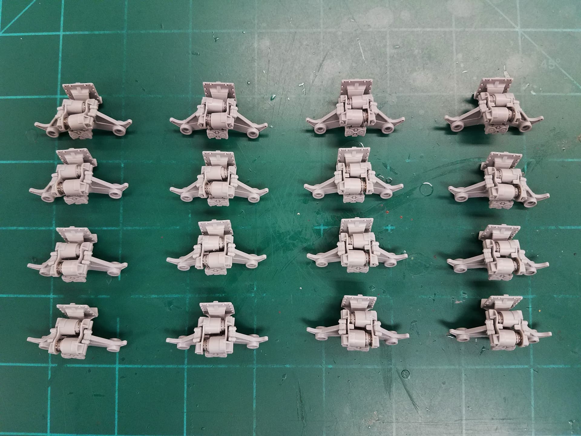
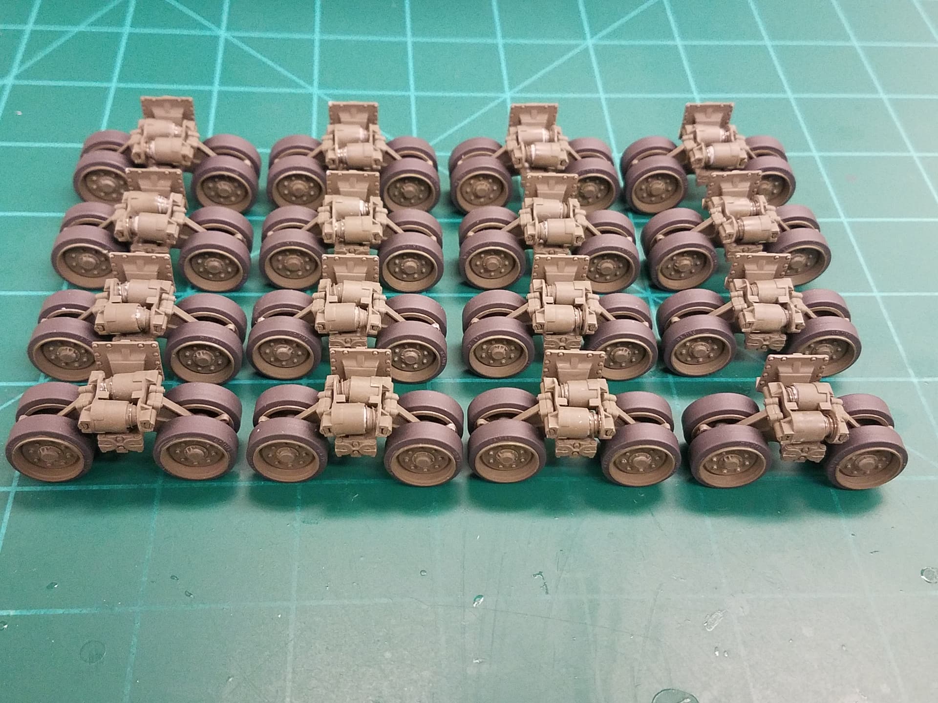
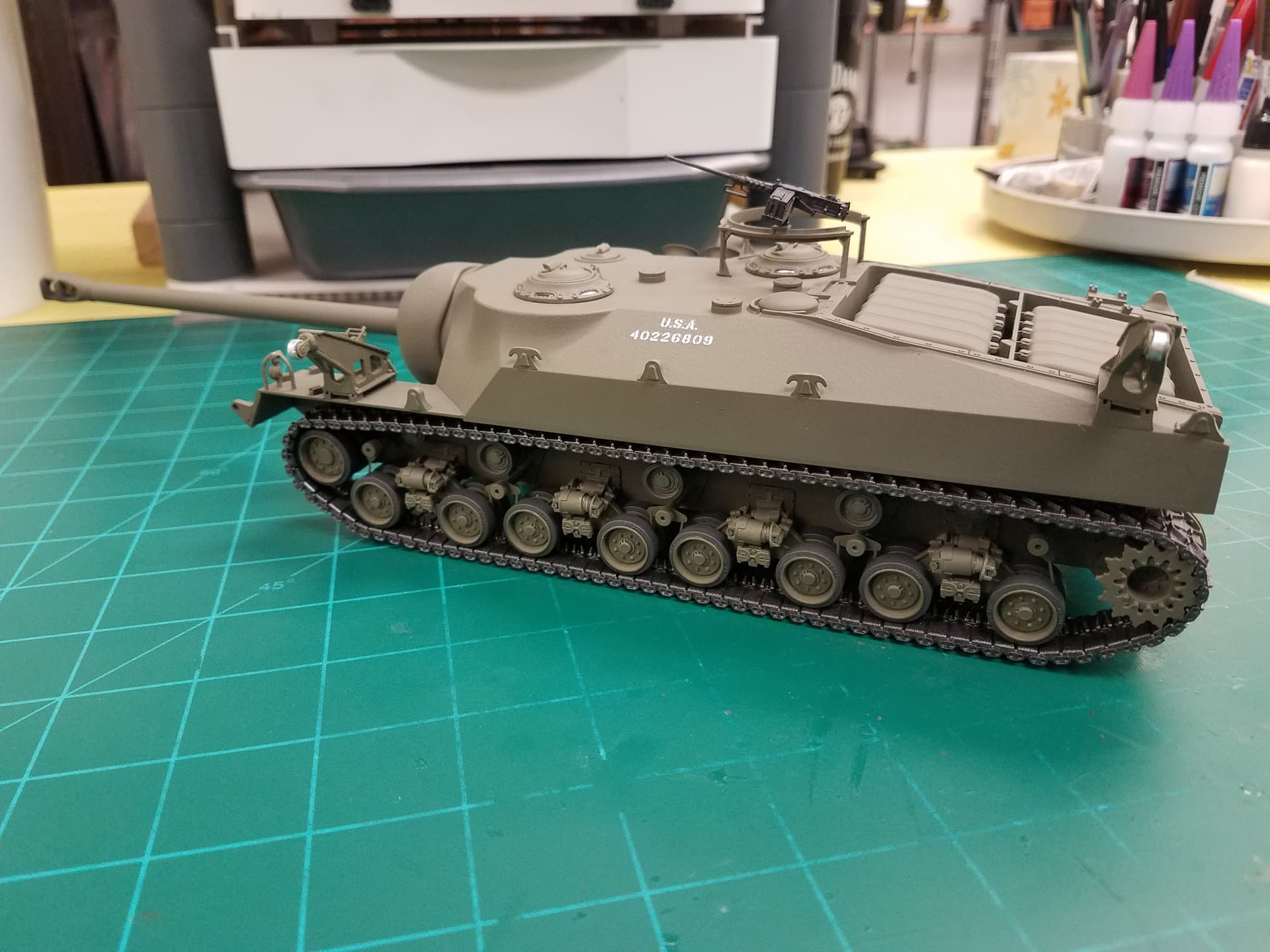
OK, this is my first time posting a build log so I hope I’m doing this right. This is the Dragon “Smart Kit” #6750 issued in 2012. I bought mine then for about $70. It has a ton of pieces, anywhere from 700 to 1700 depending on whether you count the number that are not used, probably close to half of them. The vast majority of parts are for the suspension as you can imagine as there are 4 runs of track.

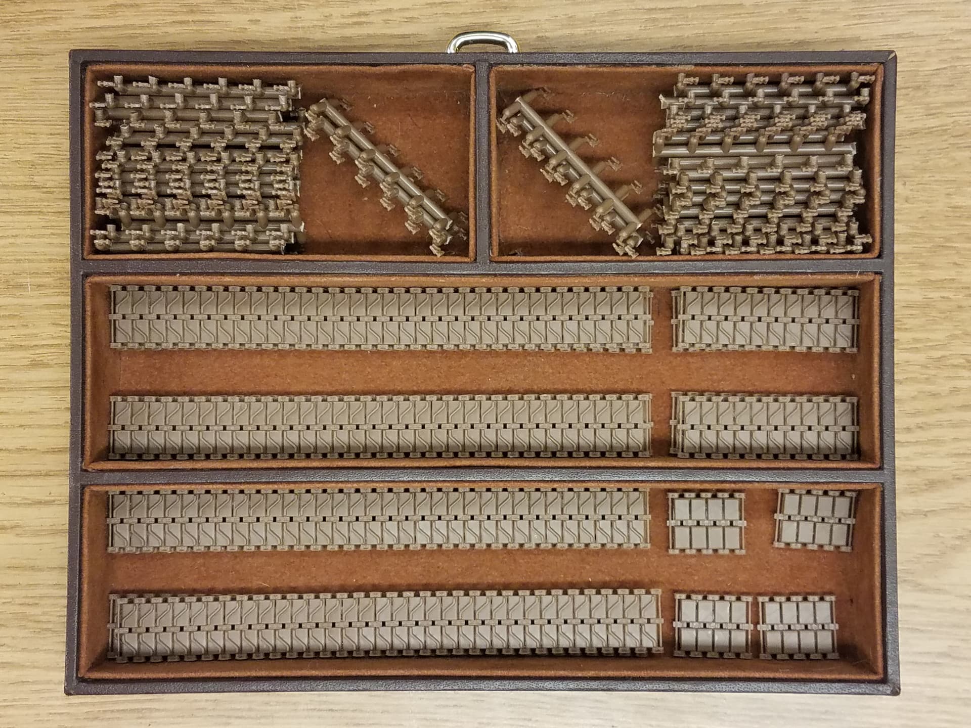
And speaking of tracks, let’s get that issue out of the way up front. The 8 track sections are rubber band type DS and mine were worthless when I opened the shrink wrapped box after almost 10 years. They had started to liquefy in their sealed plastic wrapper and the DS plastic itself was very brittle (note the broken tabs).

The goo had started to leak through the wrapper but, fortunately only got on the parts bags directly under it and didn’t penetrate those. Word to the wise: if you have this kit you’d best open it and see what you have.

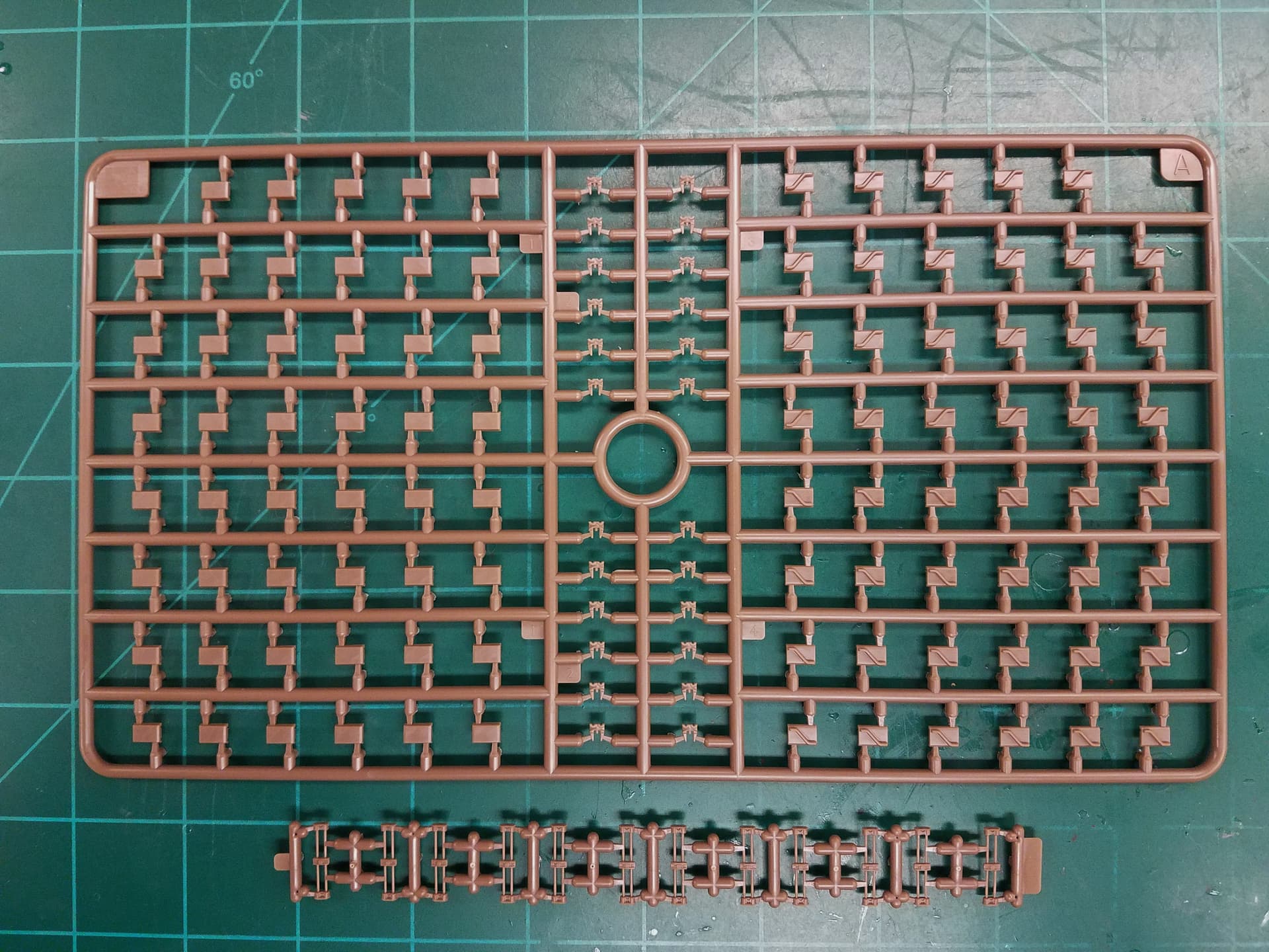
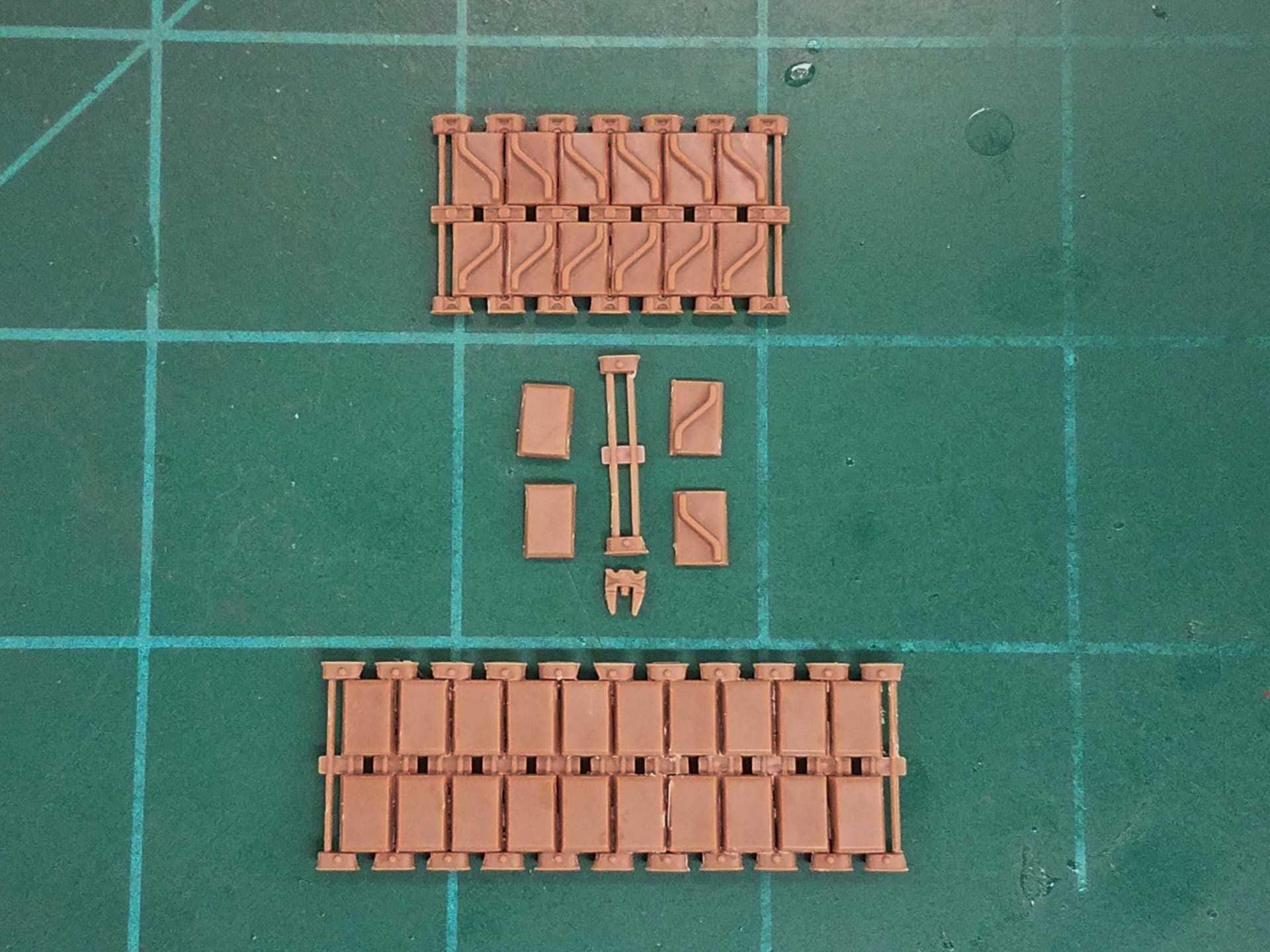
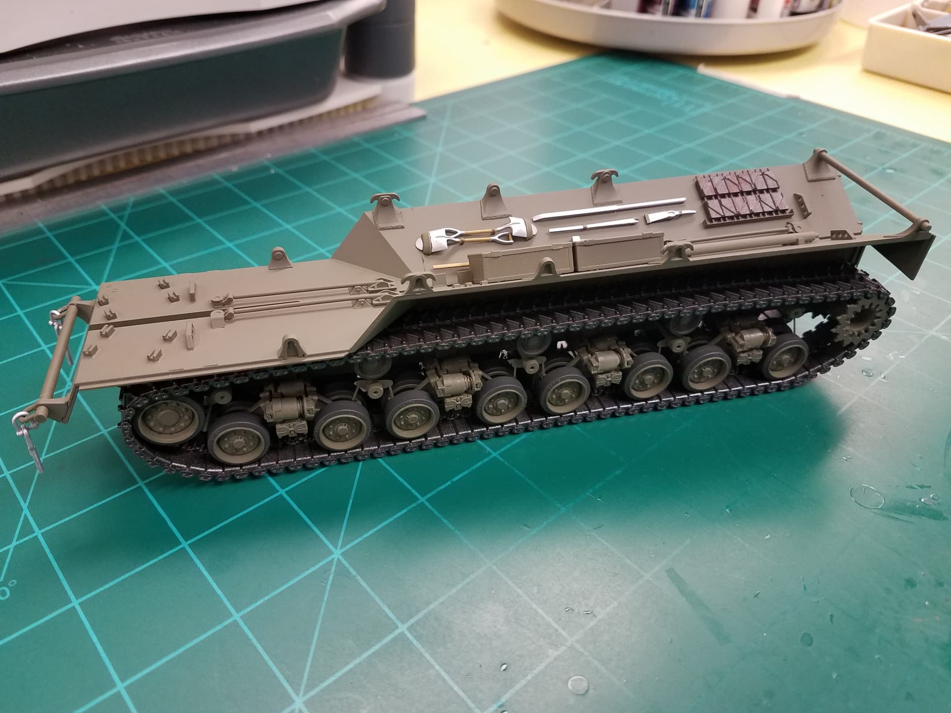
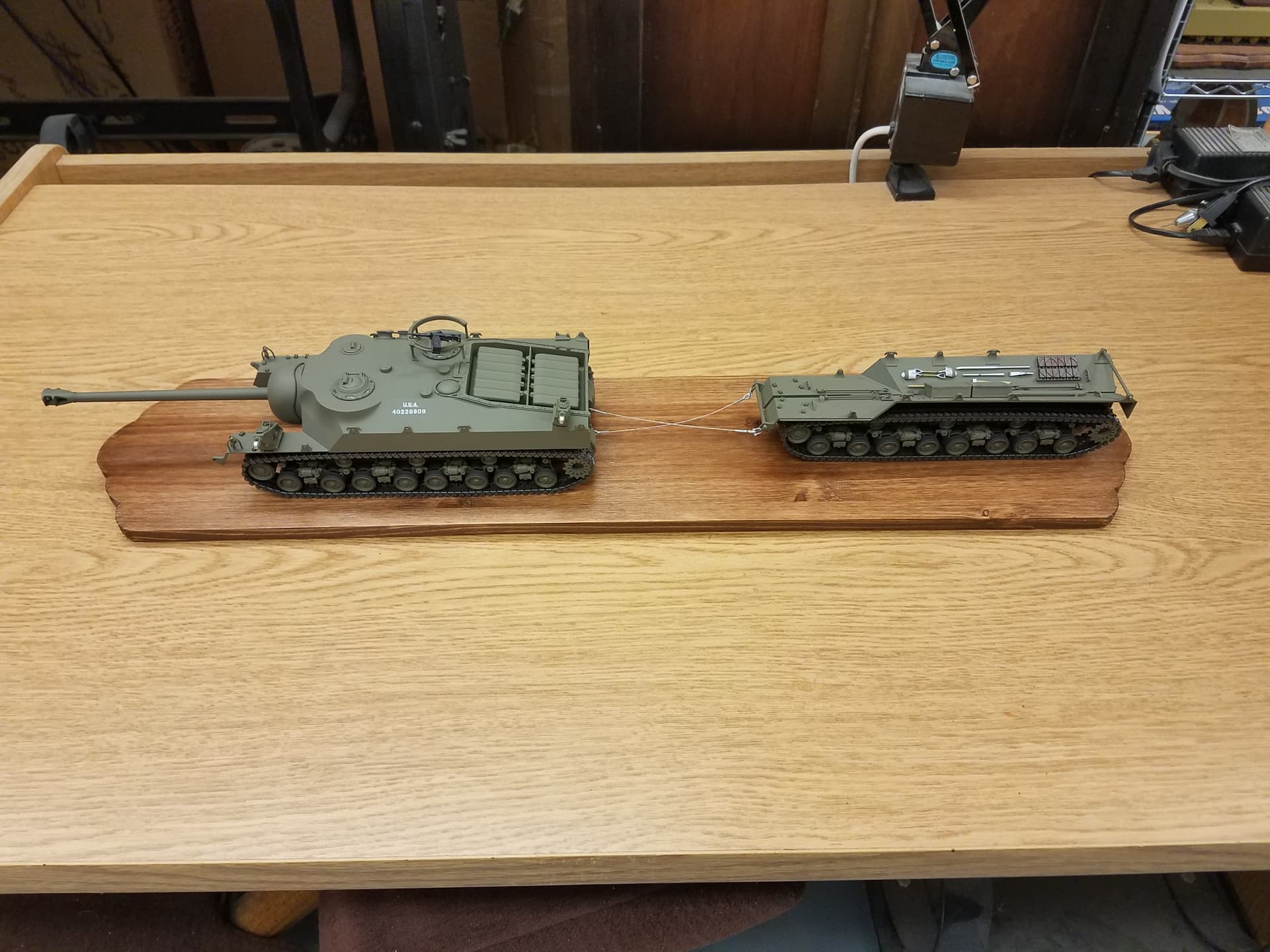
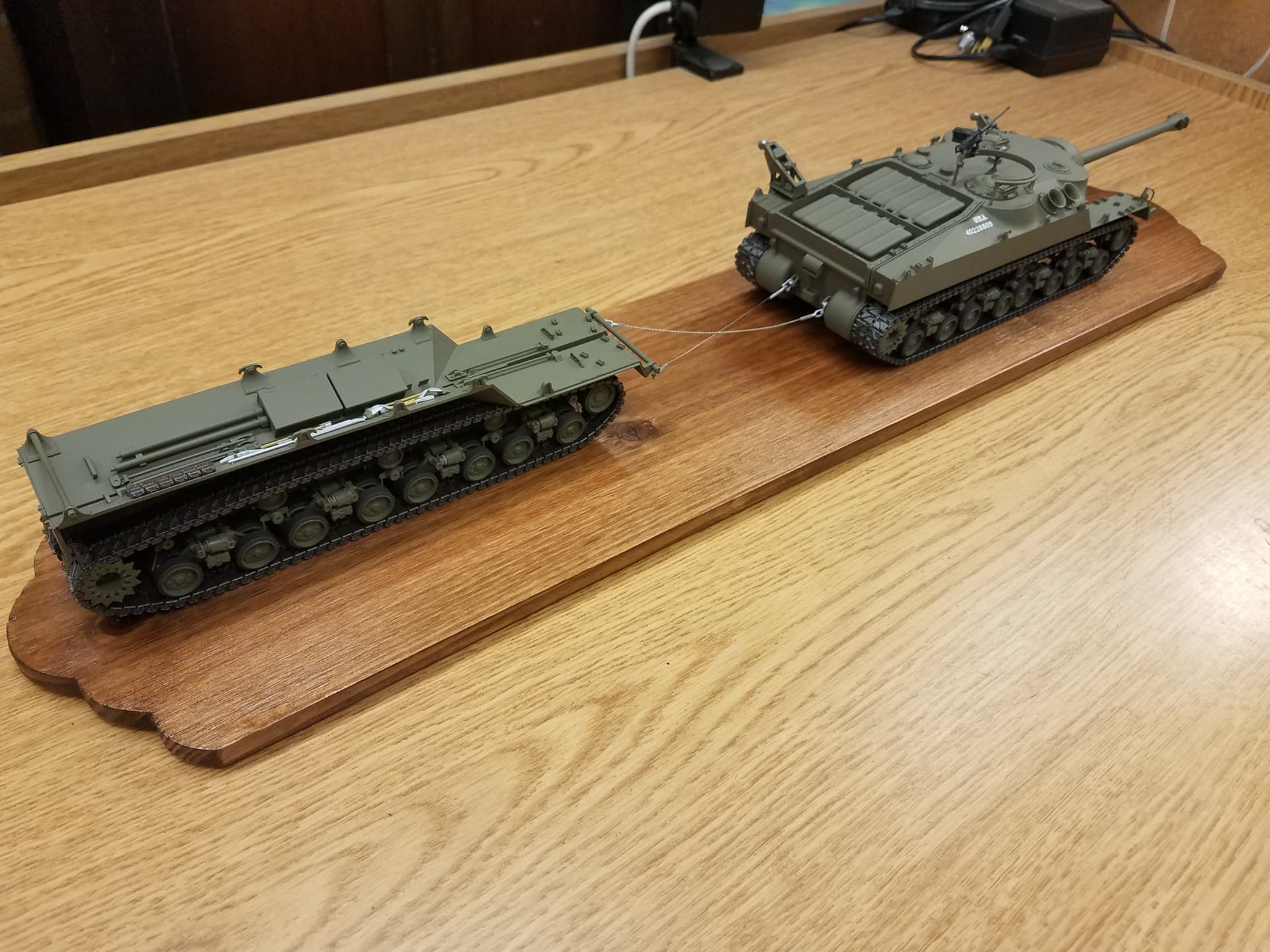
So, after some help from a couple Forum members (thanks again guys) I bought 3 sets of Bronco T80E1 tracks for $70 as replacements. While they claim to be “movable’ I will glue them together as link-length because . . . . . I plan to build the tank in travel mode with the outside tracks and sponsons being towed. Trying to keep them movable will be a headache I don’t need. You’ll need three kits to get enough links for 4 track runs on this beast.

Since there are already a bunch of in-box reviews out there I’ll skip all that and get right to the build. You can check them out to see what all is in there if you are interested. As typical of Dragon, there are mis-numbered parts, vague part orientations, unnecessary holes drilled, and some out-of-sequence construction steps. I made copies of the instructions to mark up as I go along just to keep things straight.

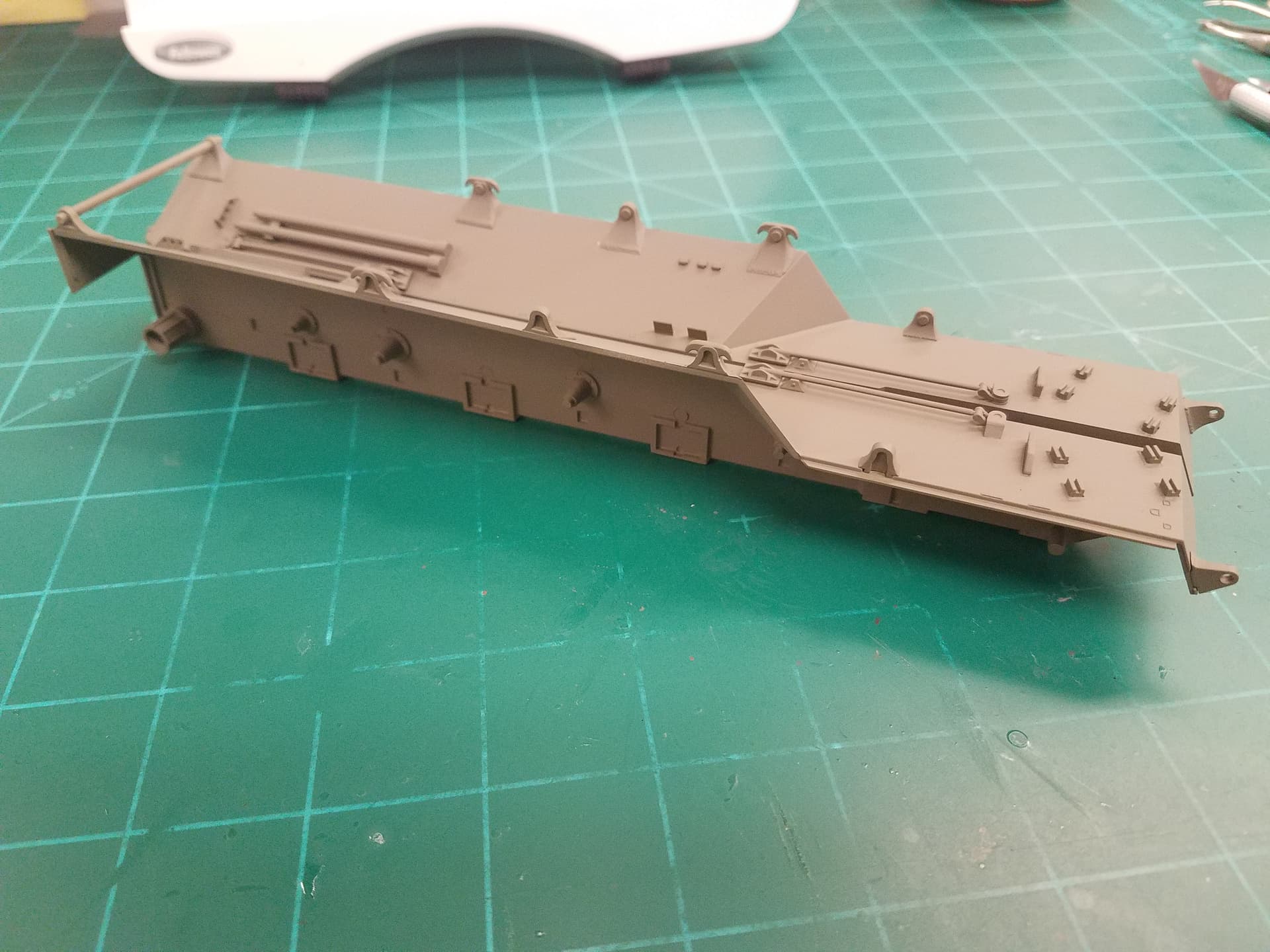
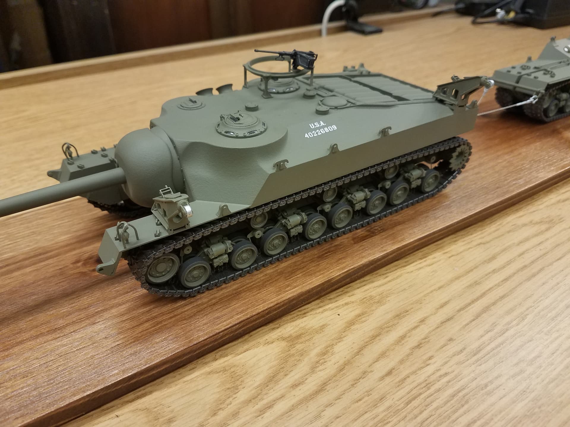
Since the replacement tracks are still a week away I’ll start building the hull and sponsons. The hull fit is fairly good but some of the lifting hooks need some trimming to sit correctly. I am leaving the pioneer tools off till later.

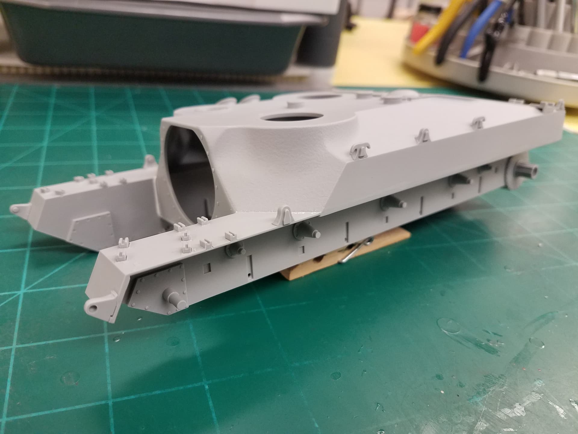
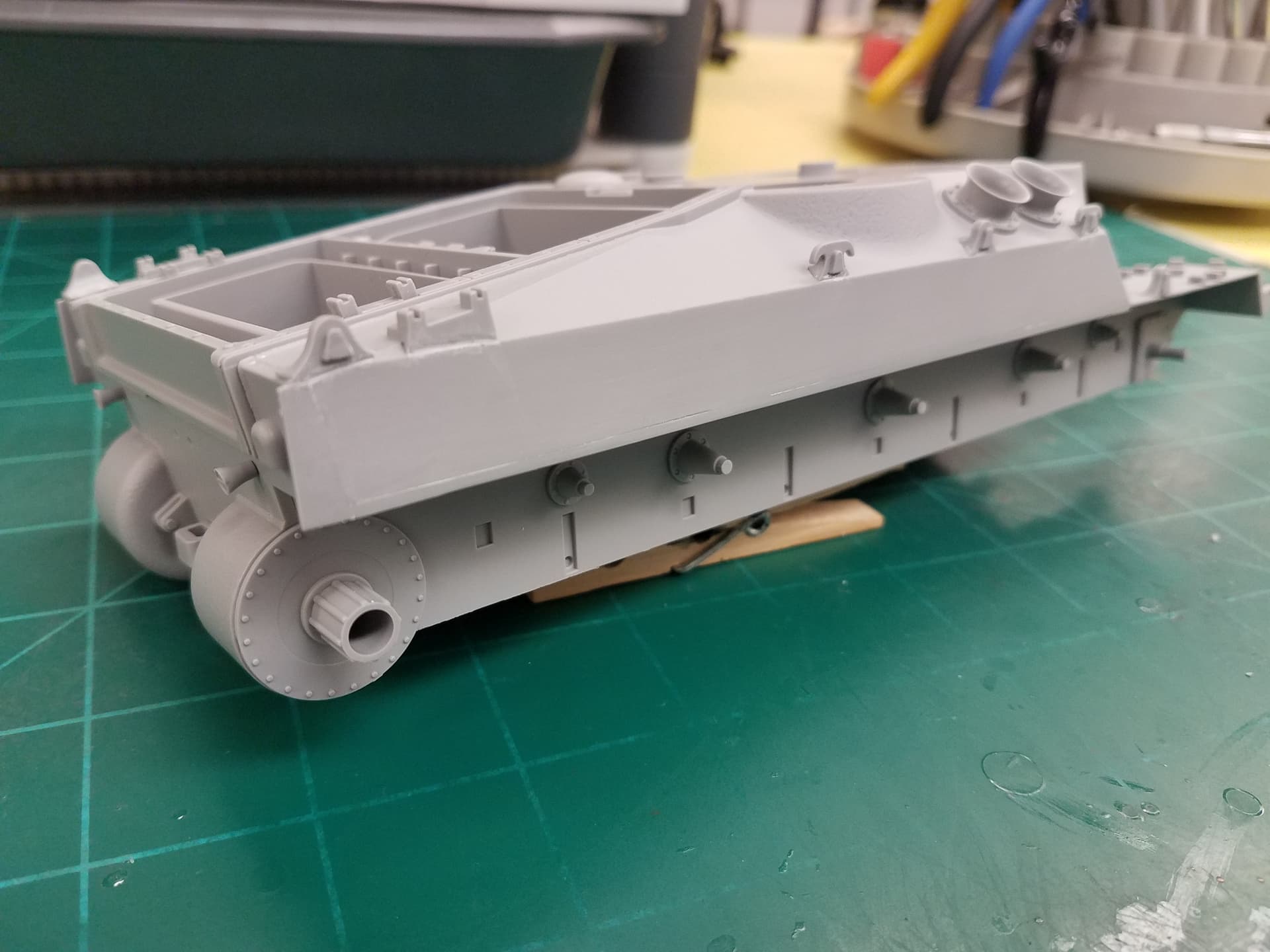
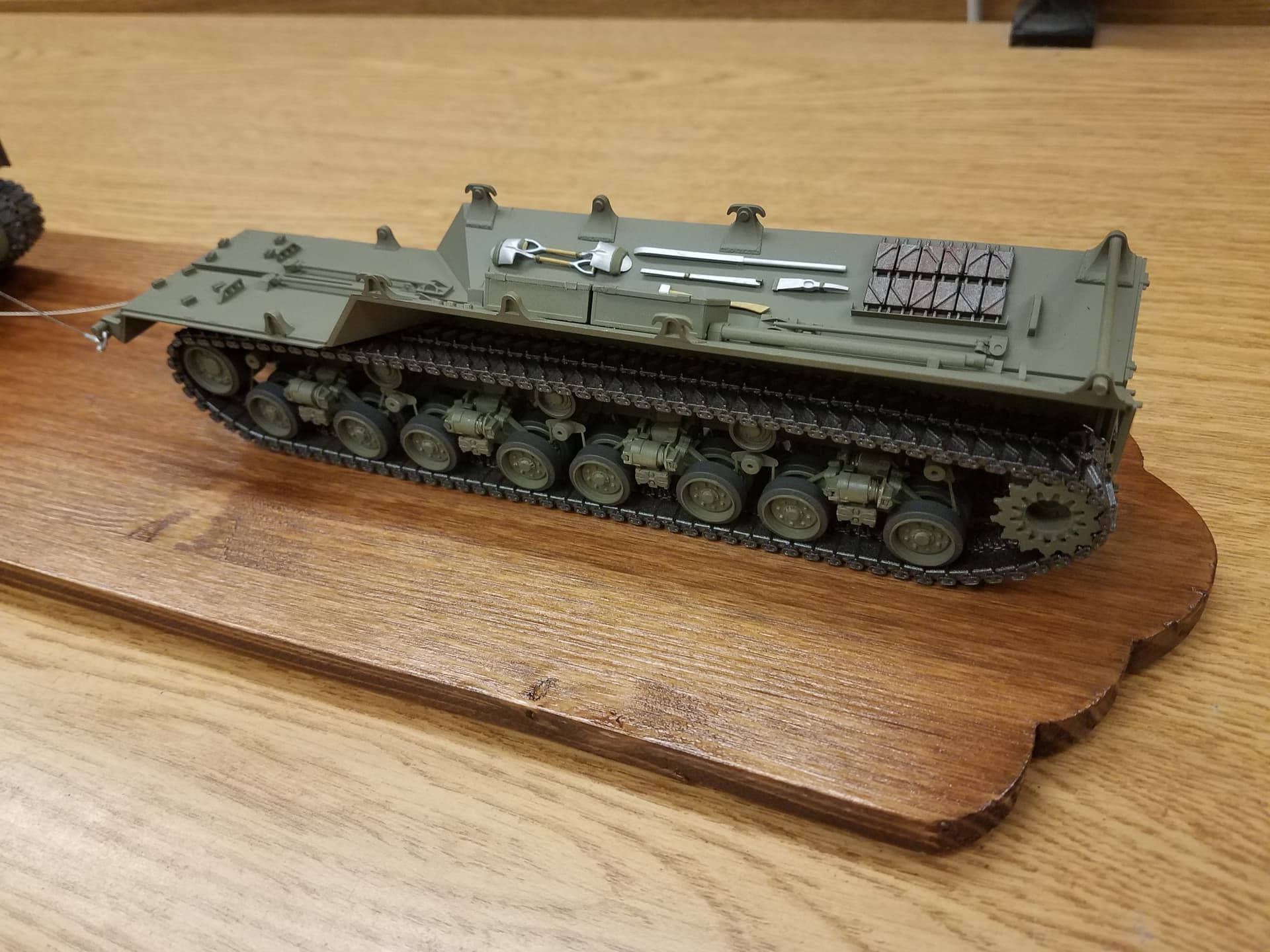
The sponsons are not too difficult but some parts placement is vague.

More to follow.

8 Likes

Looking good so far. A very interesting prototype you don’t see often. I’ll definitely be following along.

tuned in and watching with interest

Here is the next part:

The PE fret is a real challenge. It is more like thick foil than a sheet. You can deform it with bad language, it’s that fragile. Also, the two large boxes do not have score lines at the fold locations so you have to align your bending tool by eye. The box top has fold lines so I used it to hold the lower box sides together rather than try to glue the corners. It worked pretty well but unless you have soft, steady hands, a calm disposition, and a ton of patience, you might be better off making them out of sheet styrene instead. The mud scrapers(?) are a PITA. They are fragile and the round cap piece has one hole just SLIGHTLY bigger than the other. Dry fit each one before you try to glue it or it won’t fit and you’ll end up bending something.

Also, some of them are handed so pay attention to the direction of the square stub on the back of the mounting piece.

Now Holy Fiddly Parts, Batman. I don’t think an octopus has enough hands to hold all this together, glue it, and have anything movable or even aligned. Here are the parts and one bogie dry fitted.

Those are 1” squares on the cutting mat by the way so the finished bogie is about 1” long axle-to-axle by .5” wide. There are 8 right hand and 8 left hand bogies. The difference is in how the spring canisters are oriented. The pictured bogie has the front one on the left. By flipping the canister assembly over (not rotating it), it puts the canister on the right. If you attach the sponsons to the hull you’ll never even see these but I’ll have to make them handed since mine will show.

Now the hard part – how to assemble them. This is just what I came up with, you are probably smarter than me and will find an easier way. Again, this is only if you have them exposed and want them a bit movable.

First glue Q13/14s to Q35s. Next sand the Q35 barrels just a bit and use a broaching tool to very slightly enlarge the thru hole. Check the fit with Q5 and Q12 to see that the parts move smoothly. Now ease the inside edges of the Q4 pieces just a hair top and bottom and also the matching faces of the Q13/14 pieces. Test fit to the assembly for movement. Lastly ease the edges of the Q15 pieces or they will bind inside the Q4 cylinders when the assembly moves. Glue the Q15s to the Q4s. Let the glue set. Slip the springs completely over the Q15s so they rest against the Q4s. Now dry fit Q5/35s/12 and check movement. Slip the Q4s together, compress, and fit between the Q35s. Holding Q5 and Q12 you should be able to move the Q35 parts easily without it coming apart. If it binds, repeat some of the above steps. When satisfied, carefully glue Q12 to Q5. If you want the road wheels to rotate, use a broaching tool again to slightly enlarge the axle hole in the Q35s. Since my tracks are not movable there is no reason to do this. Also, I will hold off installing the wheels until after painting. Now, rinse and repeat 15 more times. Remember, patience is a virtue . . . . . .

Here are the 16 completed bogies and, yes, they all articulate.

Part 3 is up next.

5 Likes

You are a better man than I. I would have left the springs off and glued them all solid. Unless you are going to show it going over rough terrain with an articulated suspension, I don’t see the need for them to be movable.

I had that kit awhile ago,but on second thought i sold it off,have fun,will be watching.

I agree Gino but as I worked on getting the Bronco tracks put together, I realized that the best way was to make them continuous and slip them over the wheels as I’ll show a bit later. I also wanted to see if it could actually be done as the kit intended. Answer : not really without a good bit of work and, as you point out, not really worth it. Anyway, done is done and it did make installing the tracks pretty easy.

The packages of tracks arrived so I started trying different methods to assemble them. It became clear very quickly that Link&Length was going to be the ONLY way to get these puppies together and it will be tedious even at that.

The three kits will give 552 total links and I will only need 408 (102 x 4) so there are plenty of spares available for the inevitable screw ups. These test runs won’t be used in the build but they did give me an idea on how to proceed. I made 24 groups of 10 links each and then assembled those into 8 straight runs of 32. These are the start of the top and bottom track runs. After dry fitting the suspension, I determined the exact length required for each straight run, and made short lengths as needed. Bottom is 37 links, top is 43 links, total of 80. Once the suspension is glued in place, I’ll make the front riser/idler and the rear sprocket/riser links. Finally, I’ll put all the lengths together and add the guide teeth.

Since there are 6 pieces to each link and 408 links needed, 2448 total parts, assembling the tracks is going to take a lot of time. I have some old jewelry box drawers that are just the right size to hold everything until I’m ready to do the assembly.

I’ve started all the wheels and sprockets now. The 64 road wheels and 4 idlers consist of two parts each – the hub and the tire. This makes painting easier for sure but note that the lettering on the tire is only on one side and that must face out when you assemble them. Here are the wheels, painted and assembled.

Now with the bogies painted I can add the road wheels.

As I mention earlier, my road wheels are not meant to turn but because the bogies articulate and only the hubs are glued to each other it will make installing the tracks later a bit easier if they can rotate a little if needed.

6 Likes

The sponsons have also been to the paint shop and are ready for the suspension.

With the upper and lower track runs dry fitted I can measure for the remaining track lengths. After adding the bogies and mud scrapers(?) to the sponsons, its time to build the two sets of tracks. The individual sections are glued together making a continuous length. They will be painted off the model, then slipped over the suspension since the sprocket, idler, and roller wheels have not been glued in place.

It also helps that I have made the bogies movable. Here are the sponsons with the tracks after painting.

I have glued the upper and lower hull pieces together at this point and added some of the detail parts prior to painting. I left off the hatches, machine gun mount, and suspension till later. A note about the main gun: the barrel must be inserted from the rear as it is too big to fit the way the instructions indicate. Dry fit these parts first and you’ll see the problem. Here is the basic hull assembly after painting.

After installing the bogies and other wheels it’s time to do the tracks – again. These will be done the same as on the sponsons: continuous runs, painted off the model, and installed over the suspension with the sprocket, idler, and rollers loose.

With the hardest part over, I can think back on the track building process a bit. It took about 16 manhours to build each of the four track runs using the Bronco ‘movable’ link sets. IMHO these tracks can not be built movable without extreme care in cleaning and assembling the pieces and, even then, the run would be so fragile that the slightest stress could break them. I am also building the RFM M1A2 TUSK II right now and those links are very similar to the Bronco ones. However, they give you a jig to help assembly, the ‘connectors’ are stronger and require less cleanup, and once assembled are quite strong and movable. Just my $.02 worth. Your mileage may vary.

Final assembly of the sponsons includes pioneer tools, spare tracks, and a few other miscellaneous parts. Here are the completed sponsons.

The finished model is next

4 Likes

Final assembly of the hull includes the machine gun mount, hatch covers, and a few other miscellaneous parts. Here is the completed hull.

The crossed tow cables are attached to the hull and sponsons with clevis and cable eyes with a spreader bar at the sponsons. The only decals are small ones on the upper center of the hull on each side. A quick shot of Dullcote and we can call this one done. It will later be permanently mounted on this 26” wood base, I just placed it there temporarily for now. I think it is an unusual presentation of an unusual tank.

Only two prototypes were ever built and they never saw action. The last remaining one has been rescued, refurbished, and is in running order now.

7 Likes

Rick, that is an absolute monster! I think you’ve done a fine job, especially on those tracks and running gear (which was giving me sweats just looking at).

Was the tank actually meant to tow its own bits like that or is it just a creative way to display it?

Very nice. It came out looking great.

Yes, Canmedic, it was designed to do that. The small cranes on the side of the tank hull can be relocated to either side to load/unload the sponsons from the main body. You can see the empty attachment points for the cranes on the right side of the hull.

2 Likes

Rick:

Great work — and what a mouthful. “You’re a braver man than I . . .” I have a couple comments on your build, and one regarding the kit itself.

And yes, for other modelers, these vehicles were intended to tow their own removed outer track sections, just as Rick has this depicted.

My first comment is about the kit. We all know that Dragon took a short-cut and used existing HVSS (28” I think) tracks for this kit, when the tracks were supposed to be a narrower version (23” if I remember correctly). I can’t recall the track nomenclature at the moment. Anyway — the shortcut resulted in the model being too wide, and the side angles being incorrect.

In looking at your completed outer track sections, it looks to me that Dragon put the idler mounts too far to the rear. I understand that the positioning of the idlers can be varied to adjust track tension, maybe I’m wrong, but to me the idler mount really appears to be too far to the rear. I think that if you were building this kit with the outer track sections in place, you wouldn’t normally see this error. But with the way you have opted to do this build, that issue is much more visible. I’m guessing that you are beyond making changes for this (possible) issue at this point.

There are a couple bits missing from your depiction of the T28. I think that Dragon didn’t really intend for the model to be displayed with the outer track sections removed, at least not without extra work (beyond what you have done here). At least one of the outer track sections actually has a stowage box built in, so that part of that in-cut angle actually appears to come straight down along its edge. I’m terribly sorry, my description is quite poor. The very thick armor of the angled front section is also quite obvious with the outer track section removed, and Dragon has not really depicted this very well.

Additionally, the sprockets on the main vehicle have a fitting on the outside that allow them to be connected to the outer track section sprockets, so that all 4 tracks are powered when the vehicle is assembled. This fitting, or adapter, is rather complex, with lots of bolt holes & raised lips, if I remember correctly.

Finally, the capstans that are normally stowed on the upper right hull? These are attached to the outer track section sprockets when they are being towed. A rope is connected to the rear of the outer track section, and wrapped around the capstan, and then spooled out behind the train. The intent was that two crewman — one for each side — would walk behind the entire train, holding the ropes, and pull on the ropes to act as a brake if the train was going down a slope, to prevent the outer track sections running into the towing vehicle.

The obvious thing to be added here is that your finished model really ought to have the two crewmen holding the rope out behind the train.

All of these features are shown in Hunnicutt’s “Firepower” . . . I have my own (rather poor-quality) images of all these features (except the attachment of the capstans and their use) that I attempted to attach here, but I got an exclamation point in front of the file name, and translated that as FAIL, so I can’t help with pictures. I’m thinking you can probably find pictures of all these features online.

Anyway, great work. I am really impressed. I would like to say that I will build my T28 one of these days, but other projects always beckon. :frowning:

Mark

No, the exclamation mark is correct, part of the coding. Once you complete your post, they will load properly.

Would love to see your pics.

:hushed:

OK, let me see if I can make this work . . .

Trying again

1 Like

Number Two

Sprocket attachments to connect the two sprockets:

And the other side:

And lastly, a very poor-quality shot of the outer track sections. You can make out the thickness of the armor here, on the sloped part at the front. This also shows the stowage box. I cannot tell you if there was a similar box on the other side; I would think so. When this vehicles was refurbished, they found the users manual in the stowage box.