Hi all
I recently started this model from a company new to me. The first impression is far from excellent. It reminds me of late Panda hobby quality.
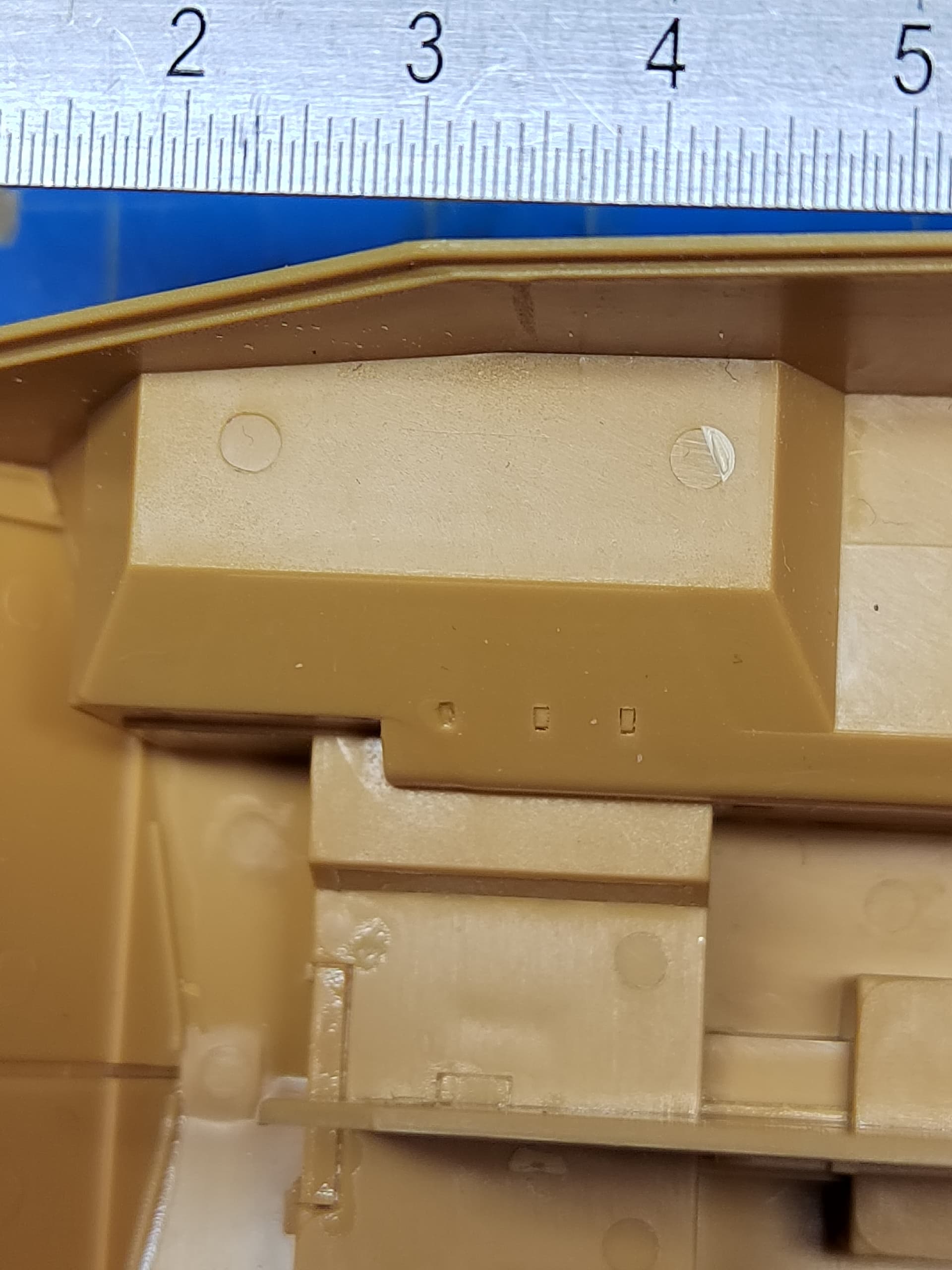
You have to thoroughly clean all the parts so they can adjust. Most of the contact surfaces present ejection pin marks. Several parts have no mark to be positioned. The instructions booklet is sometimes a guess game and presents some part number mistakes.
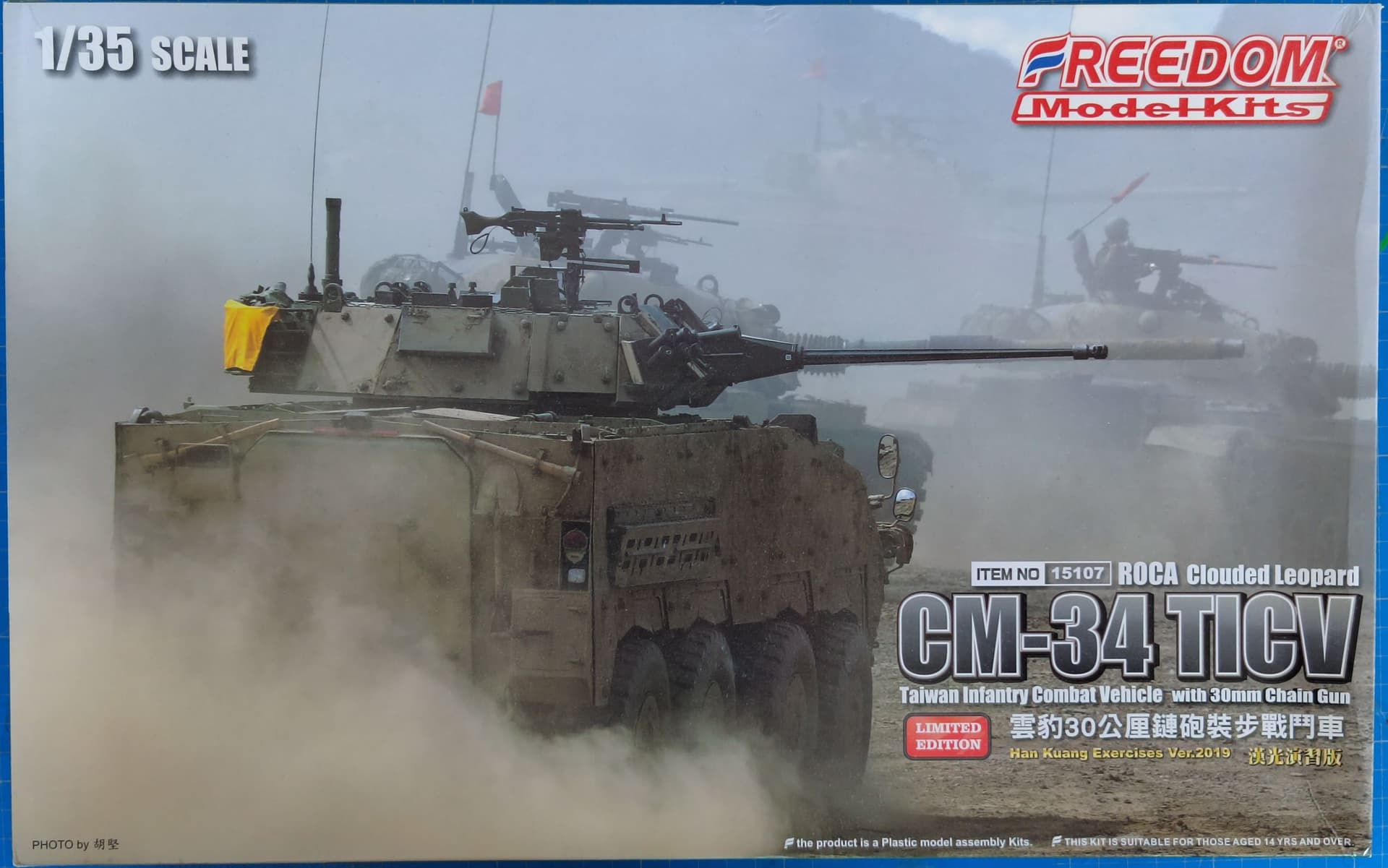
The first step is a series of sub-assemblies build numbered 1-A et 1-N. All the sub-assemblies for the suspension should be marked as you utilize them at steps 4 and following.
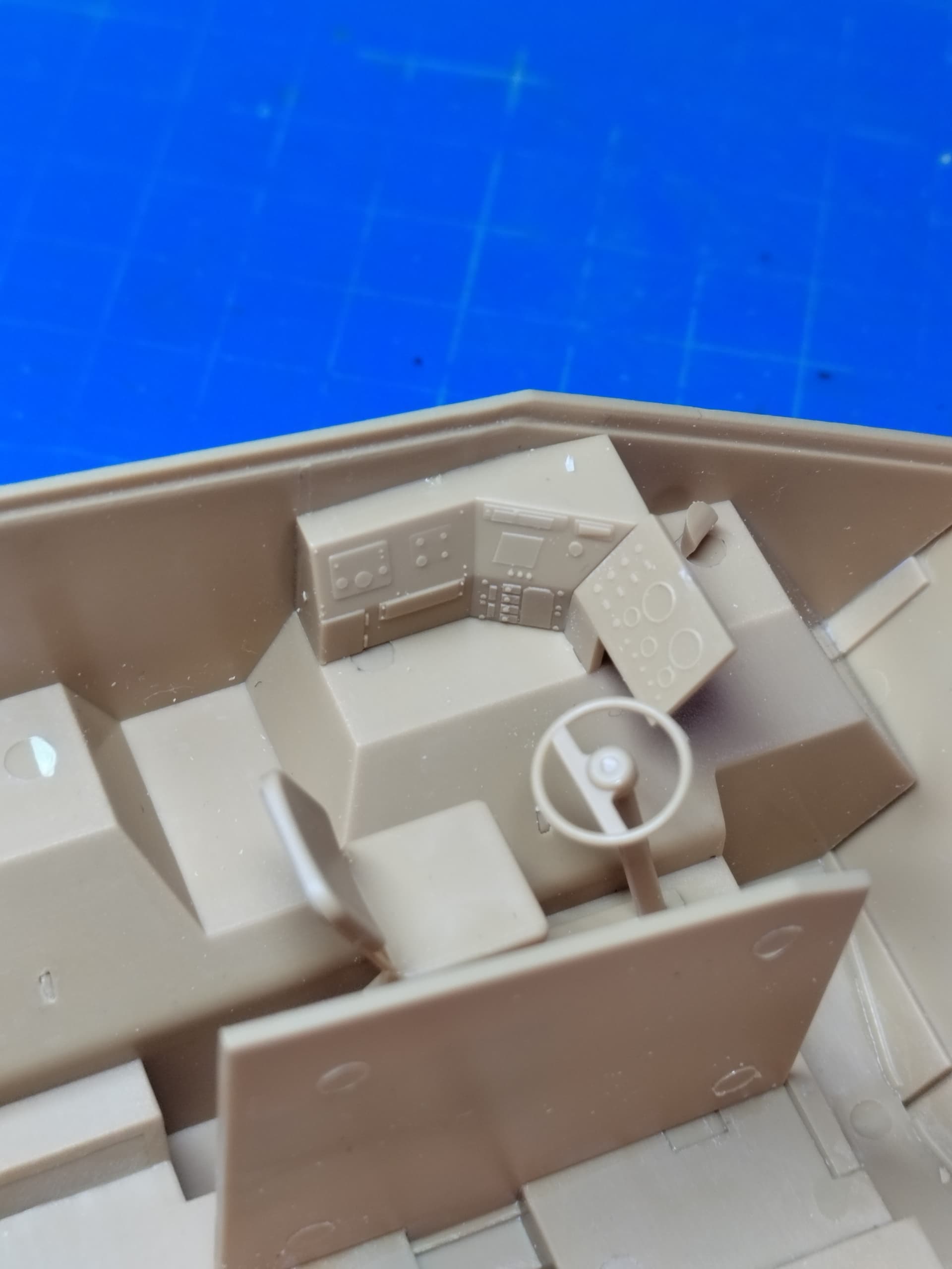
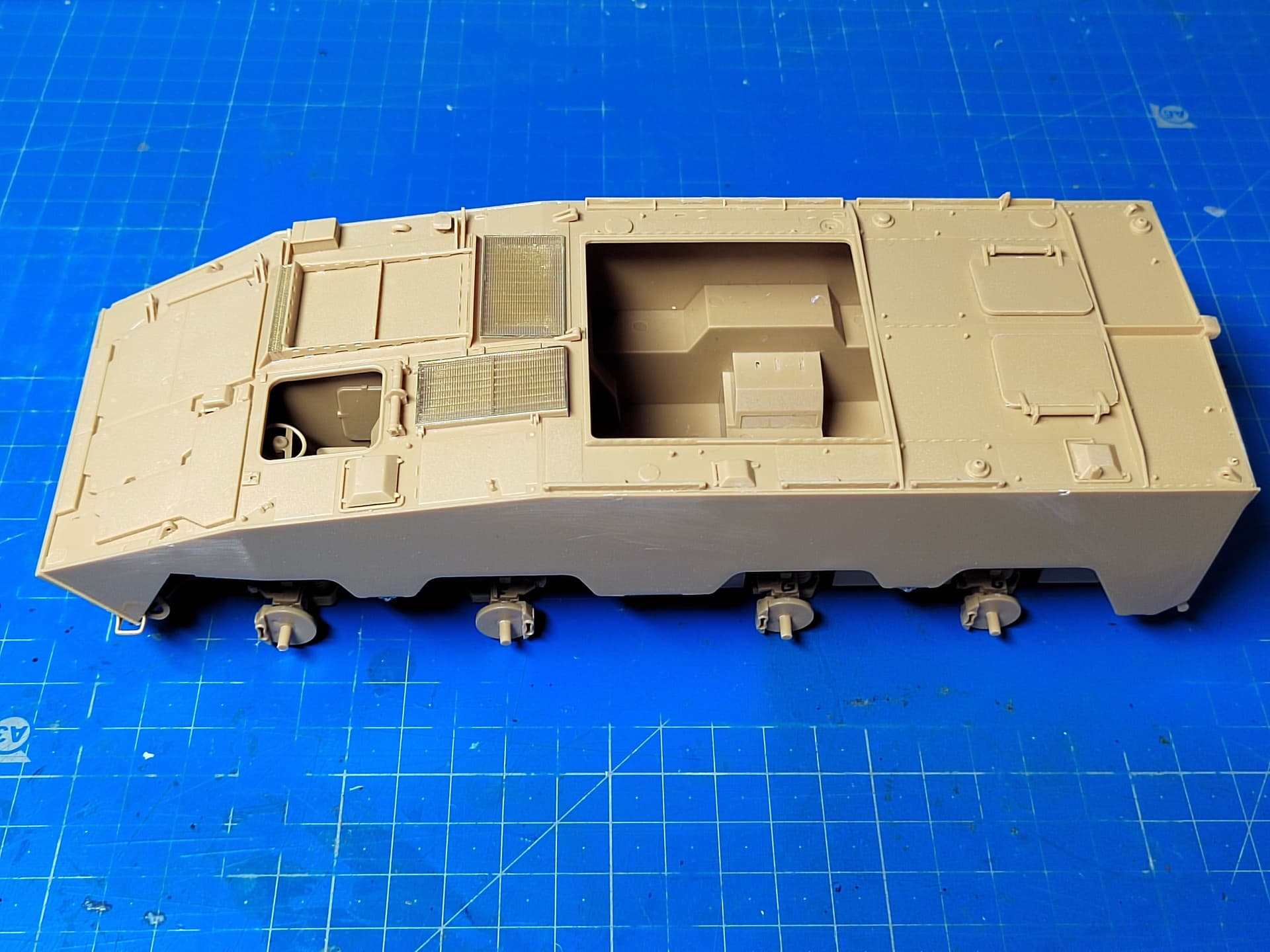
The hull roof is made of 3 plates on which FMK ask you to add all the details before gluing them onto the hull. This method is quite surprising and I generally avoid to use it.
The first really important fit issue is due to the hull right side which is warped preventing the rear wall to be fitted. This is a true issue as you have to glue the rear wall before gluing the roof elements. I think I’ll add some kind of spacer the keep the side wall parallel and help fit the rear wall.
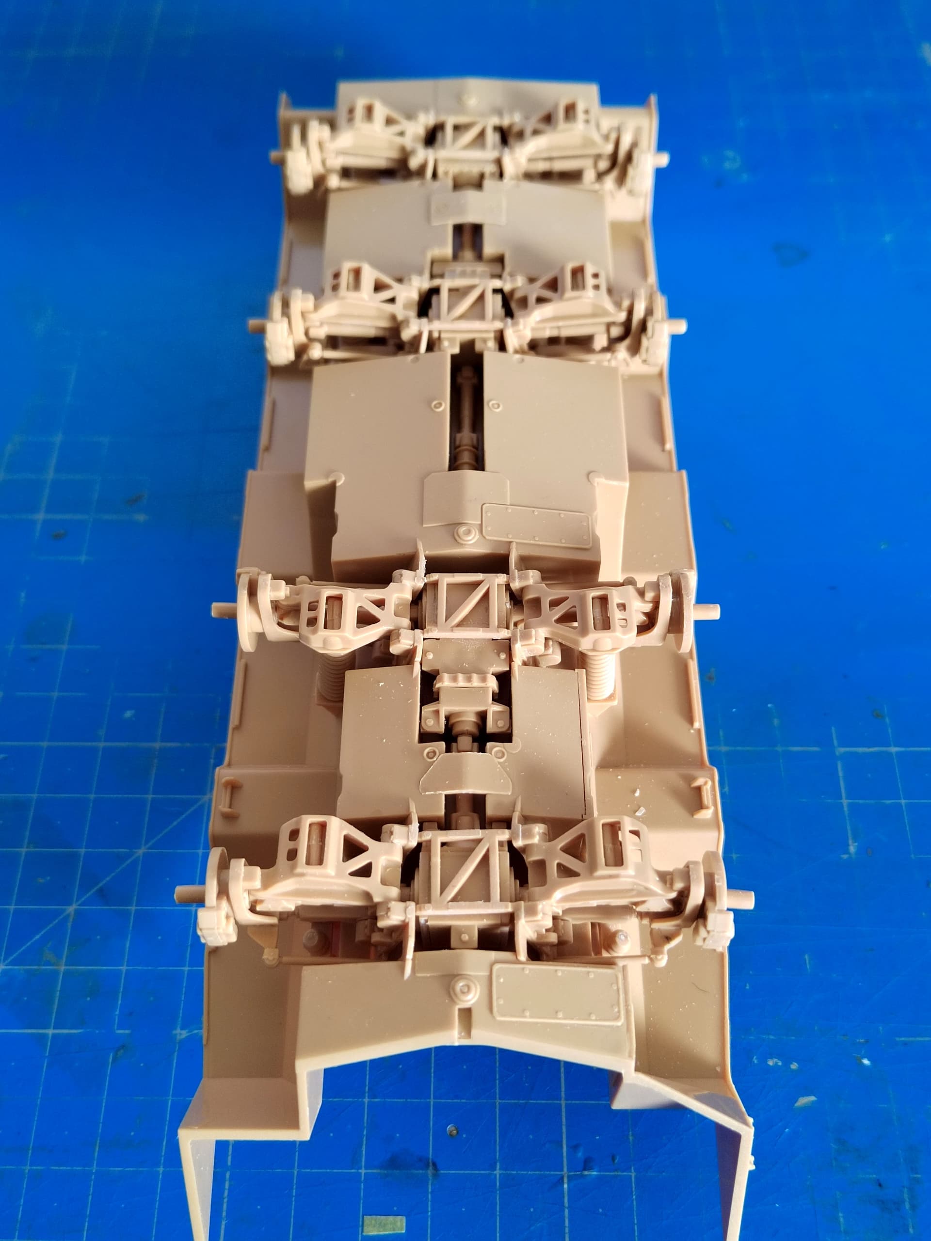
FMK do not provide a full interior but only a simplified driver station. The rear access ramp can be lowered opening into a large void.
Interesting build Olivier- I did the AFV Club version a few years ago and it was a brilliant kit. I don’t remember any interior parts in their kit though.
@Karl187 I’m sure AFV Club team have a better quality control than FMK.
@Johnnych01 I guess this will not be the last issue!
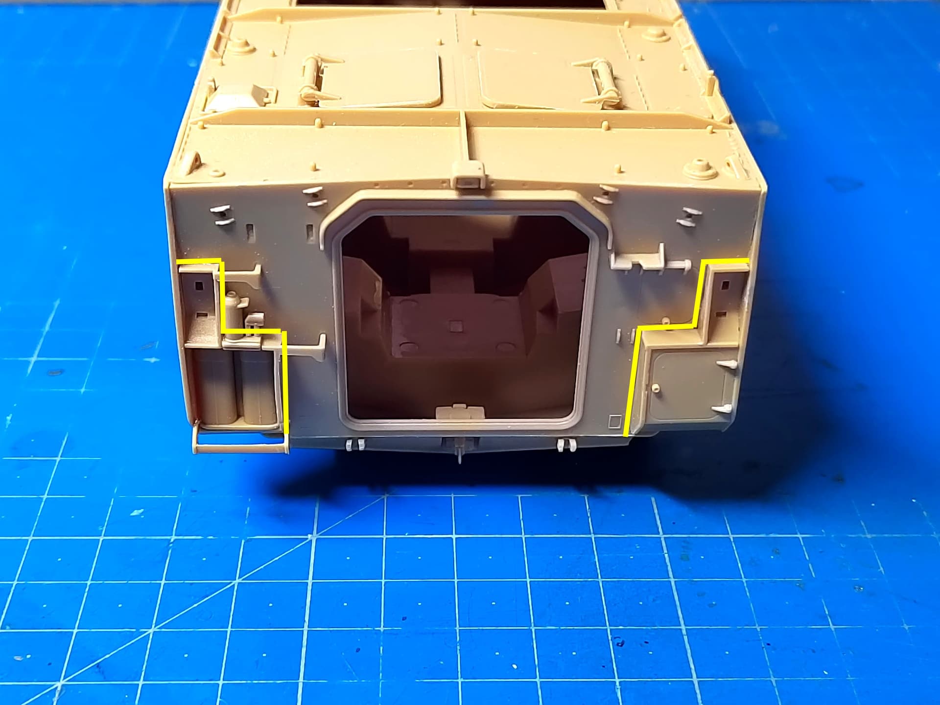
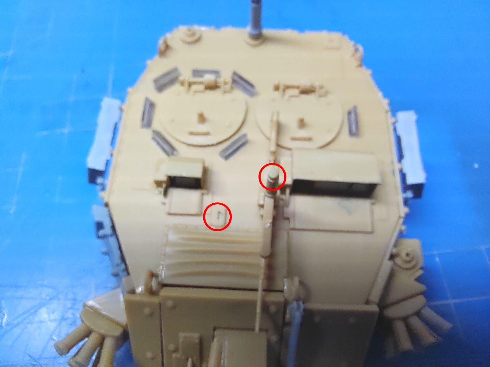
I managed to glue the rear wall by temporarily attaching the rearmost part of the roof. Tamiya extra thin glue did its job once again with its low curing time.
Then I had to insert the rack and the bin in the bottom angles (highlighted in yellow) . I did say insert and not glue to the rear wall which would have been easier. So again I sanded the sides of the both parts so they can fit in the spaces. Not a big issue but it’s time consuming.
I had this issue with the etch for my Warrior. After struggling with the first couple of pieces I started keying the surface with a few swipes of a sanding stick, after that had no issues.
Thank you Johnny.
I have painted and glued the headlights and their protection and started the turret assembly.
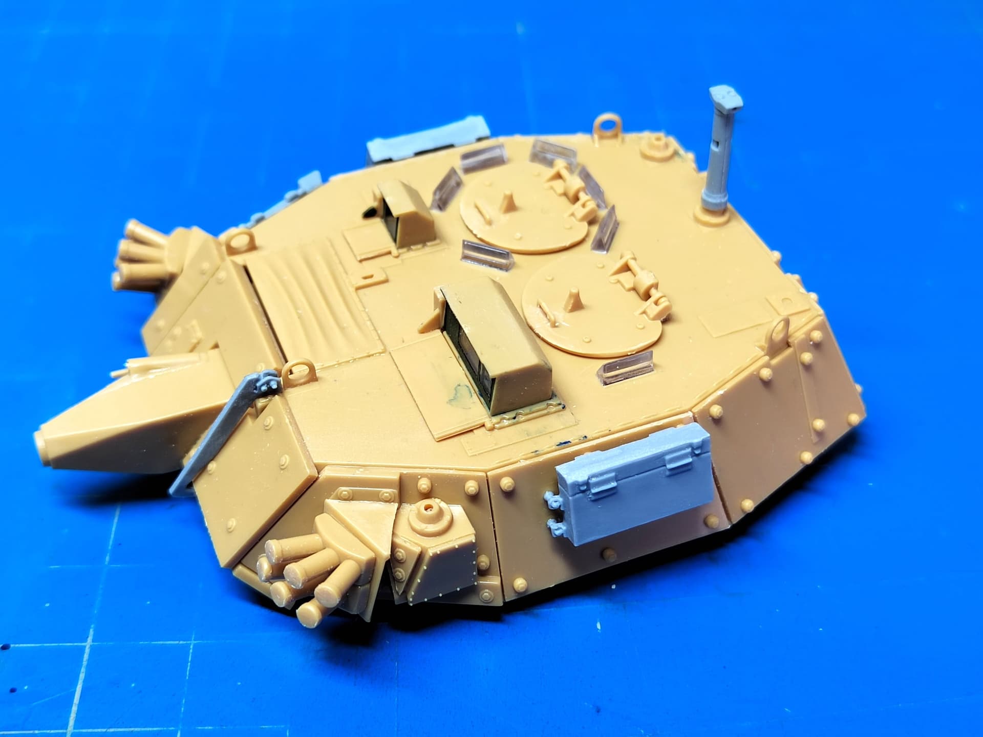
The turret shell features few marks to position the parts. This is particularly true for the add-on armor panels. In fact there are indents in the turret and very very thin “tabs” at the rear of the panels. The result is the parts cannot be put in place with the “help” these marks.
The both sights housings have a nice sink hole! I fixed this with some sprue bits diluted in Tamiya extra thin cement.
The special edition model I have includes resin parts. They are nicely cast. The turret sides have no marks at all to glue the smoke grenades boxes. So I eyeballed their position.
The gun barrel base is totally flat and so is the mantlet. Again no marks are designed to align the barrel in the right position. This is the same issue with the smoke grenades dischargers. And concerning the MAG 58, its base is round while the base on the turret has a half-moon shaped hole.
I doubt there is any quality control team at FMK.
Today I tackled the turret basket.
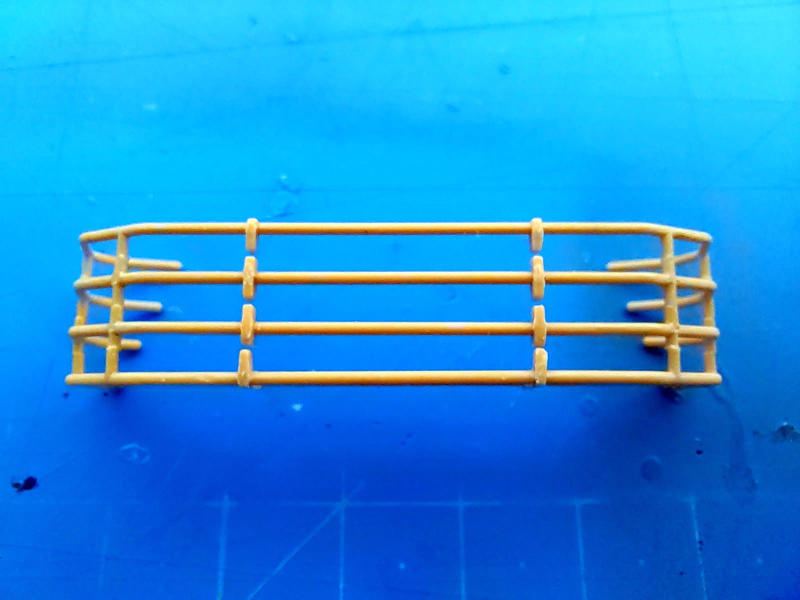
FMK ask you to shorten some supports for the horizontal bars. No measures are given in the instructions. You only have a photo of the basket assembled. If you shorten the supports according to the instructions the mesh parts will appear above the horizontal bar and probably the ends of the bars will make contact with the large bolts on the add-on armor panels. So I decided not to shorten the supports and instead to assemble the basket as it is. Here is the result.
Then I cut all the central supports i.e. the ones which are too short. I replaced them by lenghts of styrene and added the mesh parts. They are a perfect fit, good point for FMK. However to bend the side parts FMK have etched marks so tiny that you nearly can’t see them. You could think they are flaws in the parts. So you need to be extremely careful here.
In the end, here is how the basket looks. Unfortunately I glued one mesh part slightly too high.
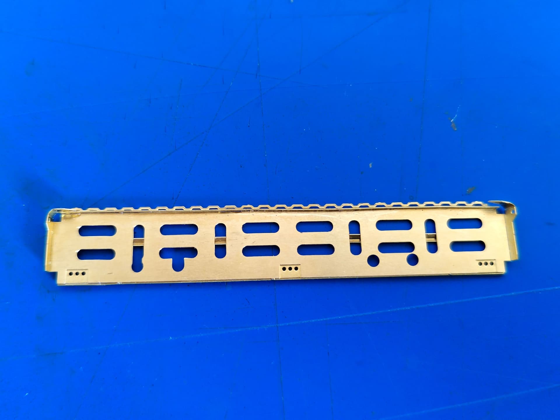
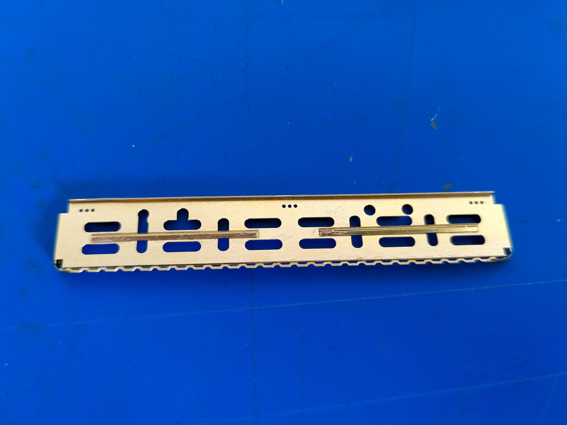
Yesterday I started to build the hull ride racks. They are provided as multiple PE parts by FMK. I managed to shape all the parts for the left side only. And as I will represent the rack folded I did not make the “workable” hinges which saved me a lot of time.
The rack consists of two parts directly fixed to the hull and one moveable platform linked to the hull parts by 3 hinges and 2 scissors on the sides.
FMK allow you to represent the rack folded or lowered. The hinges and the scissors should be assembled accordingly. The various axis can be made with PE parts, metal wire or styrene rod which I chose to do.
Here are some pictures of the various elements.
Lower hull part
I will post a picture of the set dry test fitted later.
Still the second set to build.
Apparently the racks were added after the vehicles were painted and did not get the camo. So I will do the same.