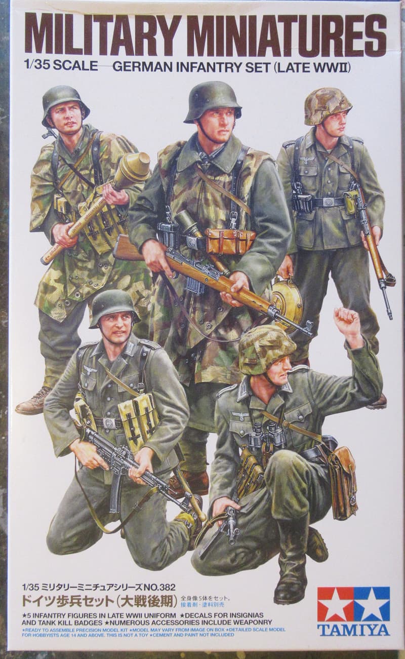
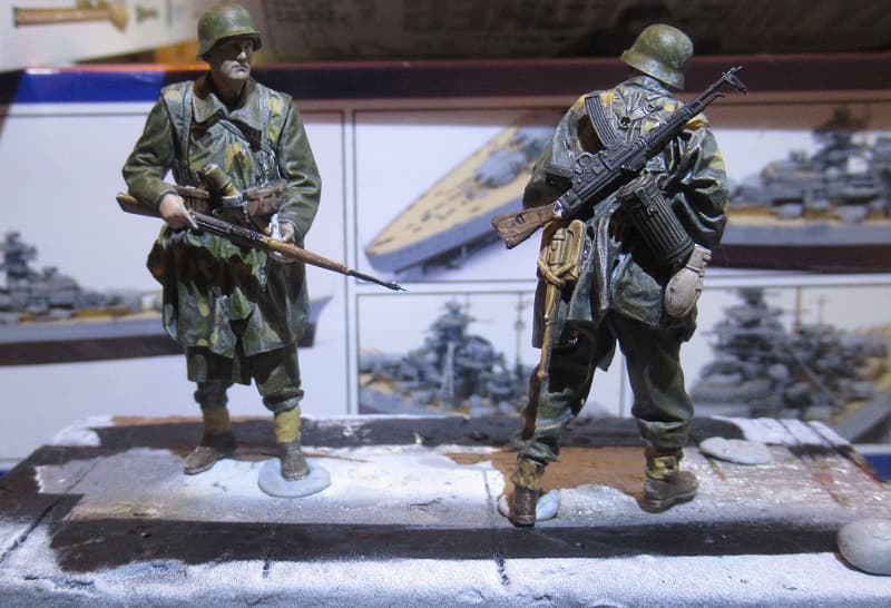
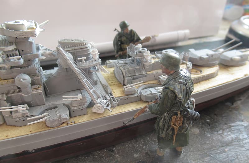
Building Dioramas for me is all about the interaction and unspoken communication between the figures depicted in the story, and that’s what a diaorama is, it’s a story about a moment in time.
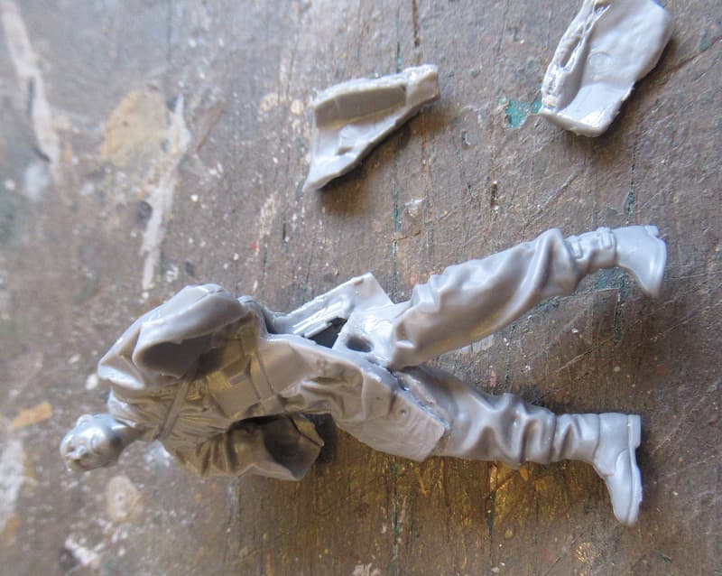
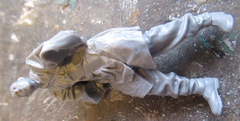
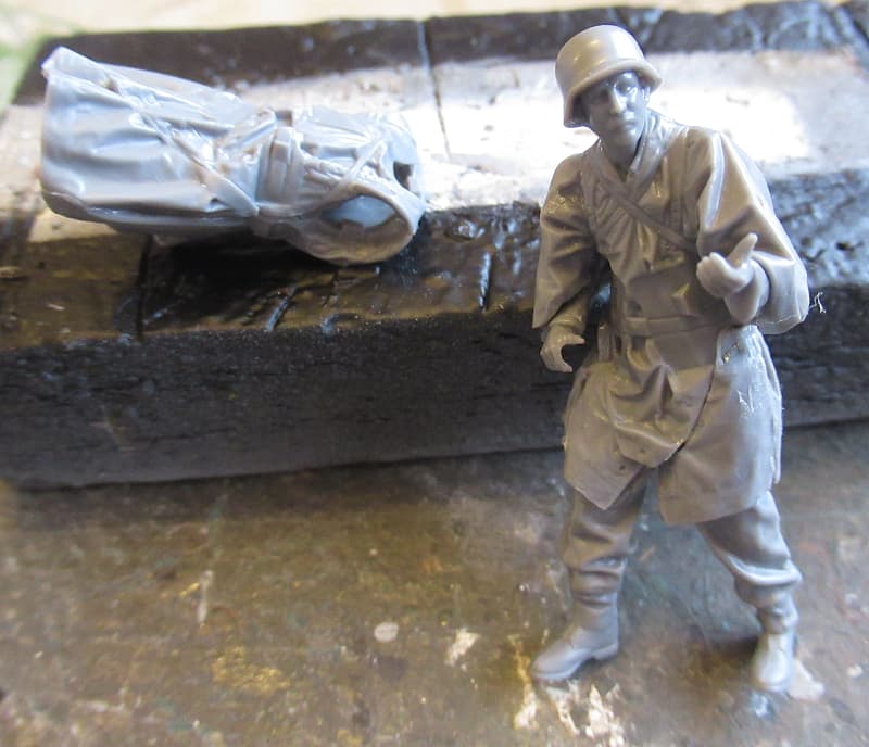
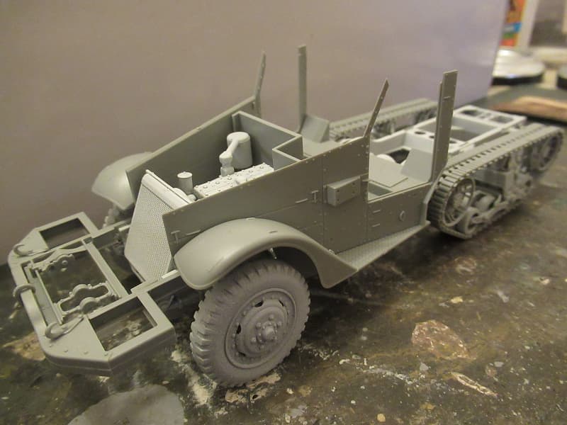
it will be abandoned with the engine covers raised and the drivers door ajar as if the former owners left in a hurry after it woundn’t start, there may be minor small arm damage to it, but I’ll tell you more about the Halftrack and groundwork later on, for now it’s striving to improve my weakest area, figures. so here we go with the first one out of the box.
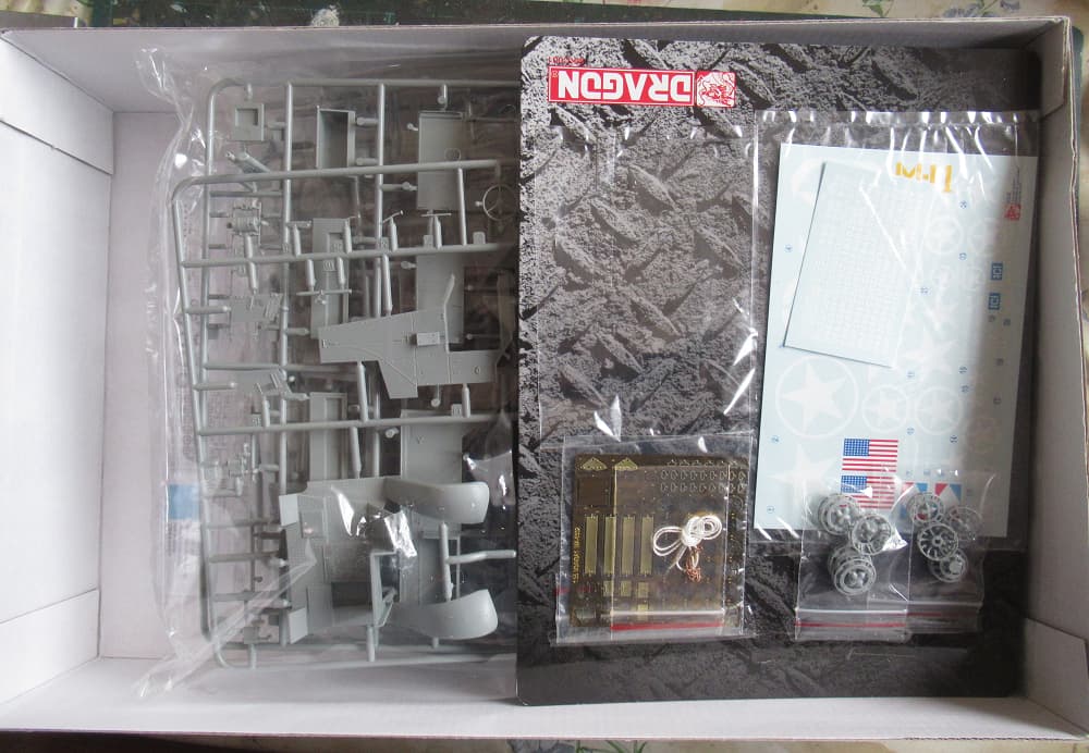
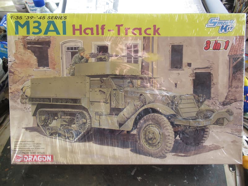
The Dragon M3 provides enough spares to make an M3, M3A1, and if you’re a bit daft, the M3A2, that last didn’t make it into production. So it’s a lame Duck.
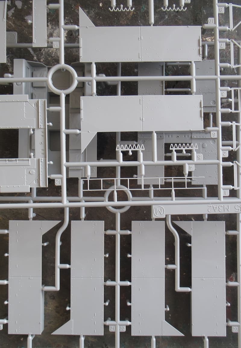
later I’m planning a different build of the Tamiya M3A2 as a fully crewed up M3, So I’ll be using the hull sides and rear plate from here for that. I think this is probably the A2 version.
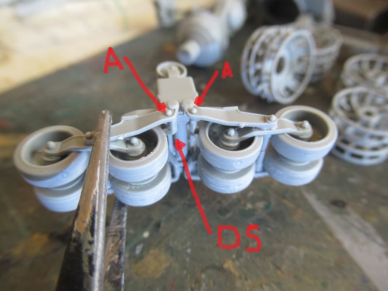
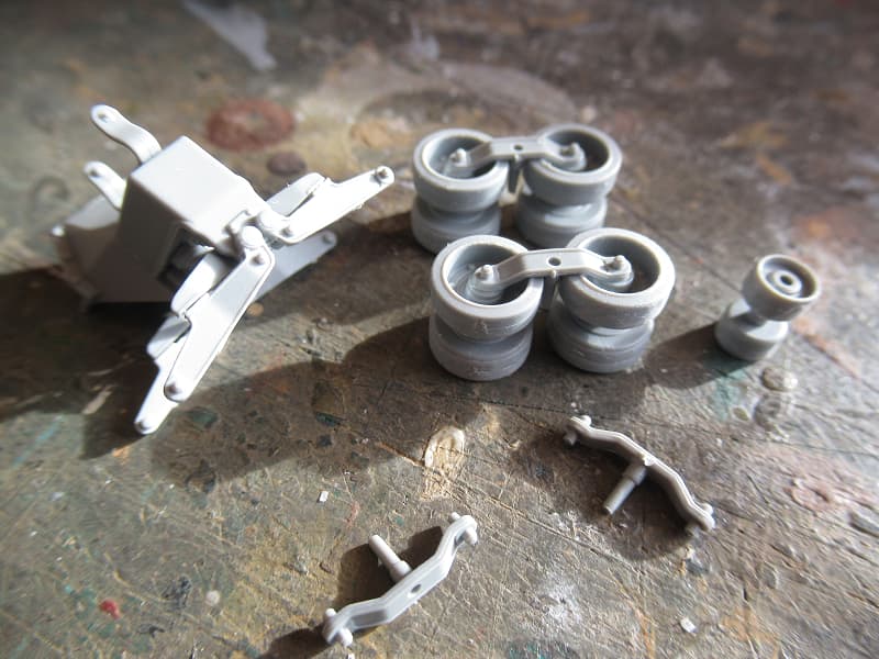
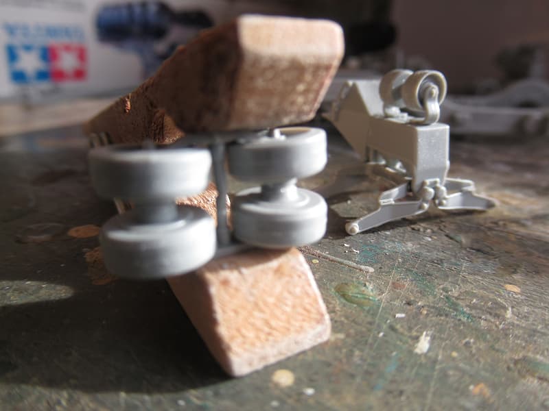
there are bolts (A) moulded in the suspension arms that suggest where the spacer bars fit. The arms need pressure to clamp them to the bogie wheels till they set.
Part of the reason that the M3A2 wasn’t put into production was that the Army had overestimated how many halftracks it needed, as there was a surplus at the end of the war Israel and other nations that needed them found large numbers in their inventory as the US UK and the Sovs looked at APCs with overhead armour and full track configuration.
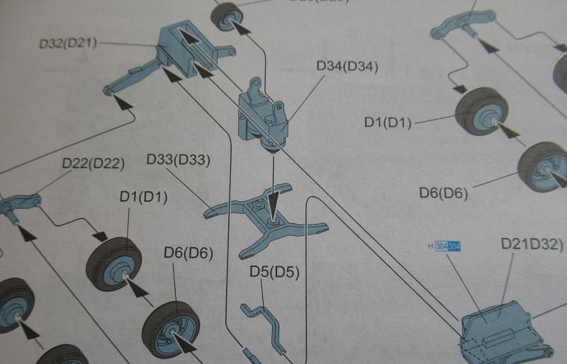
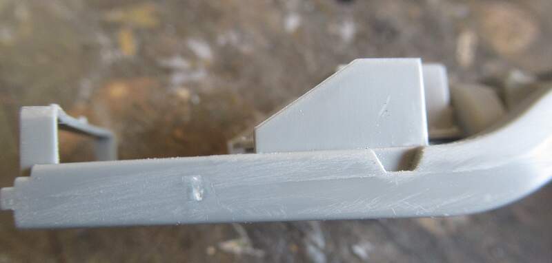
Install the front bumper assembly before the leaf springs (A32 and A33 in step 3) to avoid misalignment of the springs. The front parts would be either C20 & C22 (winch) or C21 & C23 (roller) in step 4.
If installing the roller, completely sand away the two front-facing bolted plates on bumper C26. Never existed on the real thing. This is poor DML research on a postwar refurbished vehicle.
Replace the 2x too-short connector rods on suspension part C22 with a single 1mm diameter rod of 7mm in length. (ignore this – your peg pressure fixed this)
Exhaust end cap A19 leaves a bad gap with pipe A24. Filler is necessary here. Consider adding a scratchbuilt exhaust pipe mount as well.
Upper frame C9 (in step 17 for M3) or C11 (in step 16 for M3A1) slips behind the front windscreen. When viewed from the side, it should be behind the doors and horizontal. Many modelers place this at an upward angle which is incorrect.
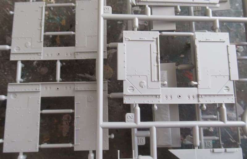
The four PE slates (MA5) for armored nose H4 or H2 are too long – hit them with two or three swipes of the file on both ends prior to installing or they will bend unnaturally.
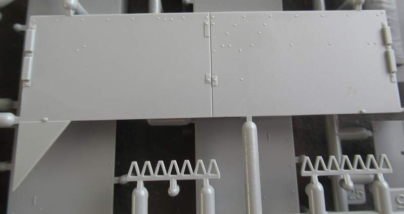
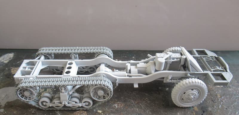
Near completion, the instructions imply you should place the engine & driver’s compartment and the rear fighting compartment onto the frame separately. This can cause poor alignment on the vertical seam between the two main upper assemblies. You should glue them together first, ensuring good alignment — then finesse the entire upper hull onto the frame. That vertical seam is very visible and misalignment there will be very noticeable.
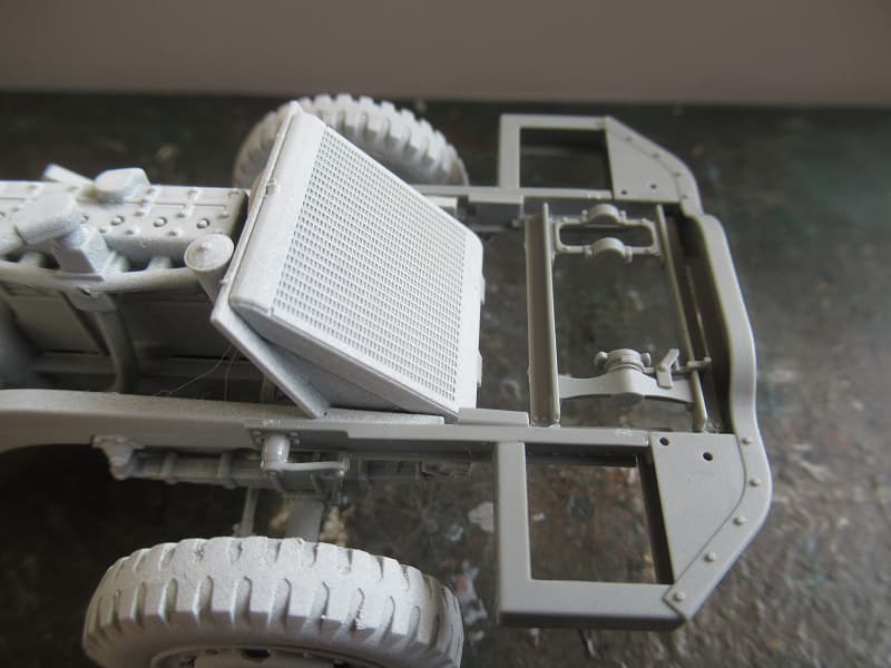
The jerry can mounts are slabs on the engine compartment sides. I always altered these.
If you more super detail/accuracy suggestions, let me know.
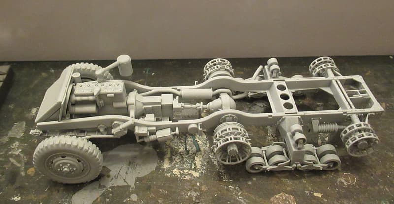
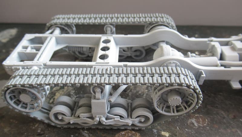
fitting the track was a fiddle. The inner band, made of hard plastic, goes on first and links into the inner gap of the idler and drive sprocket, there is very little in the way of stretch, fitting the Tamiya M3A2 rubber band track is dead easy in comparison, but they don’t have the scale accuracy with the sprocket teeth and accurate wheel rims.
the forward winch frame goes on well, I took note of Eric’s mention of the leaf springs fit, but that didn’t come up. the frame is beautifully recreated in this kit, having an upper and lower section that fits perfectly together. The winch goes in next.
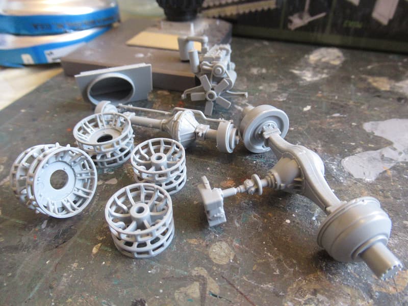
I normally leave the sprockets and idler off until I’ve painted and add them (along with the tracks) on afterward. One thing to be mindful of is your radiator housing is sitting too low. Part A26 should be vertical – yours is leaning back. Hope this makes sense.
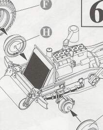
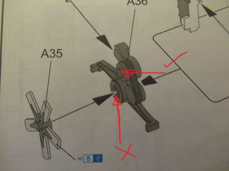
Yes, the instructions are incorrect in showing the fan attached to the lower pulley wheel instead of where it should be, the dynamo pulley, this interfered with the radiator fit, why a dry fit of the cab is a necessary step. Corrections made.