Hi all,
As I’m going into my second year of working on HB’s kit #82408, I guess I ought to explain my extremely slow way of building: In a nutshell, it’s too much research plus the urge to translate all my findings into the model, aka AMS. Having a number of other interests and a beloved wife doesn’t speed up building, either.
In this case, research started with Tankograd’s No.6002, “US WWII M4, M5 & M6 High Speed Tractors” and Ampersand’s Doyle/Stansell “High Speed Tractor” (revised ed.) plus lots of pictures on the web, not least at primeportal and Toadman’s tank pictures.
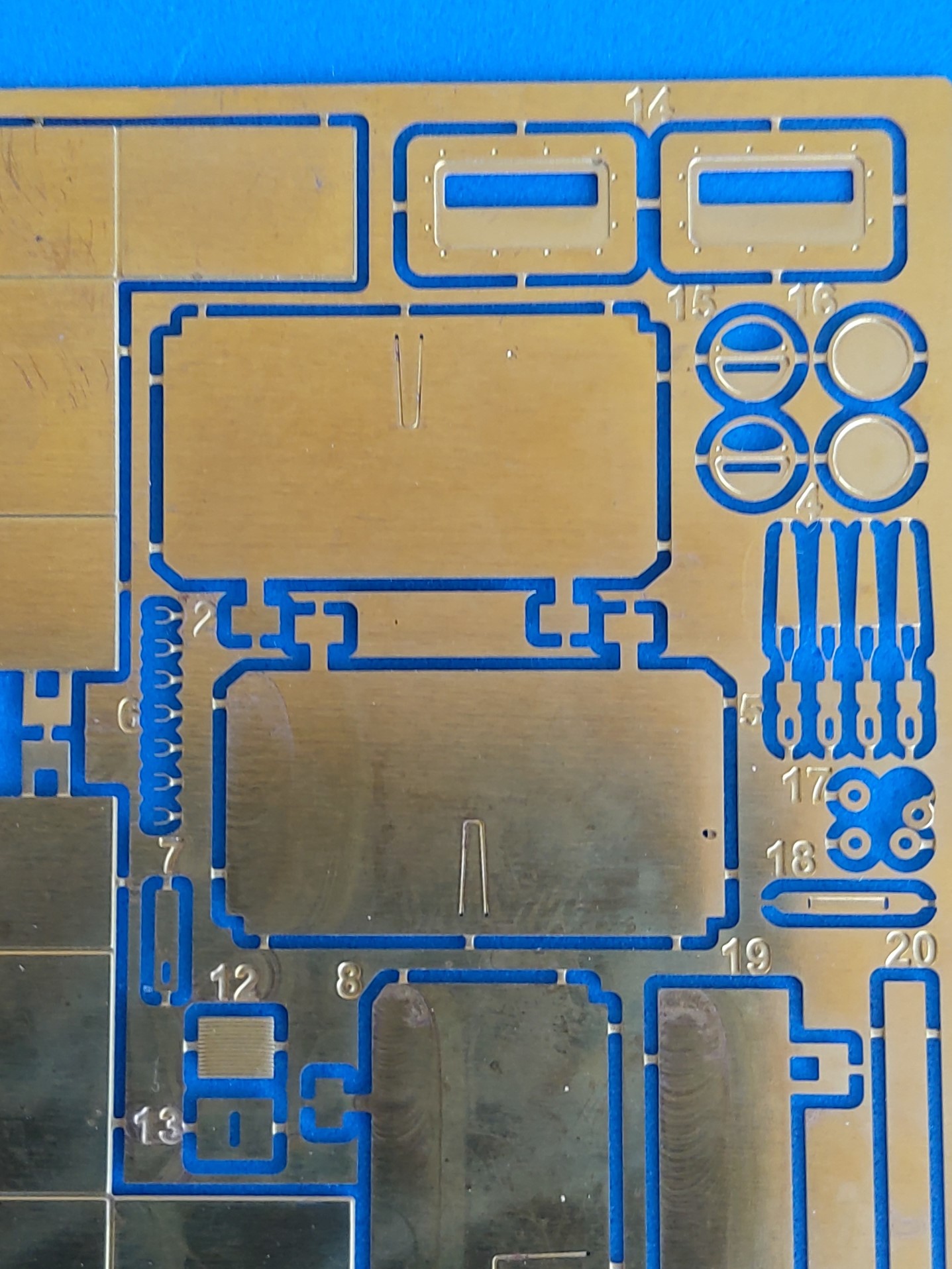
As Eduard’s PE set is OOP, I settled for PART #35-212. Unfortunately, you aren’t told that the set is for the M4 in the small-caliber livery, so I didn’t get anything for my ammo box variety. On the other hand, however, my package contained the main PE sheet twice: once as advertised, plus another one that was mis-etched in that it was only 95% ok. Which left me with lots of excellent parts, like all stowage boxes with operable lids and hasps - wish all PE makers would dispose of their scrap like this!
The lower hull went together easily enough after filling and sanding a lot of annoying push-out marks. On the rear wall, I overlooked that the “frame” around the central winch cable outlet belongs not to the outside, but to the inside. But the tow hitch, of course, had to be made operable. On the front plate, the gun emplacement hitch received a hitch pin plus (later) arrester pin and PE securing chain.
The running gear, too, went together without problems, but the instructions don’t tell you that the volute springs’ thinner ends have to point to the rear on both sides and that a hole of about 1mm should be drilled into all end caps of these springs. The suspension halves of the rear idlers leave ugly open spaces around the central nuts that had to be filled, and the “stars” around the nuts were added from wedges of .25 x .5mm plastic strip.
This much for a beginning. Comments and criticisms welcome,
Peter
4 Likes
Start the stash small:
And build up the lifetime supply:

I have this one in the stash, with the Eduard etch fortunately, so I am interested to see how you progress Peter. Those gaps look ominous for the rest of the build.
Well, my stash consists of less than 30 kits (not counting those that are collector’s items) - but I don’t believe I’ll be able to finish them all in this life. Although I hope that the majority will be better than this M4 HST:
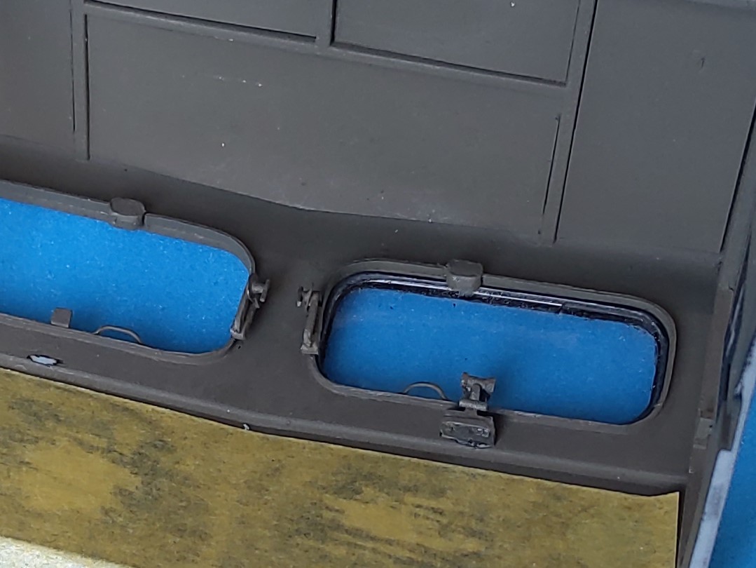
Being a very unsystematic builder, I next turned to examining the cab shell. Please correct me if you think I’m wrong, but in all the prototype pictures I could find, the window openings go down to the bend in the front wall, and the side wall segments between the seat rows are at one height with that bend, too. Looking from the front, the distance between the headlight top and the bend is remarkably bigger here than on the prototype, where on the inside, the panel with the driver’s controls reaches right up to the lower window rims, with these frames protruding to the inside.
To me, this means that the level of the front wall bend is about 1.5mm too high, but I couldn’t think of a way to correct that. The windows, however, could receive a styrene strip on the inside of the opening for
adding scratchbuilt wiper motors, locking mechanisms and closing handles.
As for the windshield arms, there’s another problem in the form of the missing recess between the panes on the inside, which makes it near impossible to mount them correctly.
HB offers two versions of them, plastic (A20/21, ignored in the instructions) and PE. The problem being that in plastic you only get the stretched pushed-out version, nicely different for right and left side of the panes, but without the circular arresting mechanism plates. These are present in PE, as are the arms in both open and closed versions – but the arms are all made for the right hand sides of the panes! I cut apart the plastic parts and re-cemented them into the closed form, adding the PE circles plus small pieces of stretched sprue as locking grips.
As the positioning holes for the tools on the roof go through to the inside, thin styrene sheet was glued to the ceiling.
Can you imagine how long it took me to fix all this?
Peter
3 Likes
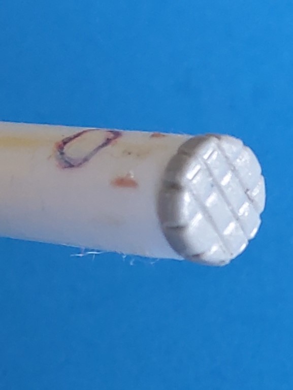
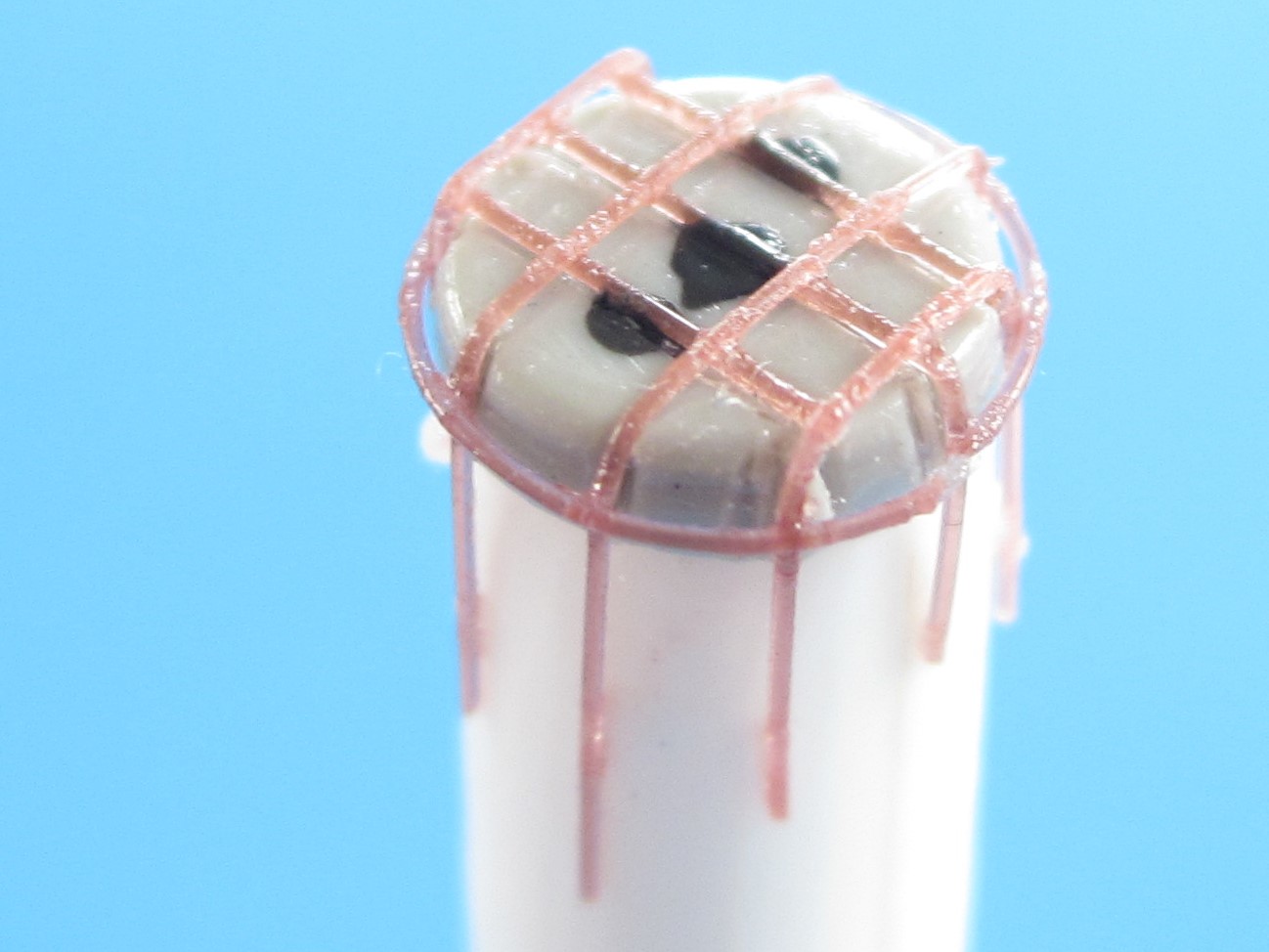
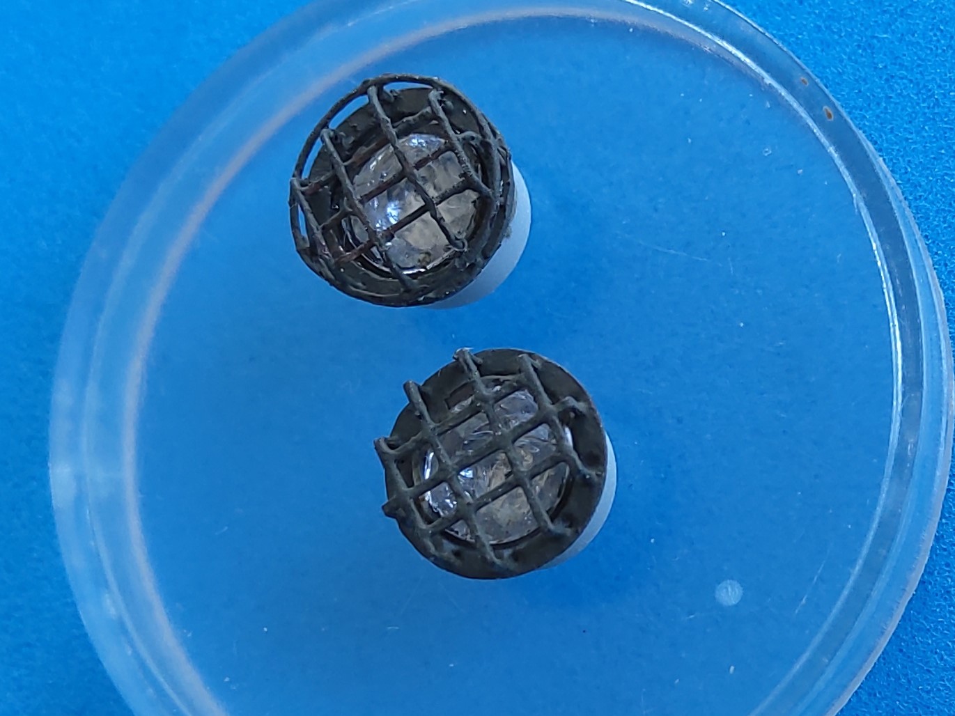
Did I mention that I’m a very unsystematic builder? As soon as I find an interesting detail, I start reproducing it. With this kit, for example, I found part C54 on the sprue, but no mention of it in the instructions. I decided it must be a bending aid for the headlight brush guards, which isn’t needed for the PE parts of kit and PART, but those don’t offer the ring around the braces. So it was cemented to a piece of sprue and received several coats of Future before thin styrene rod was used to make new “cages” for the headlights. For the lamps on the ammo box, I took the kit PE, as I intend to cover these with “hoods” from thin silk fabric (once I get that far). They all received reflectors from thin aluminum foil.
Peter
11 Likes
Cages look fantastic.
That is a brilliant idea. I need to make some cages for lights for my Aussie MRV (Shelf Queen) and my sad attempts at wire and solder killed the build. With all the resin casting plugs I have, making up a reverse master for stretched sprue may be my solution. Thanks for posting this Peter
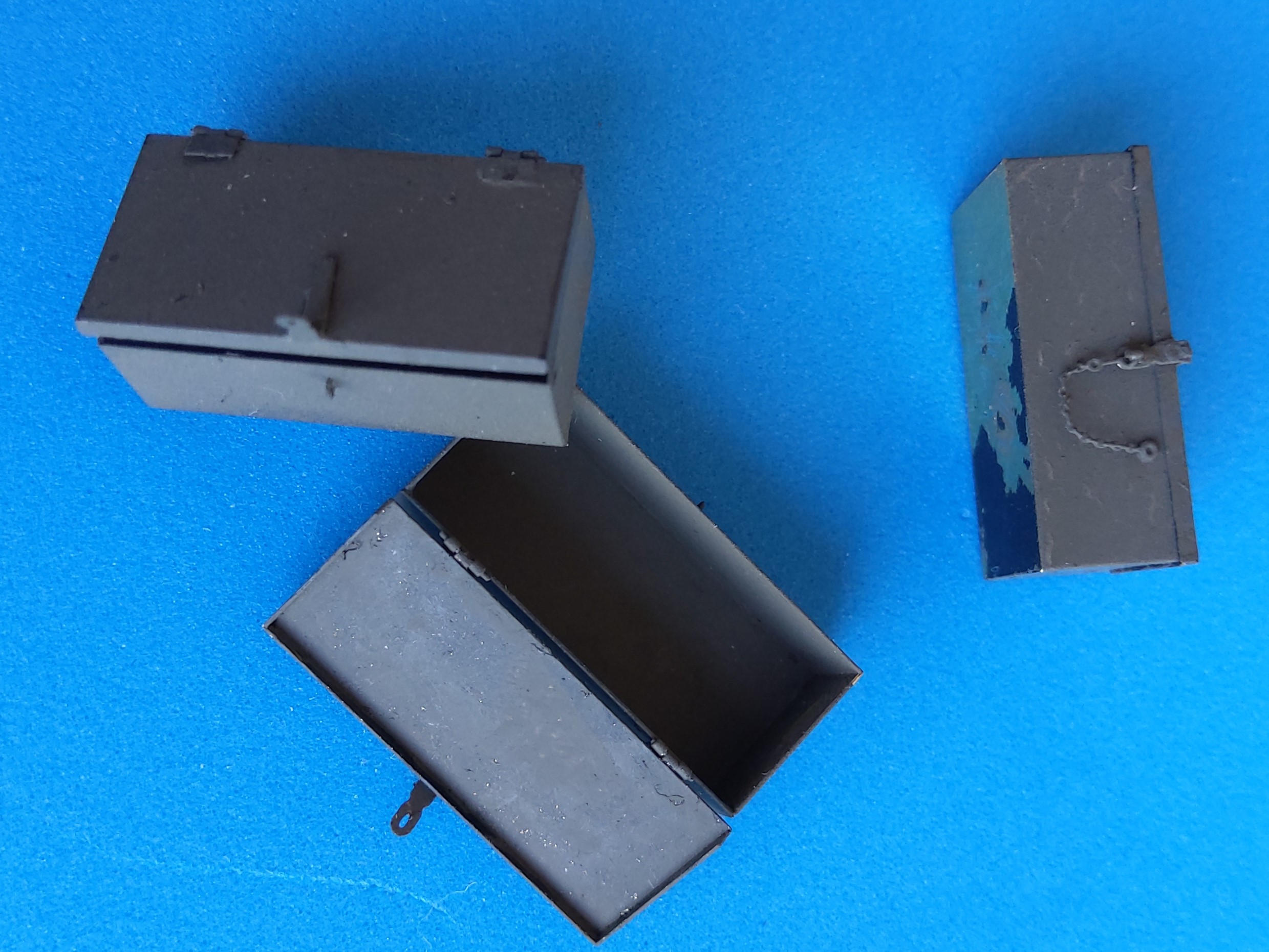
Another time-consuming detail were the PART stowage box replacements: separate lids with functioning hinges and latches. If you call this over-engineering, I’ll fully agree, but I had them on the fret, and they would look better than the kit plastic, so…
Right away something that goes for all versions – kit, Eduard, and PART alike: On the prototype, the box on the engine roof is mounted with its hinges towards the rear, so it can be opened from the manhole in the cab roof. This reason escaped HB, so they turned it around, and both PE makers followed suit in their instructions – don’t believe them.
Folding and cementing boxes and lids was easy, but their hinges were something else, as they’re of scale thickness. I “wrapped” them around 0.2mm wire with tweezers and then bent and cemented their “fastening plates”. This was even more fun with the latches because of their minuscule size. If you have this PE set, make sure that you join the latch parts (# 4,5) before adding them to the lids, as lining them up is much easier without the lid hanging off them (this advice is based on experience). The securing chains offered no problem, but the eyes they go into are highly fiddly, to say the least: just an etched “u” that you have to affix (# 6)!
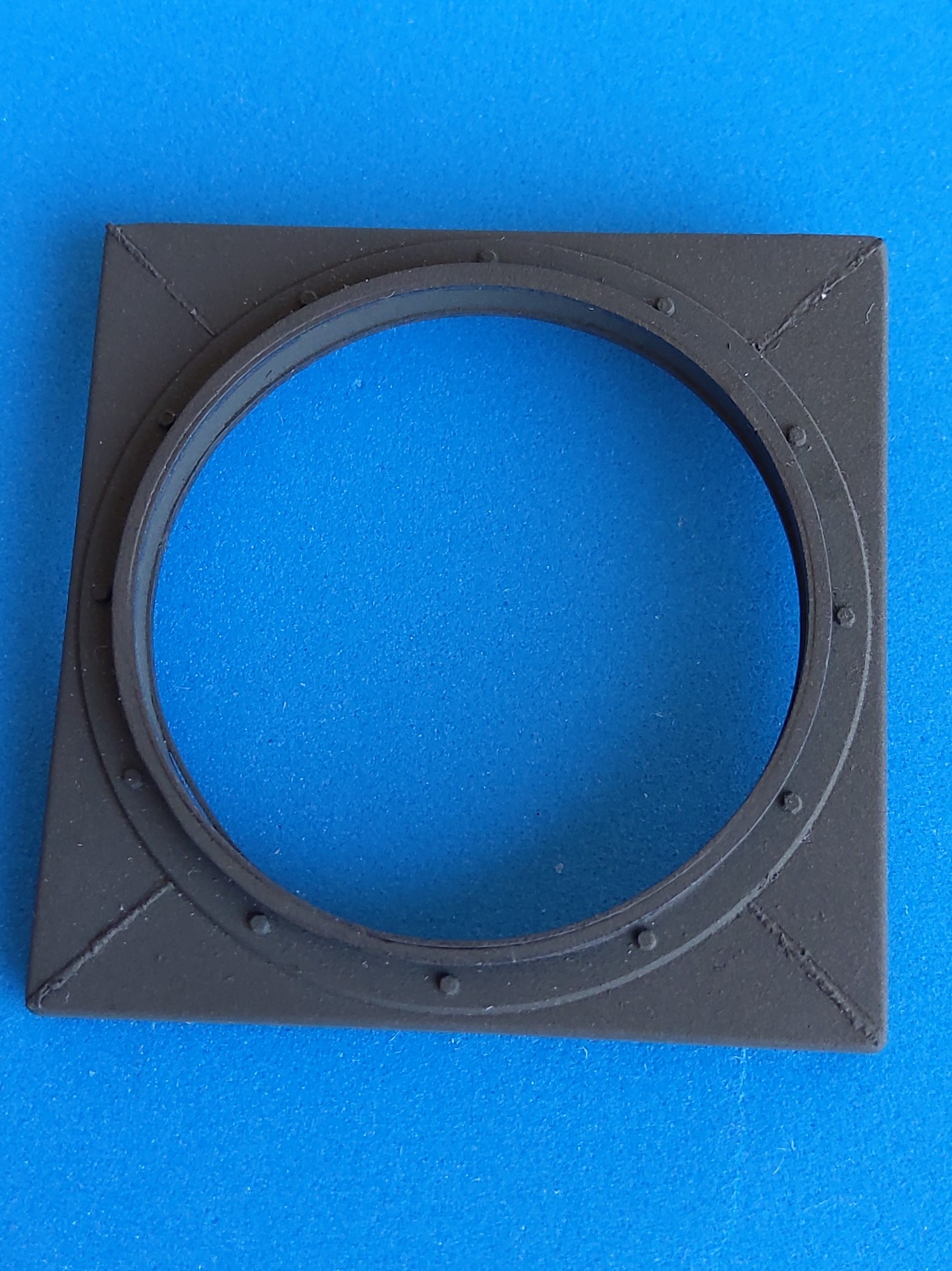
To recover from this ordeal, I turned to the manhole. That doesn’t offer the weld beads into its four corners, so the grooves were filled with stretched sprue that was structured with a knife after being softened with liquid glue. Lengths of 0.25 x 0.5 mm strip were cemented inside the MG ring to represent the roller tracks there. Parts B17,18 for the MG skate were so huge and so badly detailed that I decided to leave them off, as there was nothing for them in the PE set either.
Have fun, it’s a hobby!
Peter
3 Likes
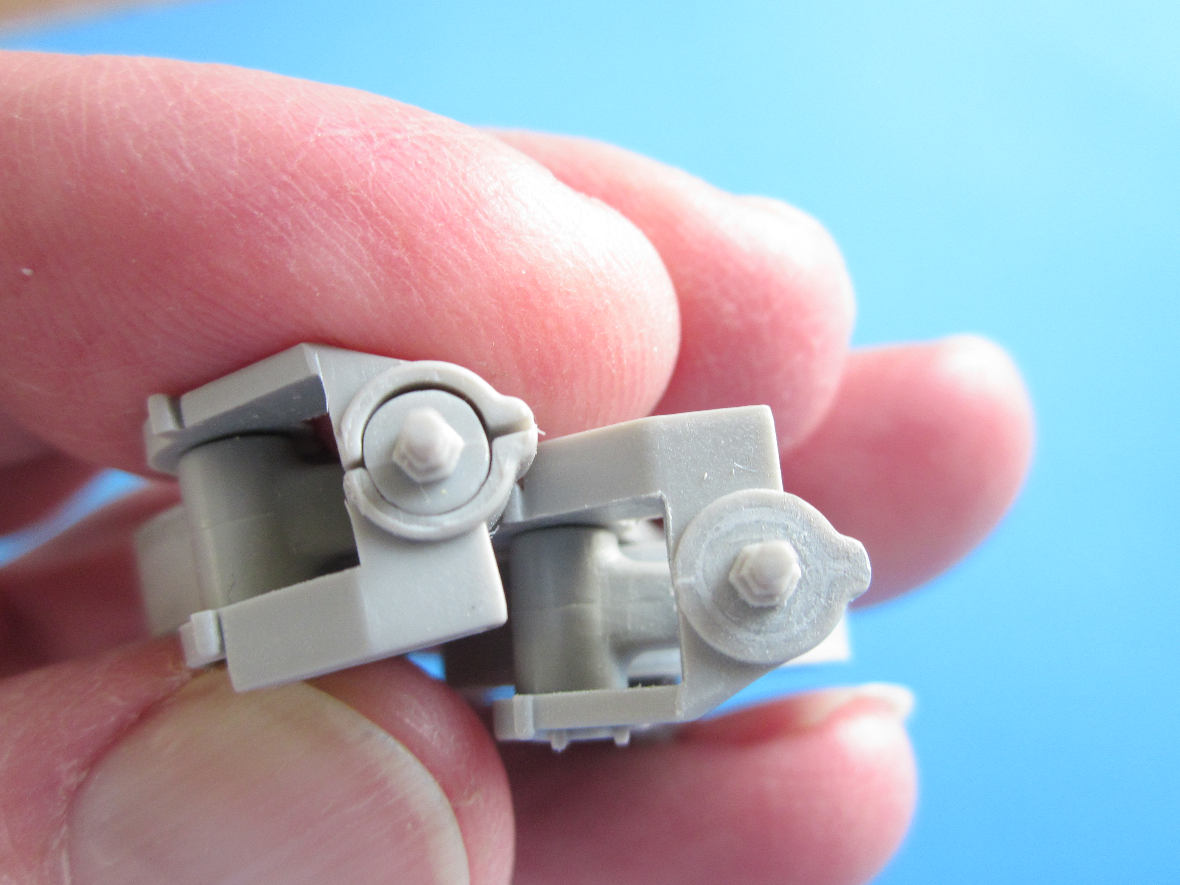
I’m working on this one as well. Watching with interest. I’m stumped on how the front sprockets attach to the hull. Seems to be something missing in my understanding of the instructions. I’ll be watching/lurking from the third row back.
The tip on using the part to form the light guards was most definitely worth getting out of bed for. Thanks!
~Phil
Phil,
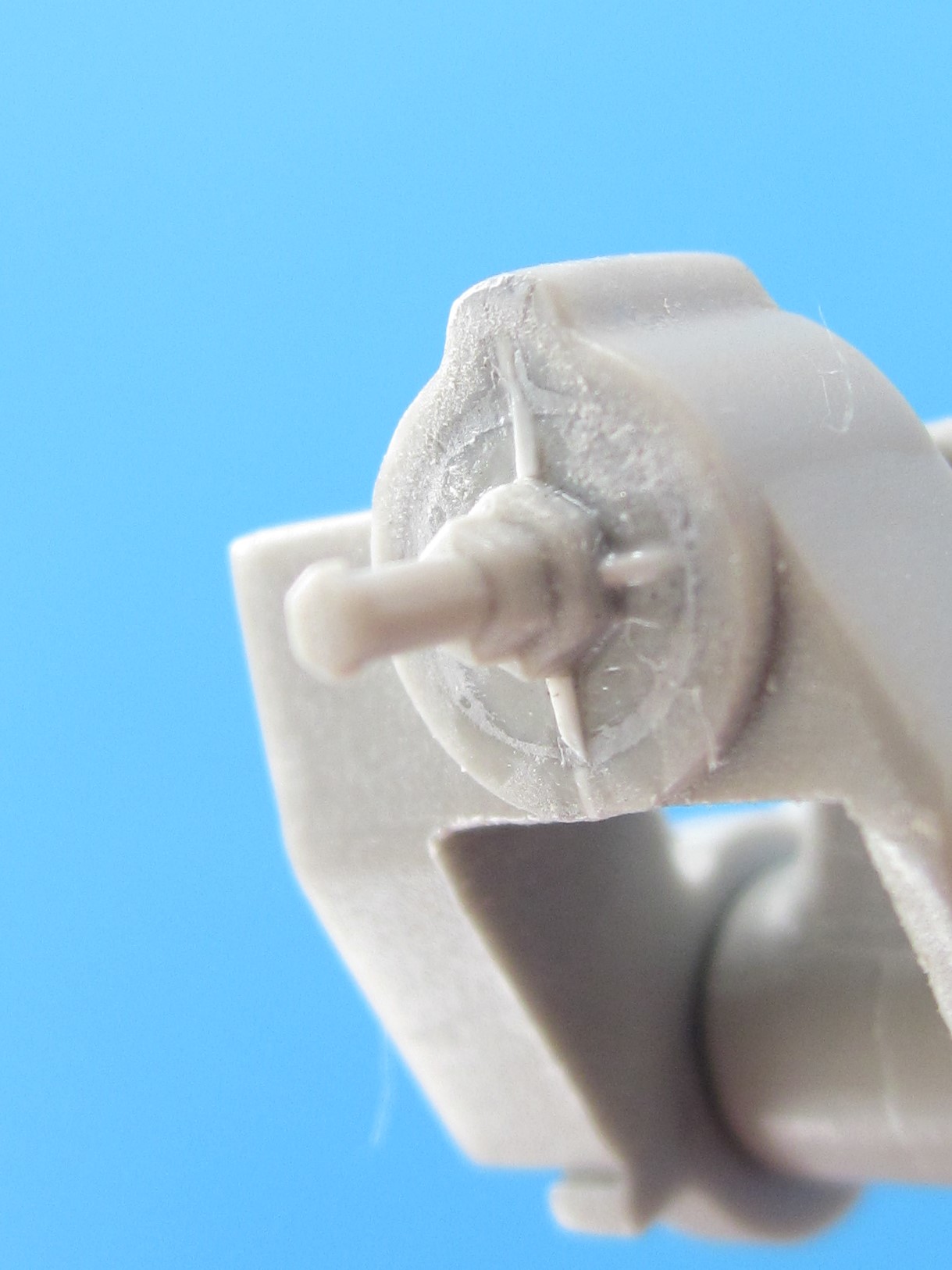
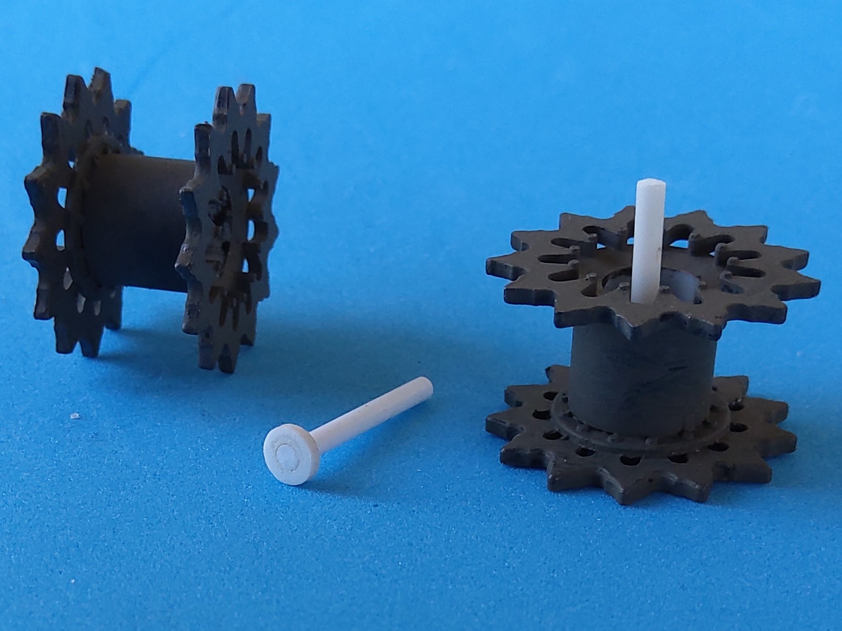
I had similar doubts, and especially to make mounting the tracks easier, I’ve taken 1.5mm plastic rod and cemented it into a disk of 1mm sheet that fits into the recess at the bottom of the sprocket’s hollow. Holes of corresponding diameter were drilled into the final drives, so now I can simply push the sprockets in place.
HTH,
Peter
4 Likes
Oooh, I like. Excellent resolution. Much more precise and elegant than the matching lumps of epoxy putty shoved into the sprocket with some metric precision that I had in mind. I wonder what the real answer is though…P.F.M. I guess. Good luck!
Nice attention to details there Peter.
You can keep those number 6 parts… no thanks. You are a game man as far as I am concerned.
No way I would get those to hold in place. I’d drill a hole and use fine wire to make the loop. One long arm on the loop, with plenty of space to rest the chain on so it wouldn’t fall off, and insert that until the short arm is in place. Then the arm can be snipped off inside later.
For the time being, #'s 6 are holding on with super glue gel, and I don’t intend to play with them any too much, but keep my fingers crossed.
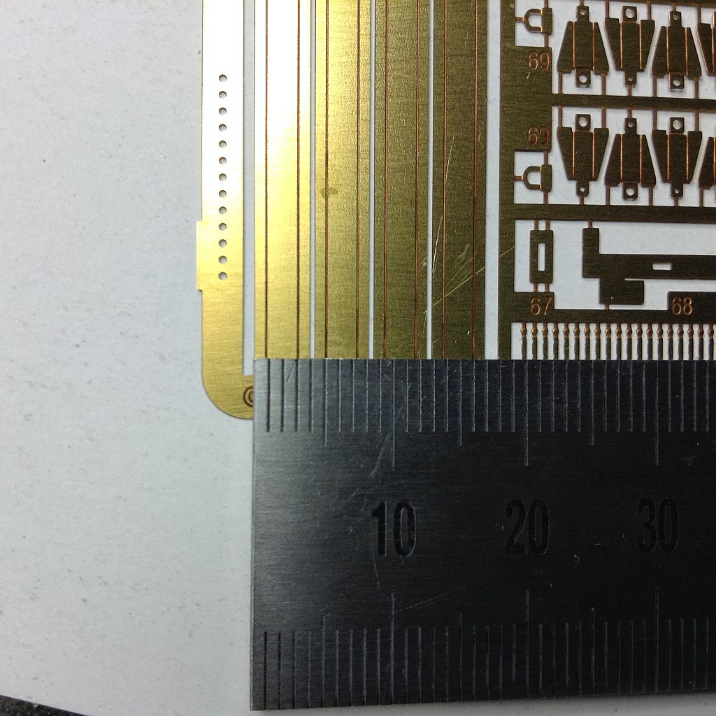
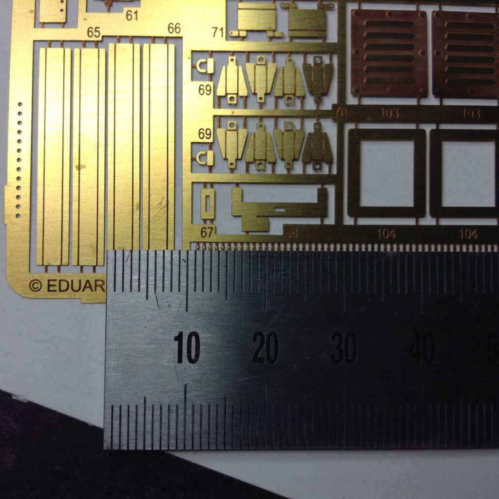
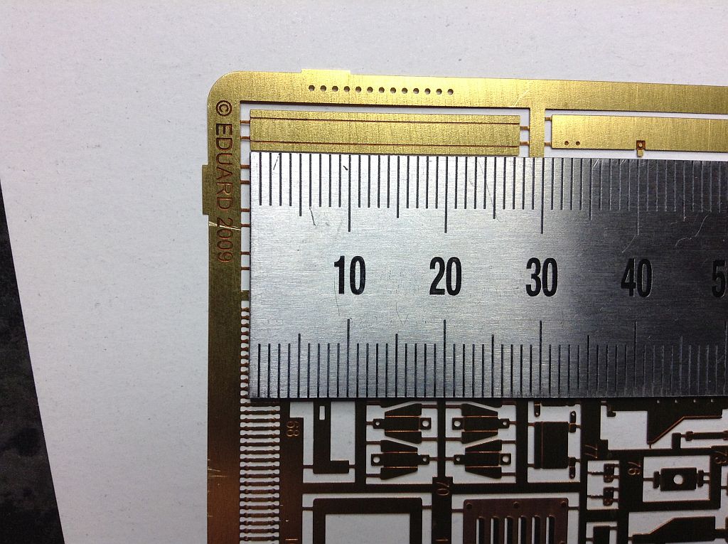
You could do me a favor: you mentioned that you have the Eduard PE set for the 155mm ammo box variety. Would you please measure Eduard parts 65 and 66, the “channels” on the sides of the lateral compartments, so I could bend my own or sand them from Evergreen profiles?
Thanks in advance,
Peter
@PzAufkl
A picture is worth a thousand measurements… but not when you have lens distortion… the length looks a little off in the pic.
#65 4.00mm x 28 mm with the bend a touch under 1mm
#66 4.00mm x 28.5mm with the bend a touch under 1mm
1 Like
Thanks a lot, that’s all I needed!
Peter
One question on the sprockets… are these the kit items? The M4 HST used the M4 Sherman sprocket and road wheels, not the Stuart ones. The tracks they used are also of the types for the Sherman, not the Stuarts. The vinyl tracks in the HB kit are supposed to be M4 type but are way too narrow and the sprocket is therefore the same. If you are going to use AM tracks, you may want to check that.
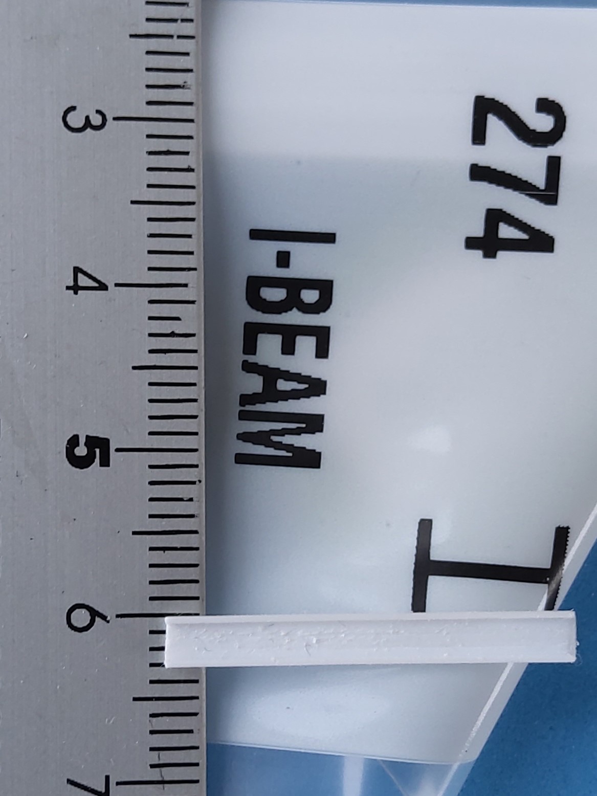
Evergreen’s 3.2mm I-beam can be cut down into a channel and with some sanding be reduced sufficiently close to the measurements of the Eduard parts - bingo!
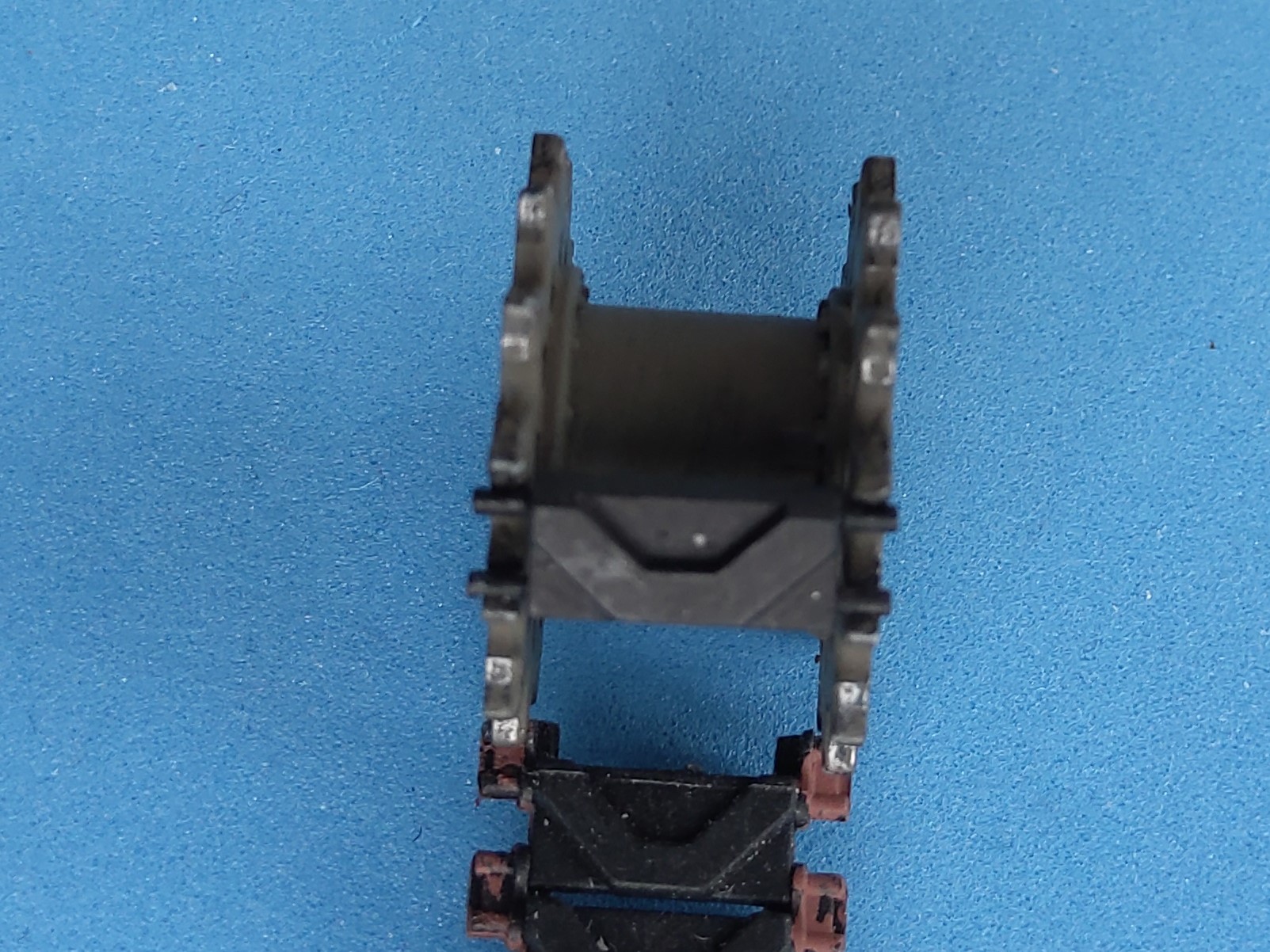
The sprockets are from the kit, as will be the tracks. A fellow modeler gave me some T-48 indy links for the spares stowage rack (sorry, forgot what brand), and they’re absolutely compatible with the kit stuff, so I don’t see that as an issue - 'nuff other problems! Photos to follow once the sun is up again.
Peter
1 Like
A test channel whittled from I-beam:
And the indy link on a kit sprocket, with kit track underneath:
Peter
1 Like
Interesting. I actually just checked the kit tracks against a set of Model Kasten T49 and Bronco T48 tracks and you are right. They both have track pads the same width as the kit tracks. I must have had the sprocket issue for some other kit mixed up with this one, or the review I read a few years ago had it all wrong. Thanks for checking for me.
Nice work on the channel too. A bit of work but it will add to the finish.
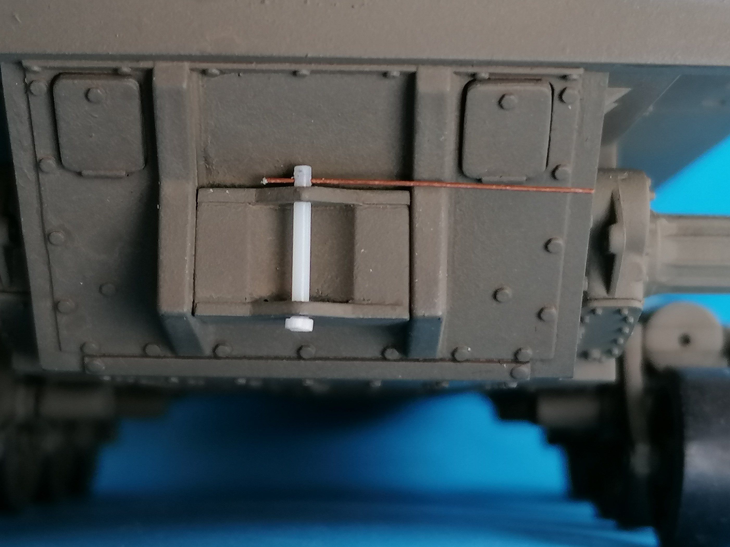
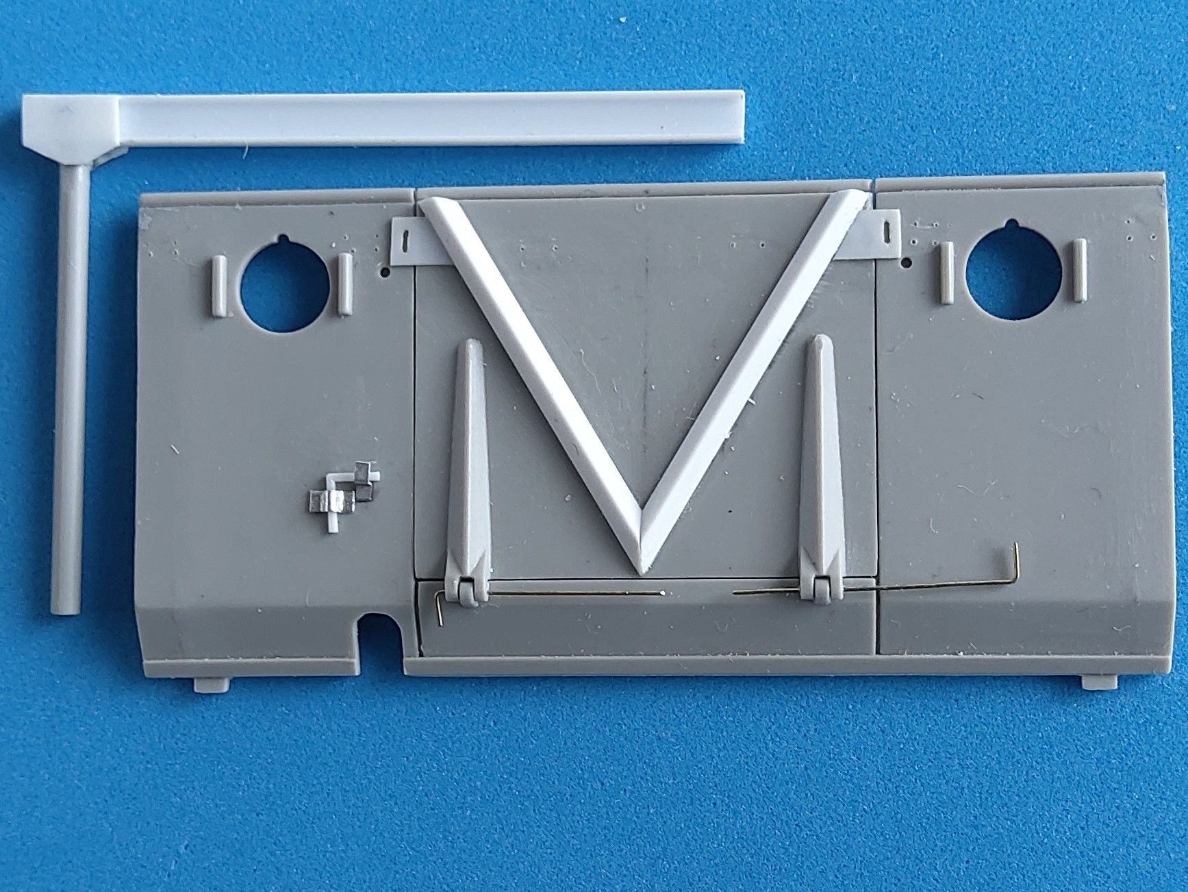
Actually, I had bought the I-beams because I couldn’t rectify the deep ejector pin marks on the ammo crane and had to make a new one. Can anyone please tell me where that “Lock Pin” on the left will go in, to lock what, once it will have its securing chain?
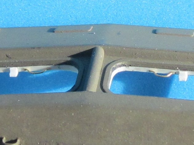
While in the area, I noted that the strengthening “V” on the hatch was incorrect in that it didn’t go from top to bottom but was about one mm short on both. Evergreen 1mm L-angle to the rescue. The hinges could be drilled through without trouble.
And the tiedowns should all be at the same level, on all four sides, i.e. six on the front wall, too. Below these tiedowns, near the bottom of the front wall, HB have molded a ridge that I can’t find in any prototype pics, so I sanded it off.
2 Likes