Well, it took me a while to regain my self-confidence regarding paints, and then Real Life stepped in my way, so there’s been less progress than I had hoped for:
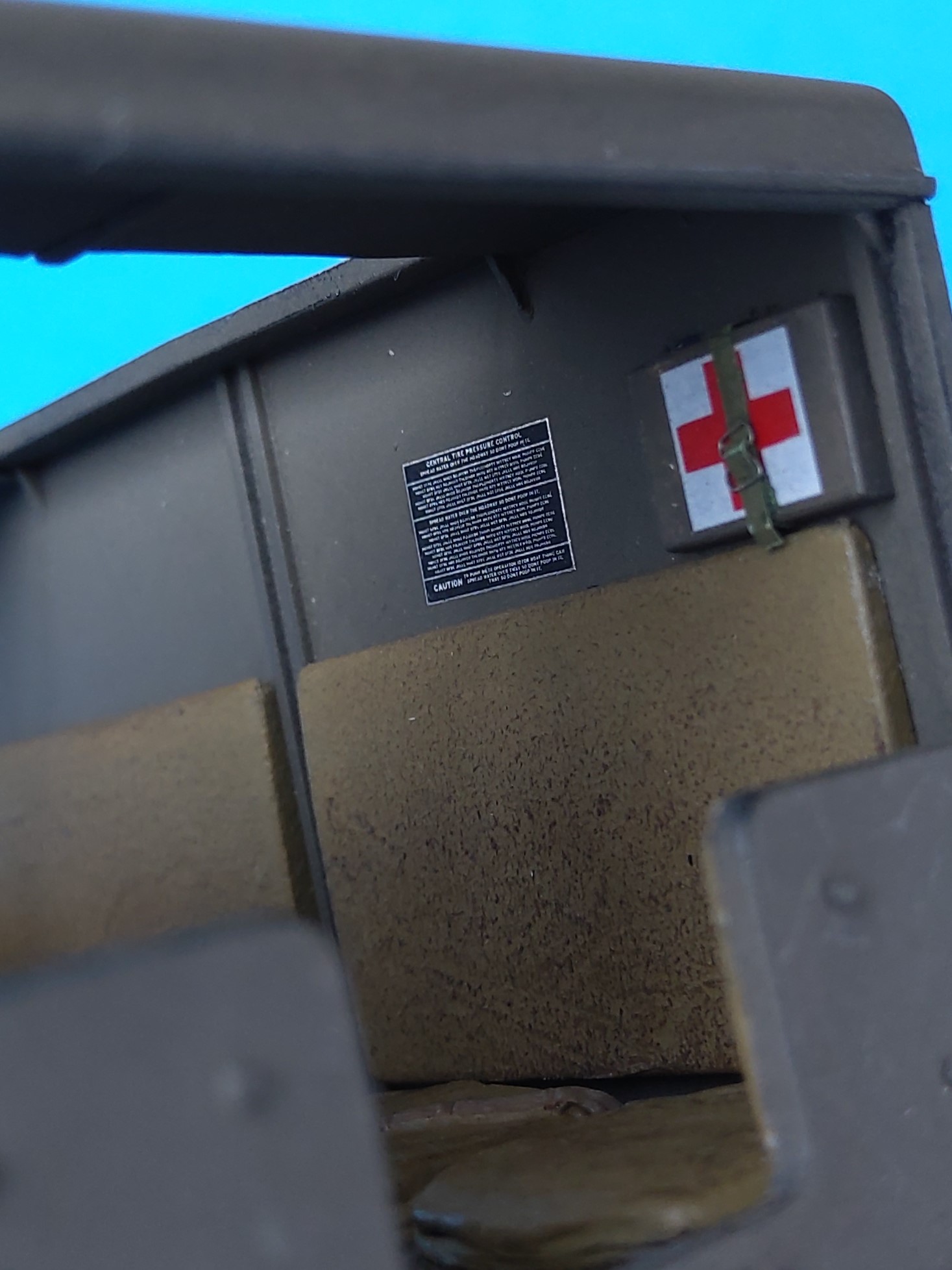
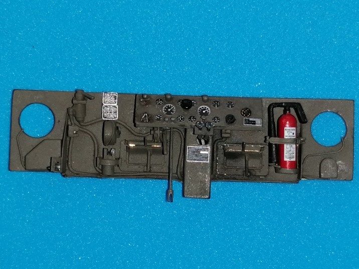
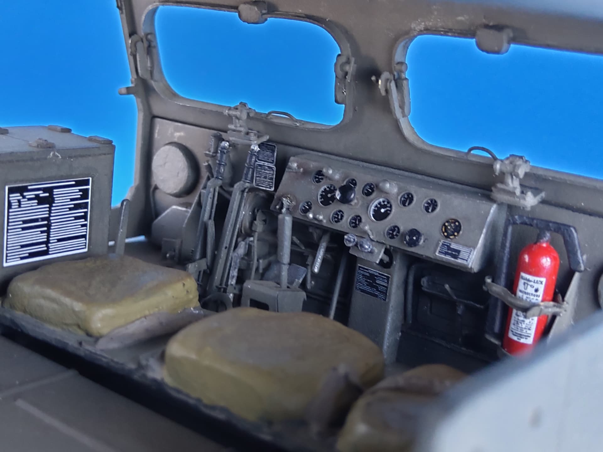
The placard decals are mostly from the Archer sheet, the bezels show the PART film.
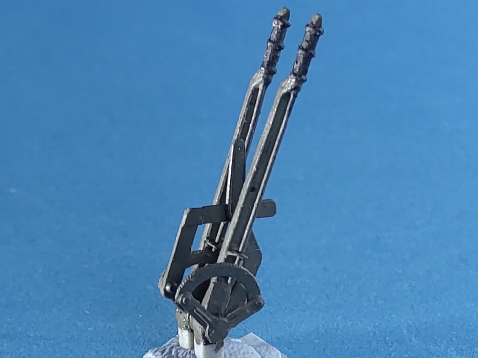
The steering levers received PART quadrants (w/ incorrectly many too small teeth) and scratched arresting rods. Between them, the scratchbuilt two-part PTO lever was placed.
Just saw this thread as I am currently focusing on modern armor only but I must say I am being blown away from your skills and creativity. Those head lights screen guard build… crazy. I love it! Keep it coming sir!
All back rests and lateral pads had one ply of a paper handkerchief added, affixed with dabbed-on thin liquid glue. The First Aid box received a decal from spares and a fixing strap from onionskin paper with a figure-8-bent wire buckle.
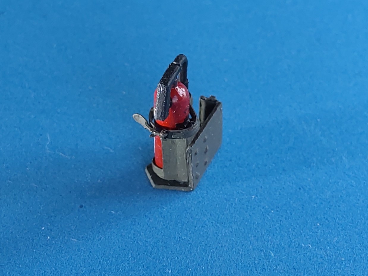
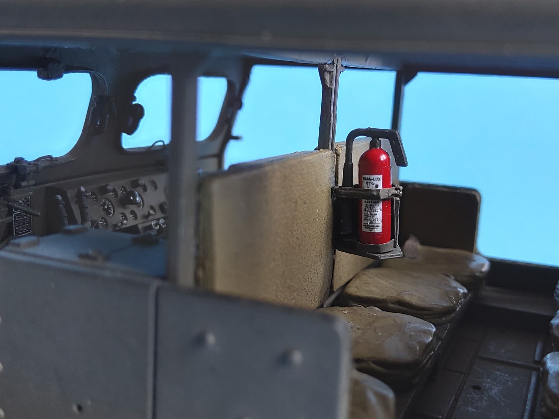
The second fire extinguisher with its PART clamp was set on a platform scratchbuilt after Eduard part # 80, which also brought the contraption into the correct position on the partition wall:
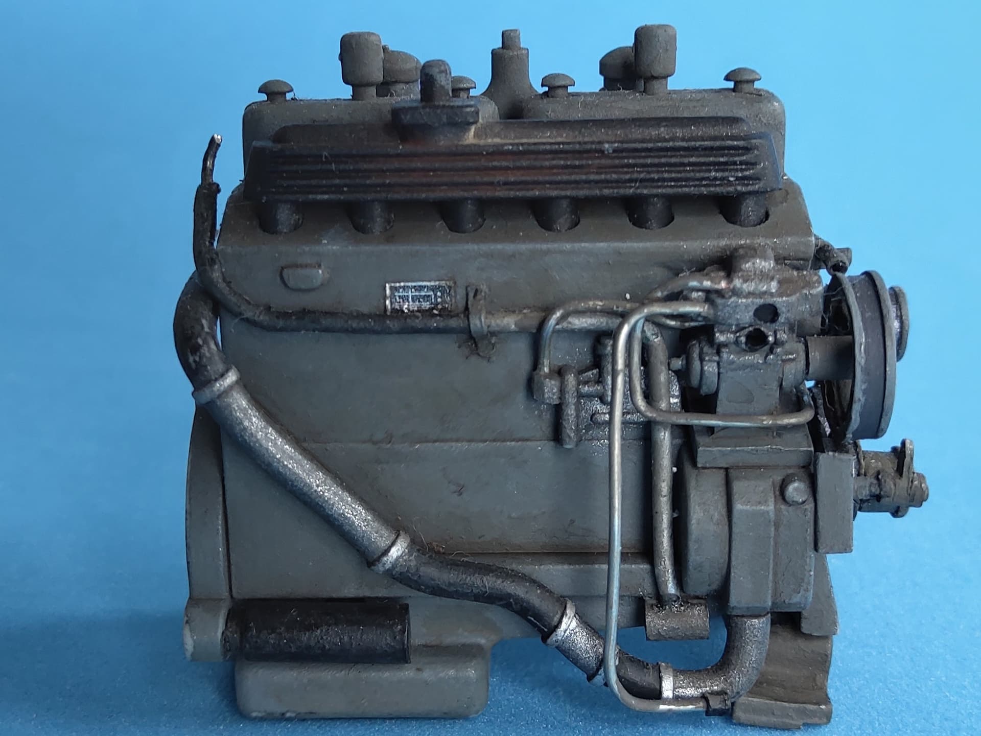
Which pretty much completed the cab, so I went on into the engine room.
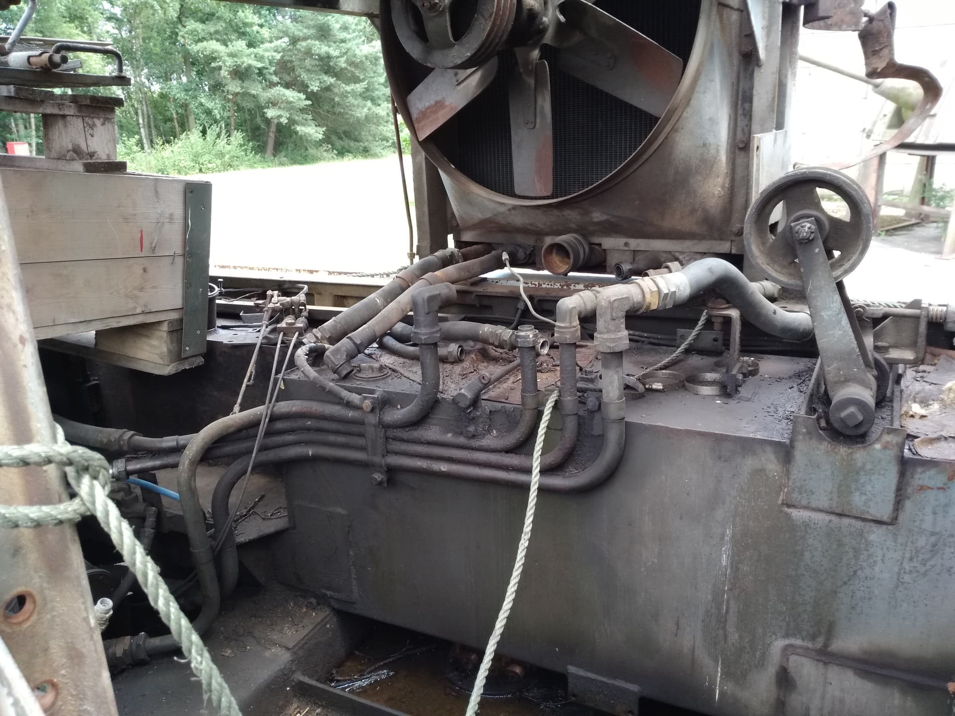
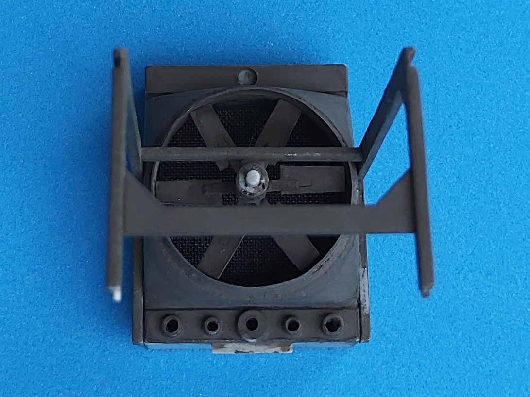
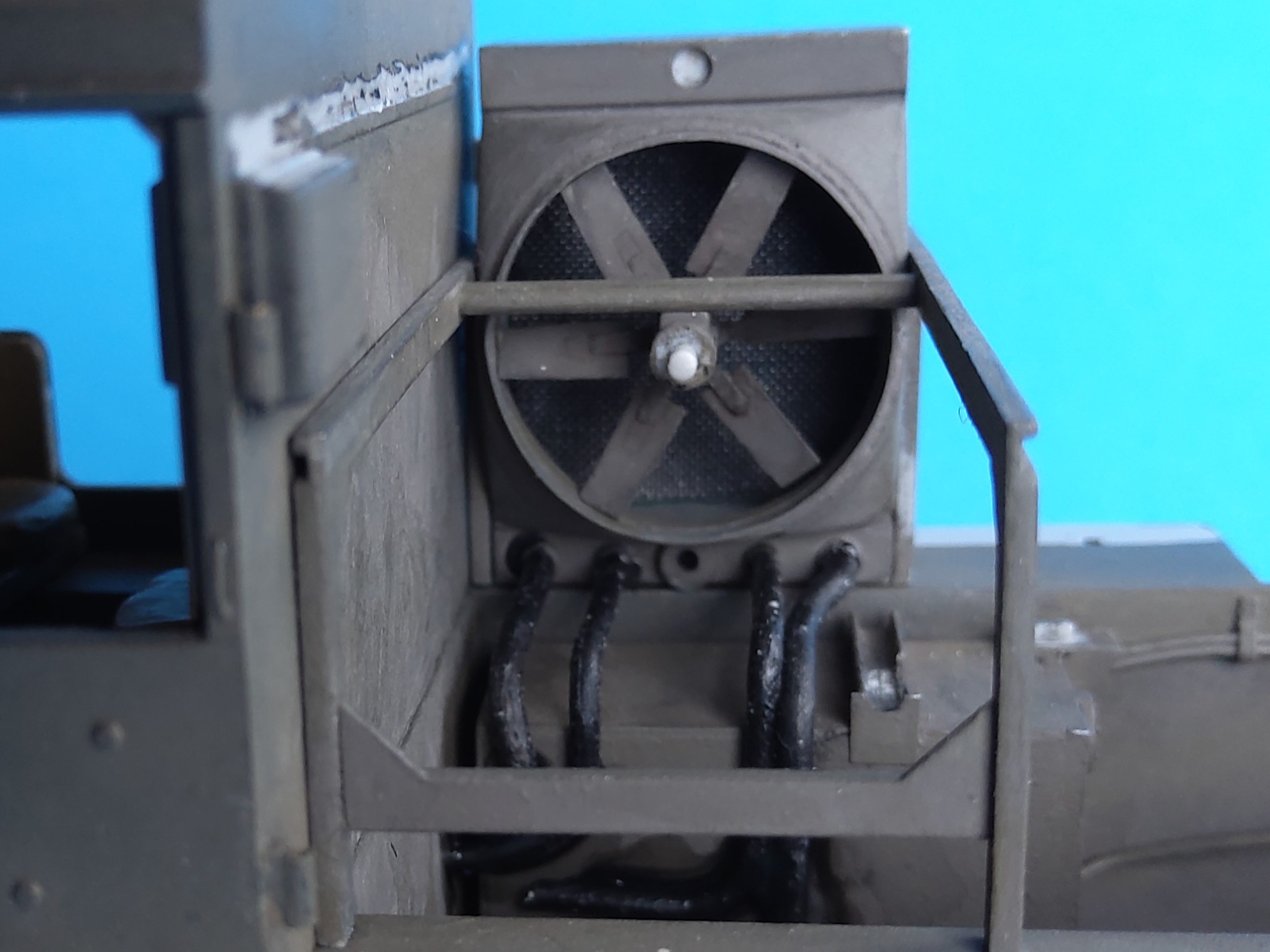
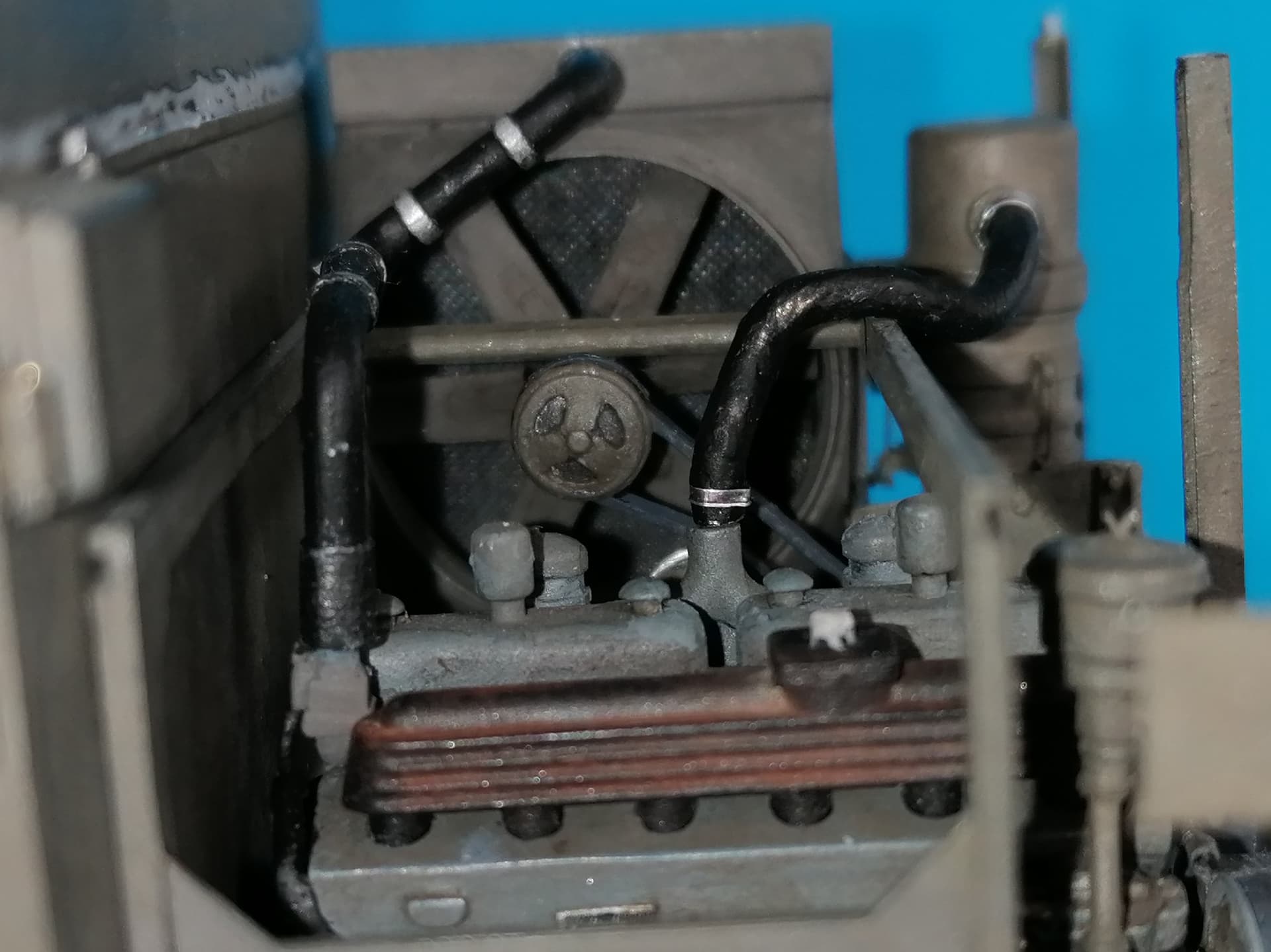
Fortunately, I had taken a picture of the fan some years ago at the Belgian Brasschaat museum:
The radiator housing had its plastic fan shroud replaced with a more scale thickness plastic one, installled around a provisional sheet aluminum former.
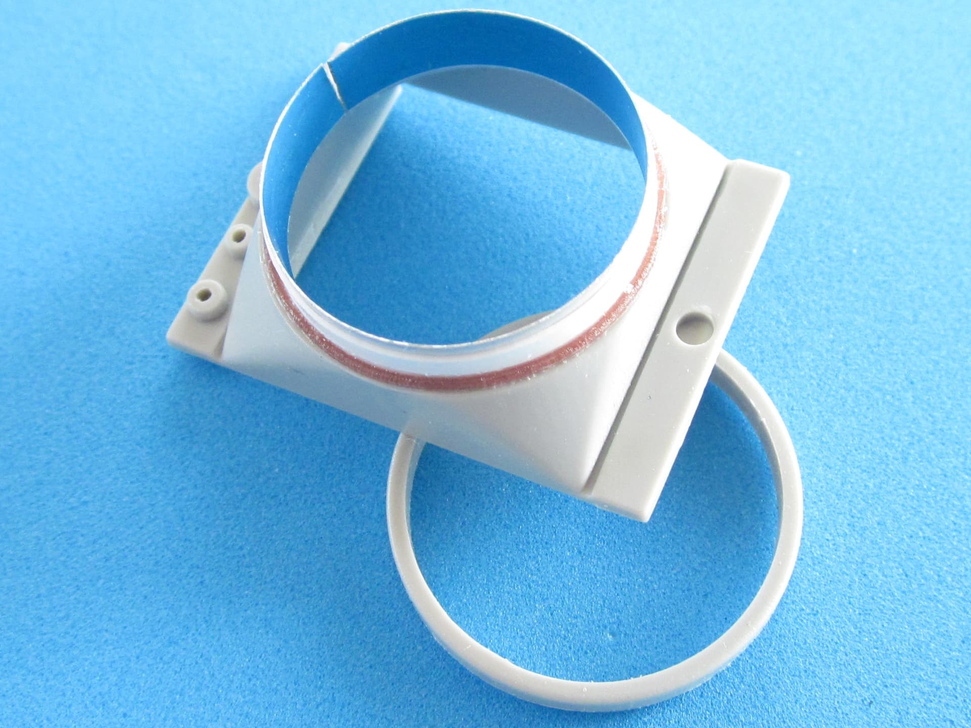
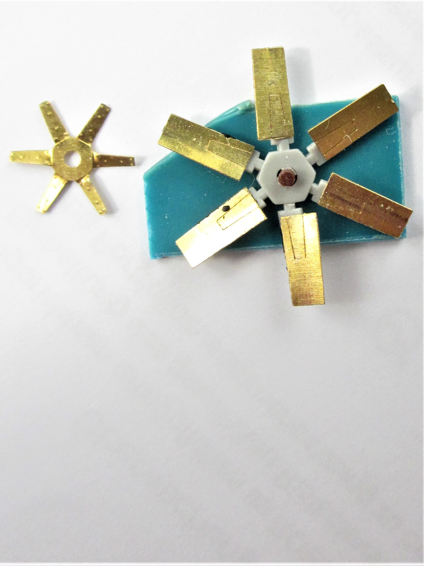
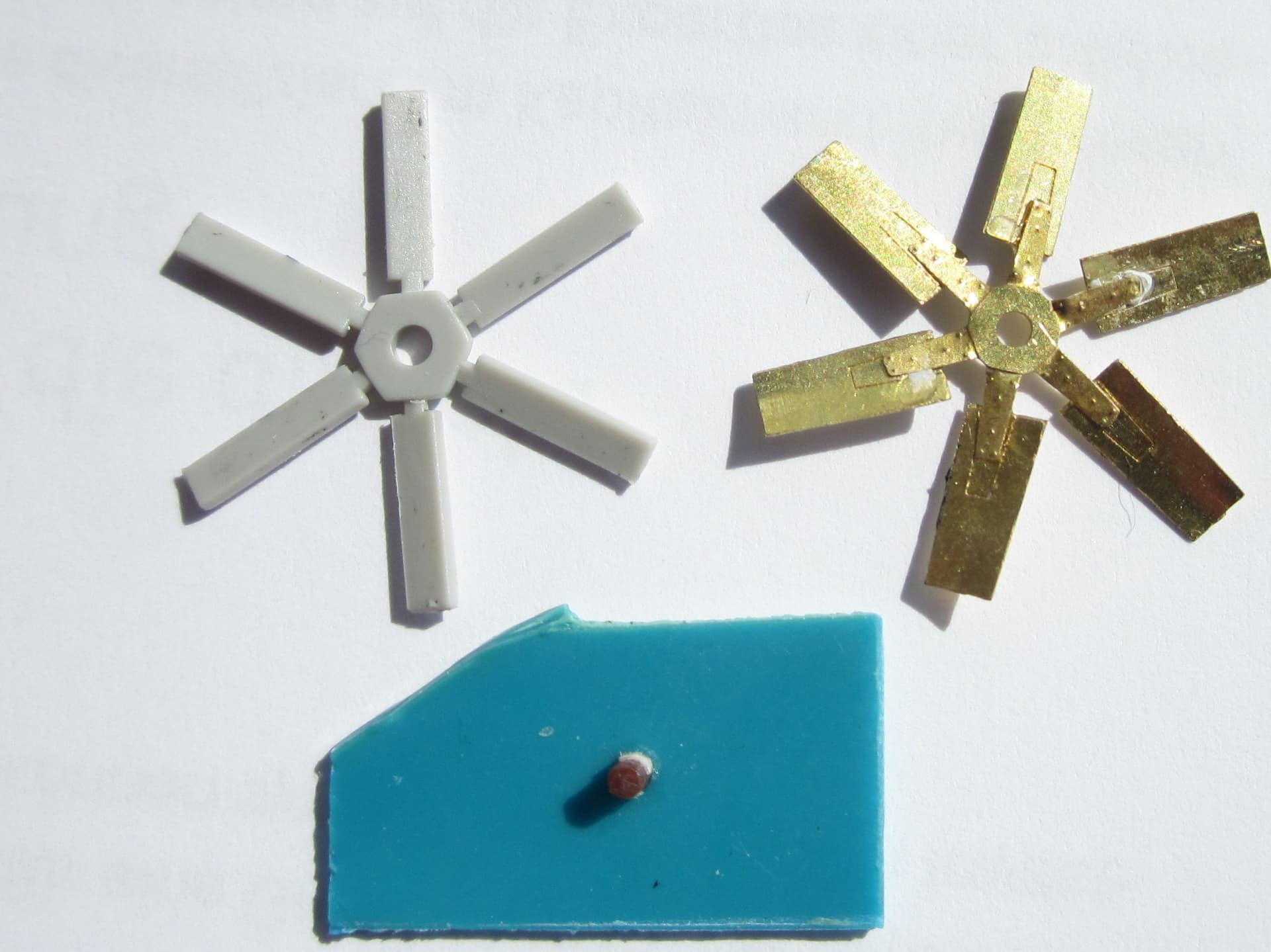
The kit fan very much needed replacement by PART, but at least its blades had a correct pitch. The positioning outlines on the PE parts were incorrect in that they would have you build a fan with a too small diameter. So, I made a small jig that allowed me to white-glue the PE to the plastic with correct pitch and then twist the central star’s outriggers correspondingly before adding it.
Before closing the radiator housing, I cut a piece of plastic sheet of suitable size and glued a piece of brass grid to it to represent the radiator’s mesh (and forgot to take a photo). The five “nubs” at the housing bottom were drilled out so coolant hoses could be added later.
The four thinner coolant hoses are insulated copper wire, the channel on top of the fuel tank is a sheet replacement that received a cutout for the “Fan Tightener Pulley Arm” that can be seen in the prototype pic above.
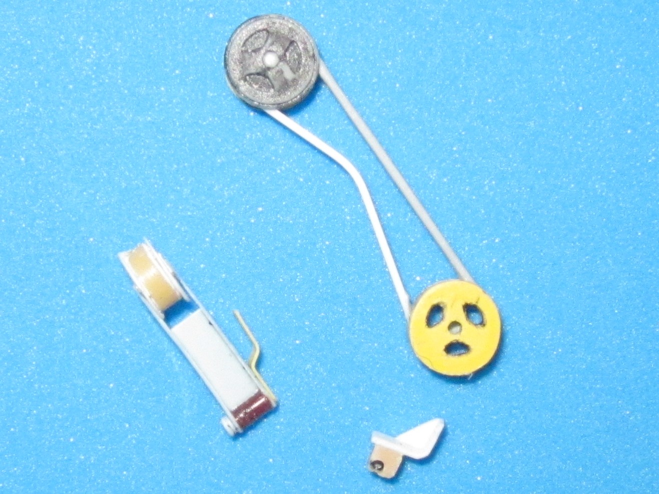
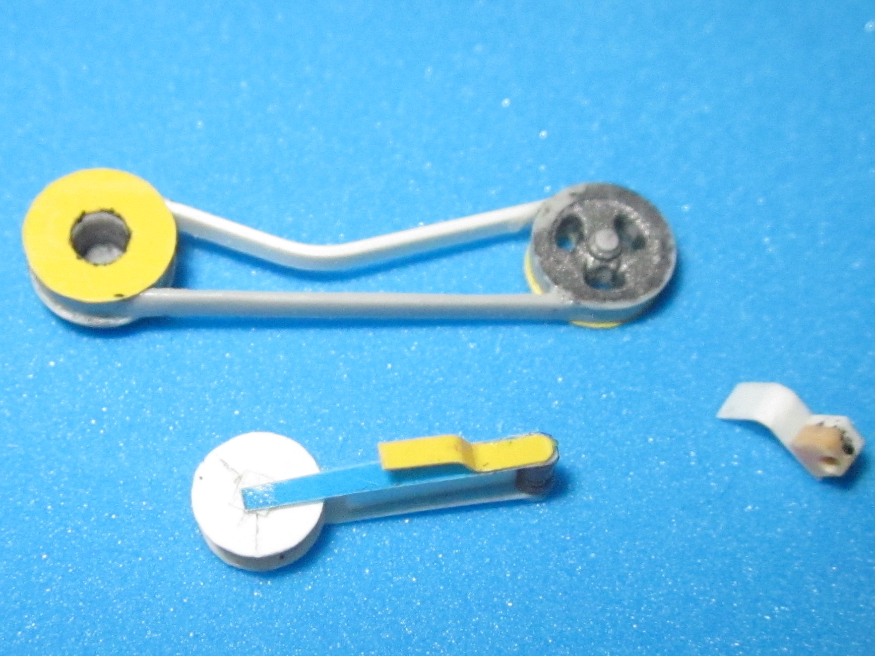
Arm and pulley were scratchbuilt together with the necessary tightener bracket, and the lower run of fan drive belt B40 had to be replaced by plastic strip with a “kink”.
Fan Drive Assembly B7 was wrong in that it not only was too thin but also unable to house bevel gear wheels in its round bend, so it was replaced by 2.5mm plastic tube.
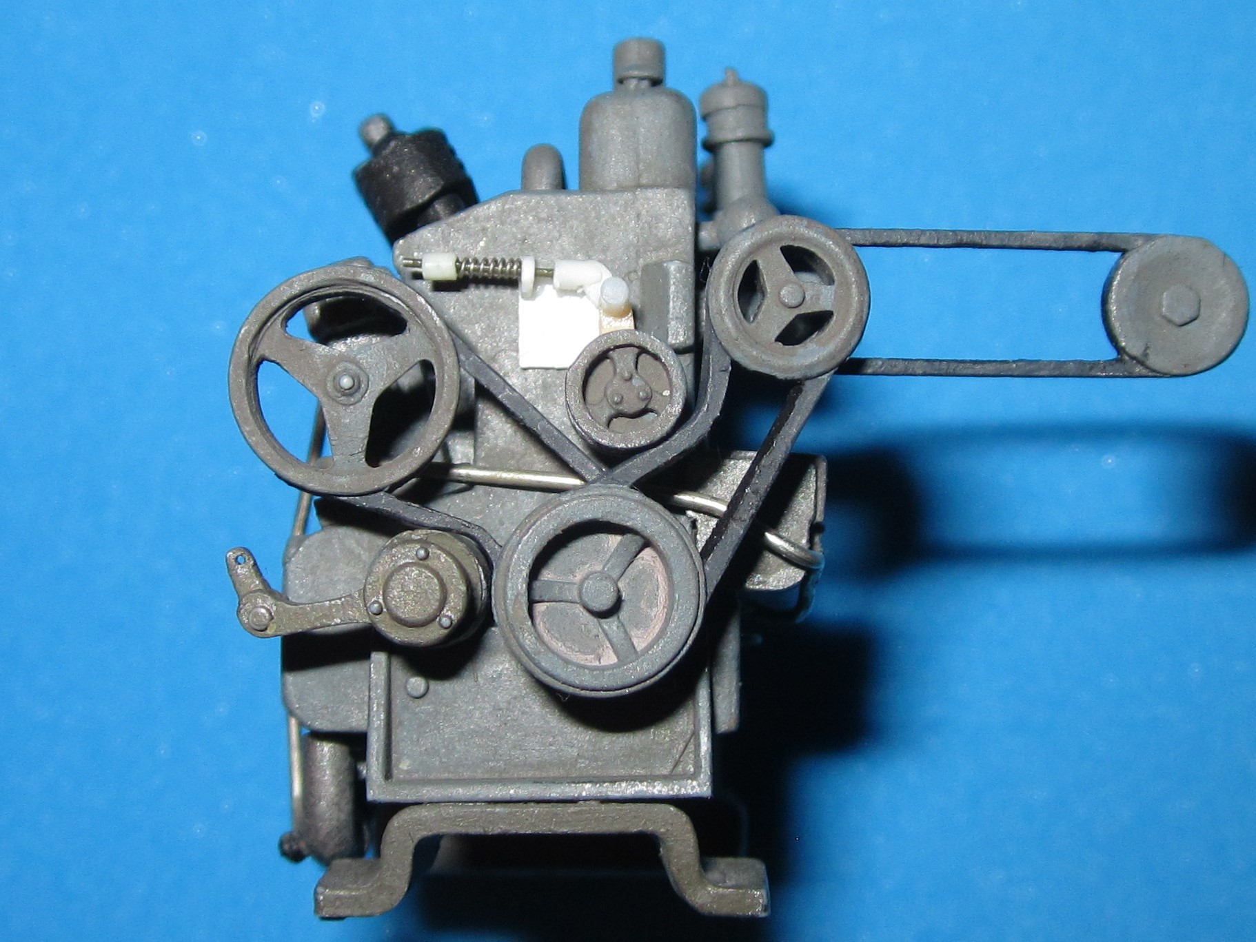
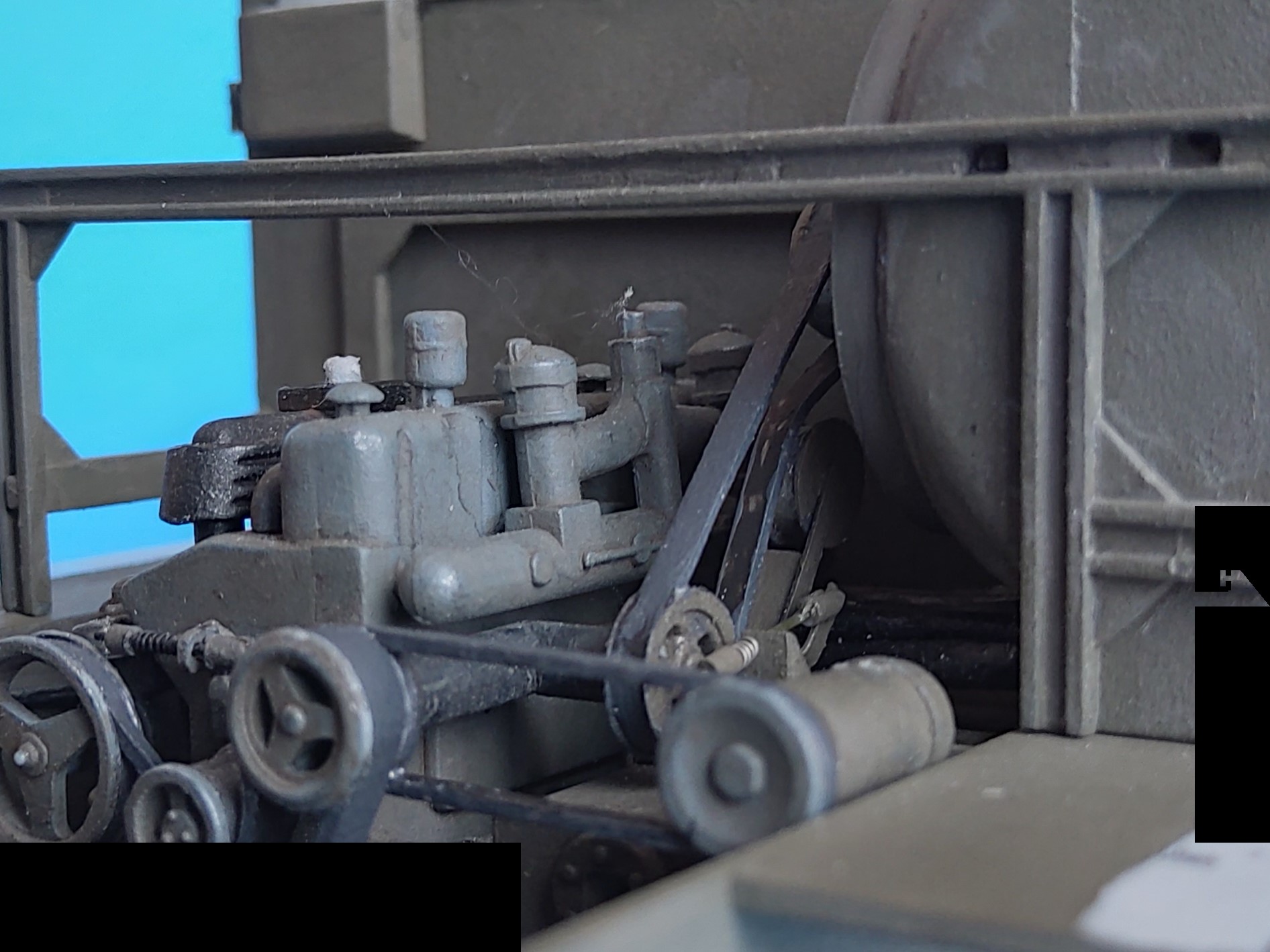
This has been a productive day:
The motor has had some wires and “hoses” added, and I built the mechanism for belt tightener pulley B49, which includes the pulley arm and its axle on a small platform. At lower left, part B19 is another tightening pulley, with arm, the adjusting mechanism to be added later.
And with the engine installed, the central water hose (extension of part B29, from solder wire) could be installed, together with the fan drive belt and its accessories:
Hi Peter… I’m impressed with all the scratch building you are doing to this kit.
I have both versions in my stash and an old Nitto kit that I did a lot scratch building on it a long time ago. I was going to hook it up to a Flack 88 that I have. I saw this combo in a WW2 picture. I still have them in my show case.
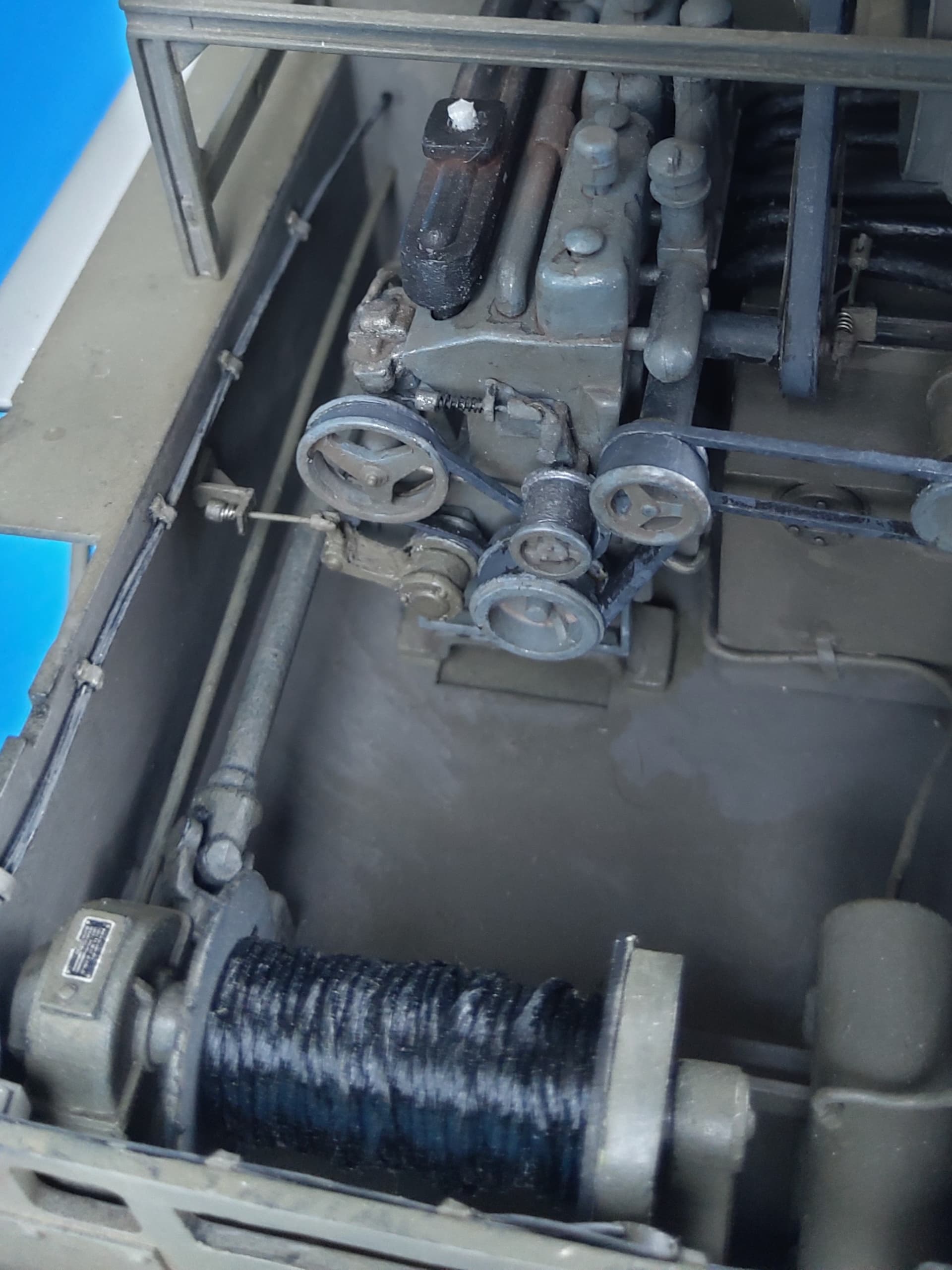
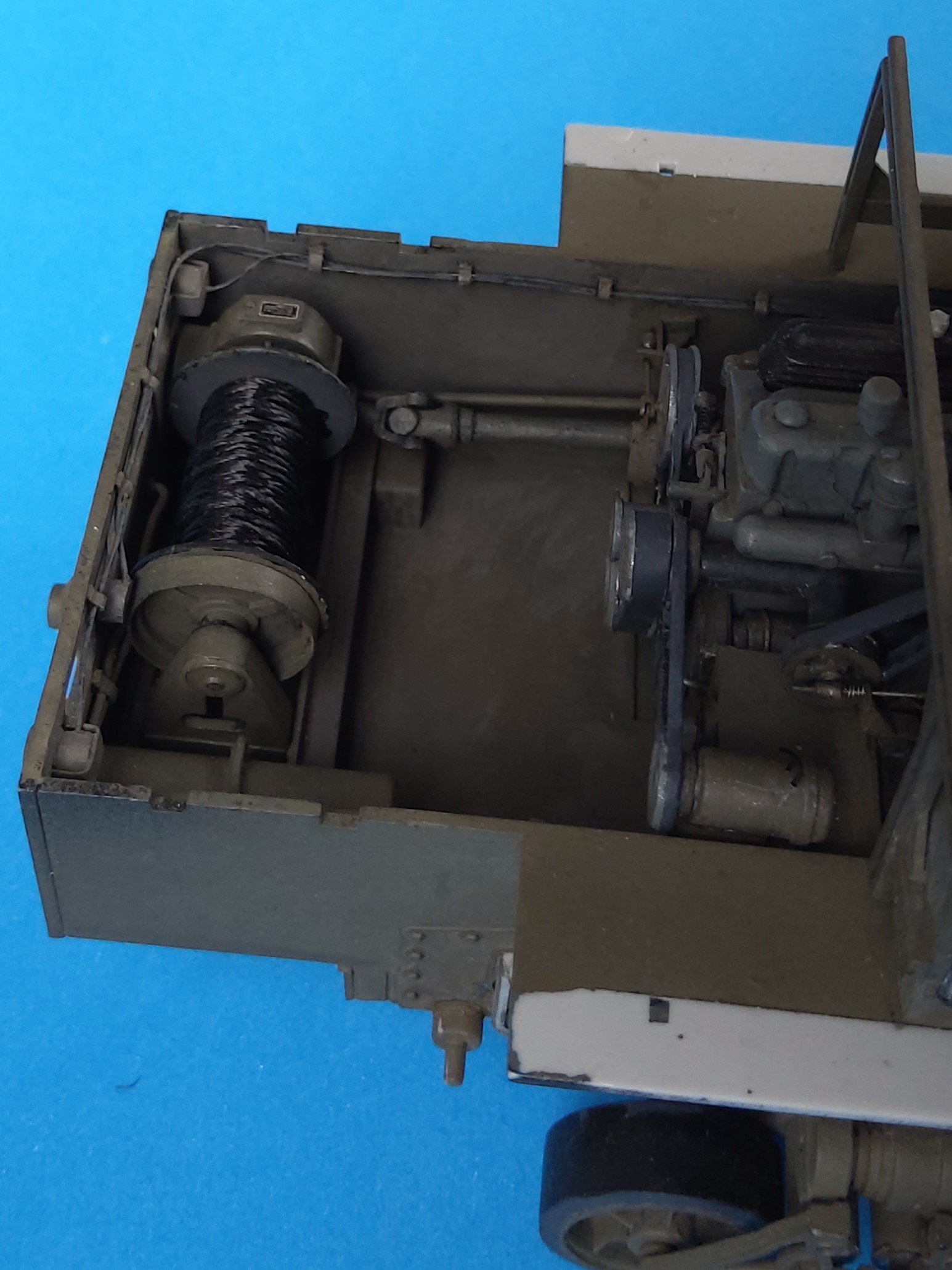
Here’s the winch drive housing. It received an angular top with type plate added and an “automatic brake housing” facing the rear wall. The winch clutch operating rod from 1mm plastic rod was mounted as best I could guess and its other end led into the firewall next to the winch drive shaft.
The winch drum received a 2mm wide plastic strip wrapped around its end opposite the drive and was wrapped with strong black thread instead of HB’s white nylon hawser.
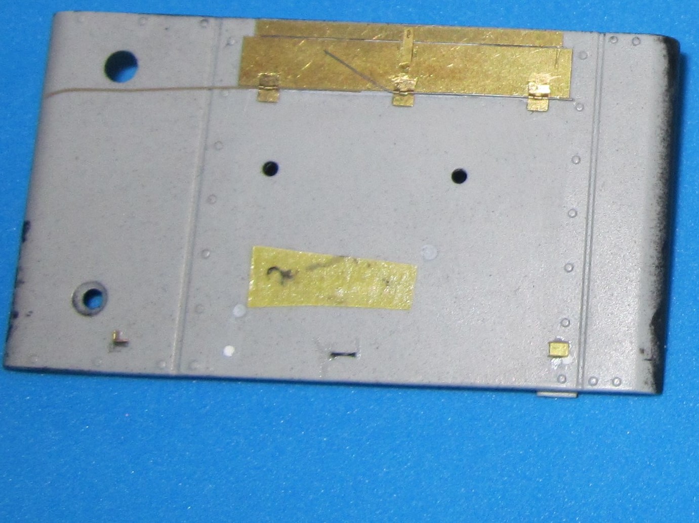
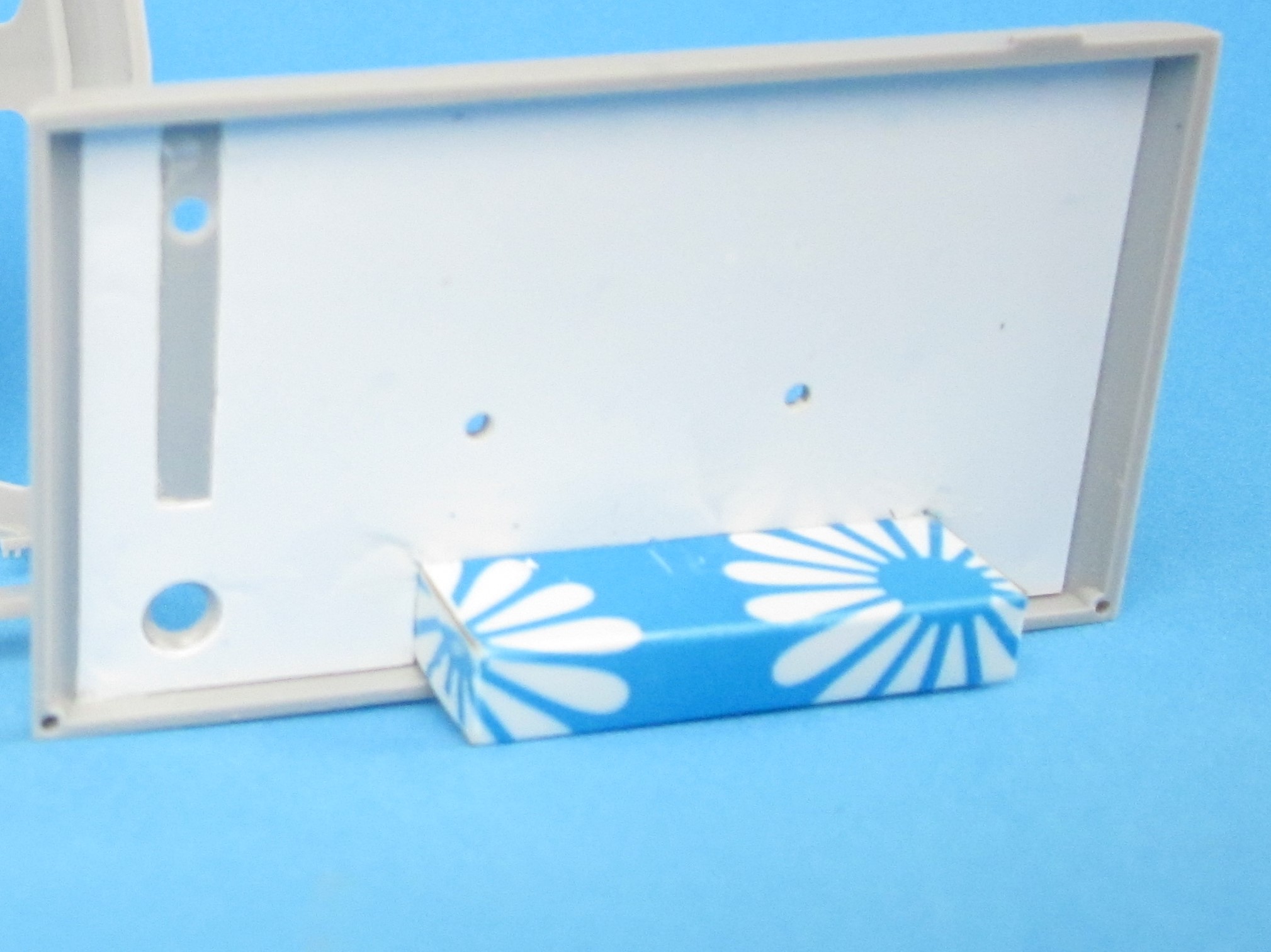
Now for the engine room roof. PART gives a lid with operable hinges for the rear part of B47. Which is no good without a hole underneath it, which would also give a reason for the existence of box C37 to be mounted there. References showed that that lid covers a “Box for Water Cans”, so I decided to cut a hole. Test fitting an Italeri can proved that it wouldn’t fit into C37, so I scratchbuilt that contraption from thin styrene sheet, again covering unused positioning holes with thin sheet.
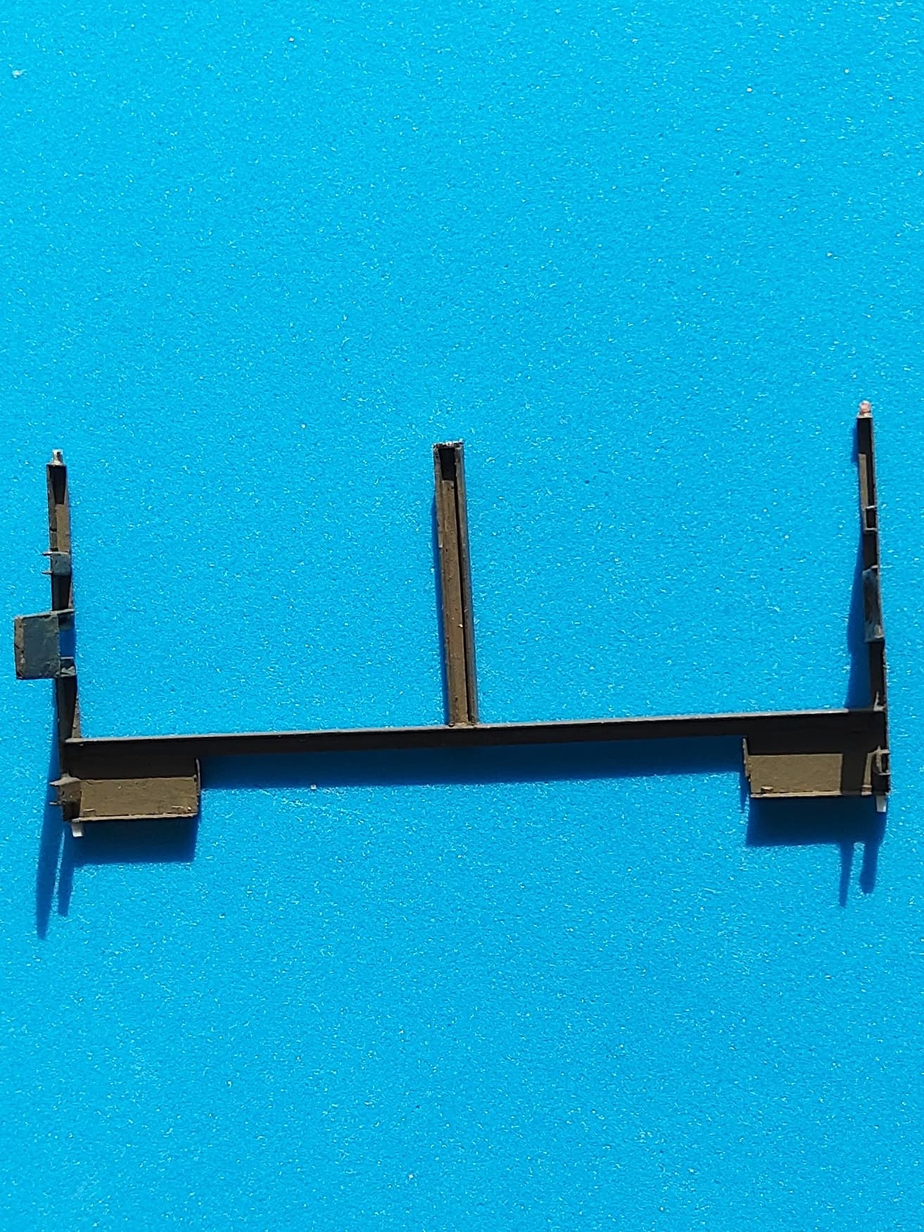
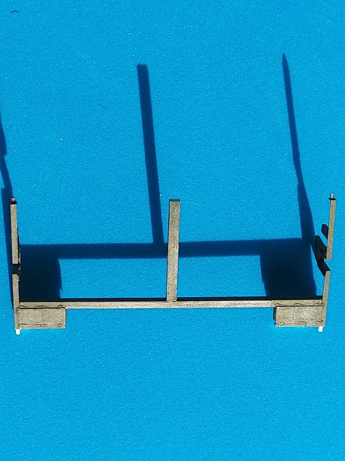
The kit’s roof supports C43,47 were extremely detail-free, so I turned to PART’s replacements. Scary. Those two “wedges” near the center are to be mounted standing to the right and left of the wide part. Not being the Great Solderer in the first place, I didn’t dare gaining further experience working on these, so I superglued. The two smaller additions with holes in them were positioned after prototype photos instead of in PART’s grooves. To achieve some more stability, I later filled a few of the cavities with Green Stuff. Little plastic pegs were superglued to top and bottom to go into the positioning holes in roof and fenders.
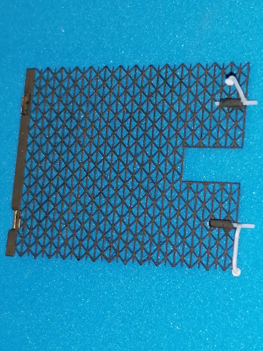
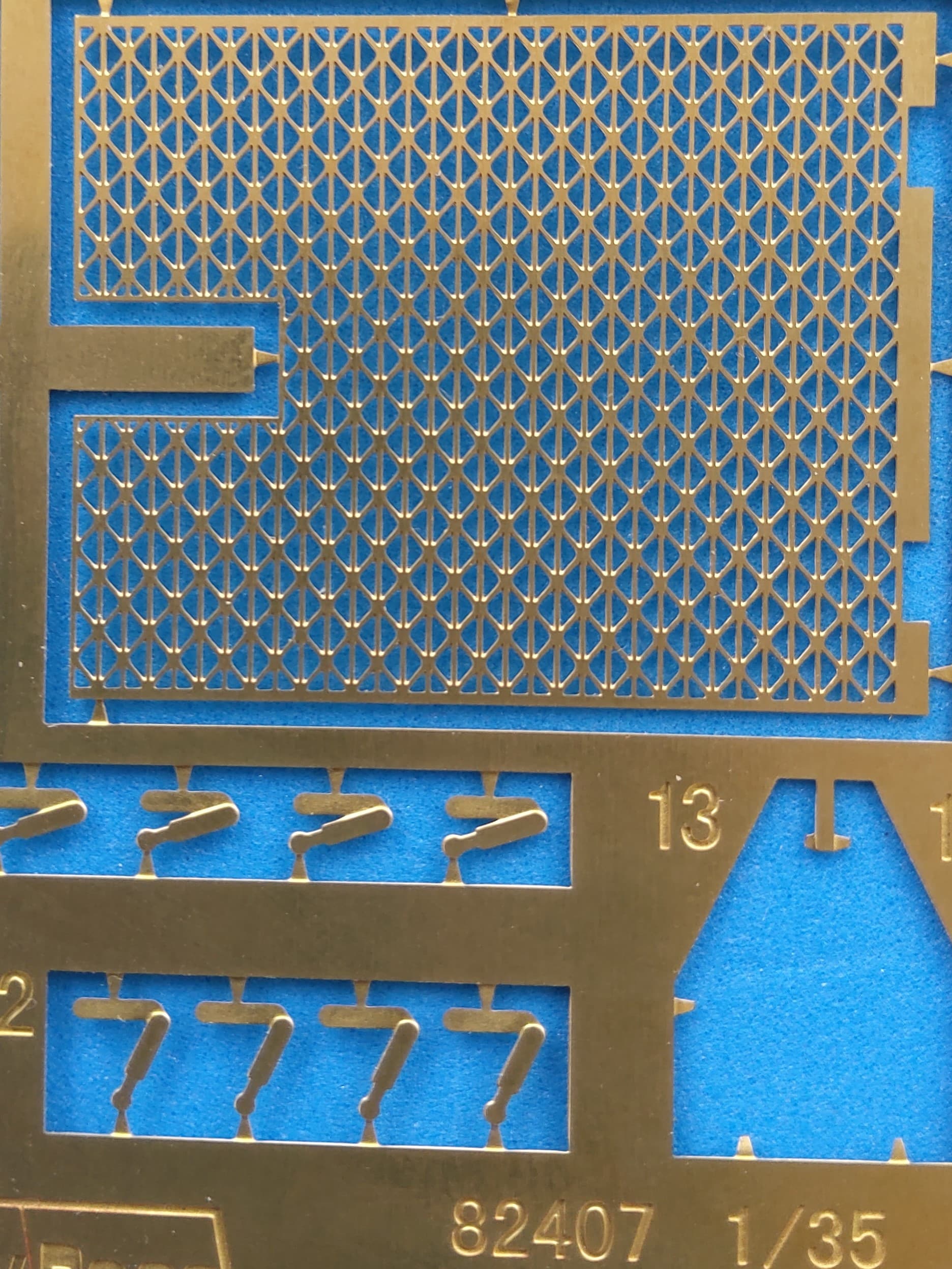
Before mounting the remaining engine room details and running the risk of knocking them off, I looked at the lateral grills. Comparing the PART offerings to what HB gives shows that the former not only are etched much more three-dimensional but also more correct in that they don’t have horizontal bars at top and bottom. On top of that, the PART grills are to be mounted movably!
(Note the identical shape of the HB windshield pushouts, as mentioned before.)
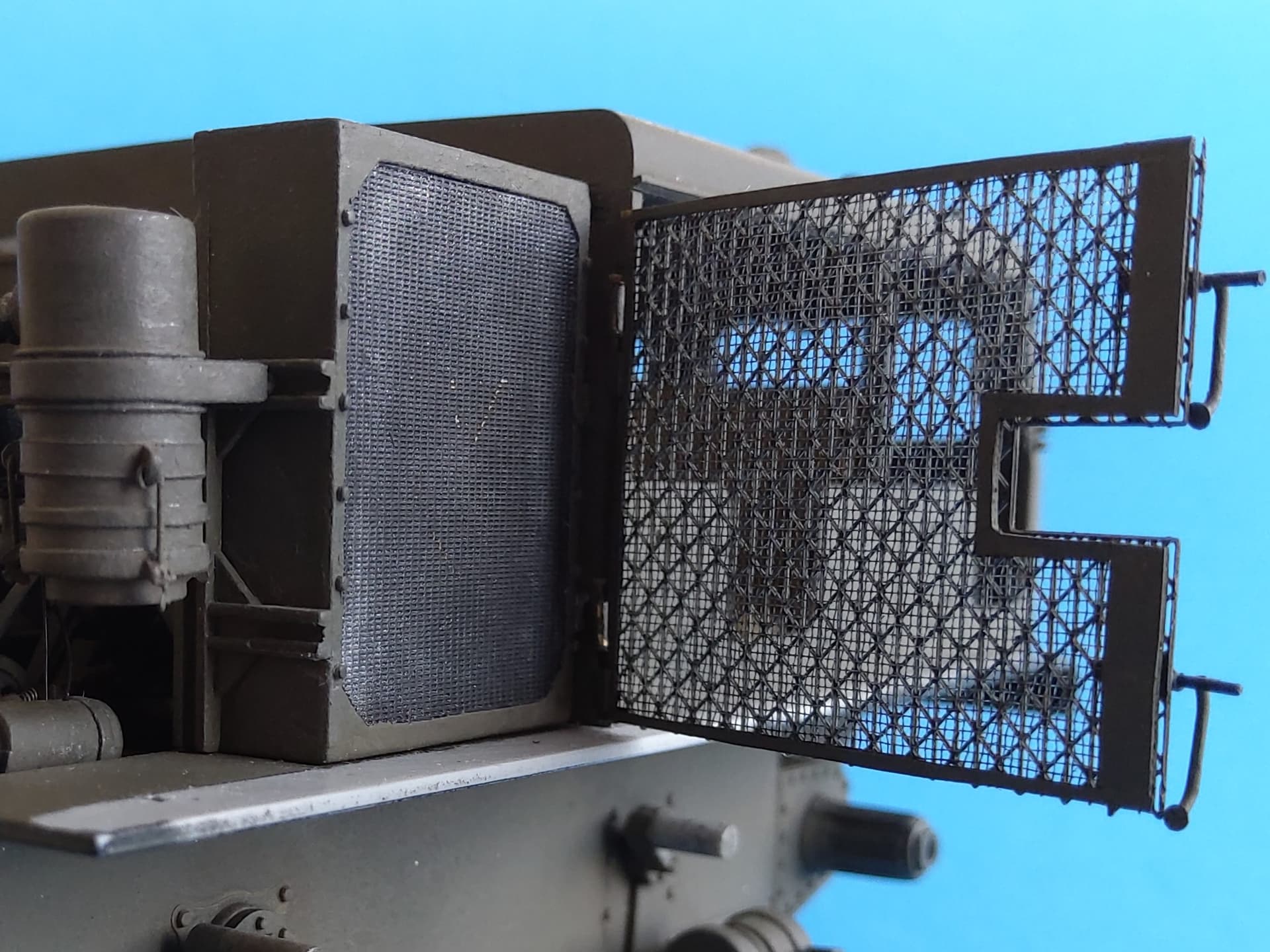
As also mentioned before, the PART set is for an “early” vehicle with grill locks similar to door handles, whereas I’m building a “late” version with bolt-like locks, so I scratchbuilt these: Pieces of stretched tubing with 1mm outer diameter were drilled out for 0.5mm rod to slide in them and more of that rod was bent and stuck on as handles, with punched out disks from thin sheet at the ends. “Gates” from short pieces of rod and plastic strip will go onto the posts.
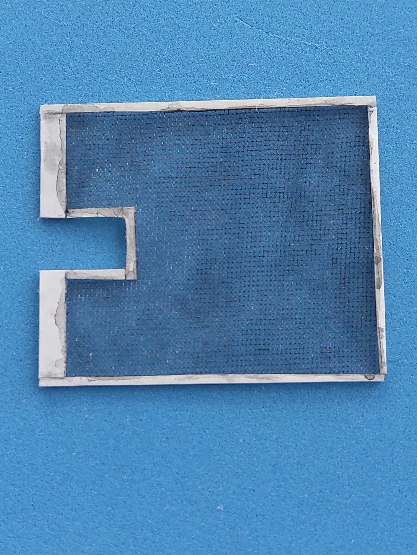
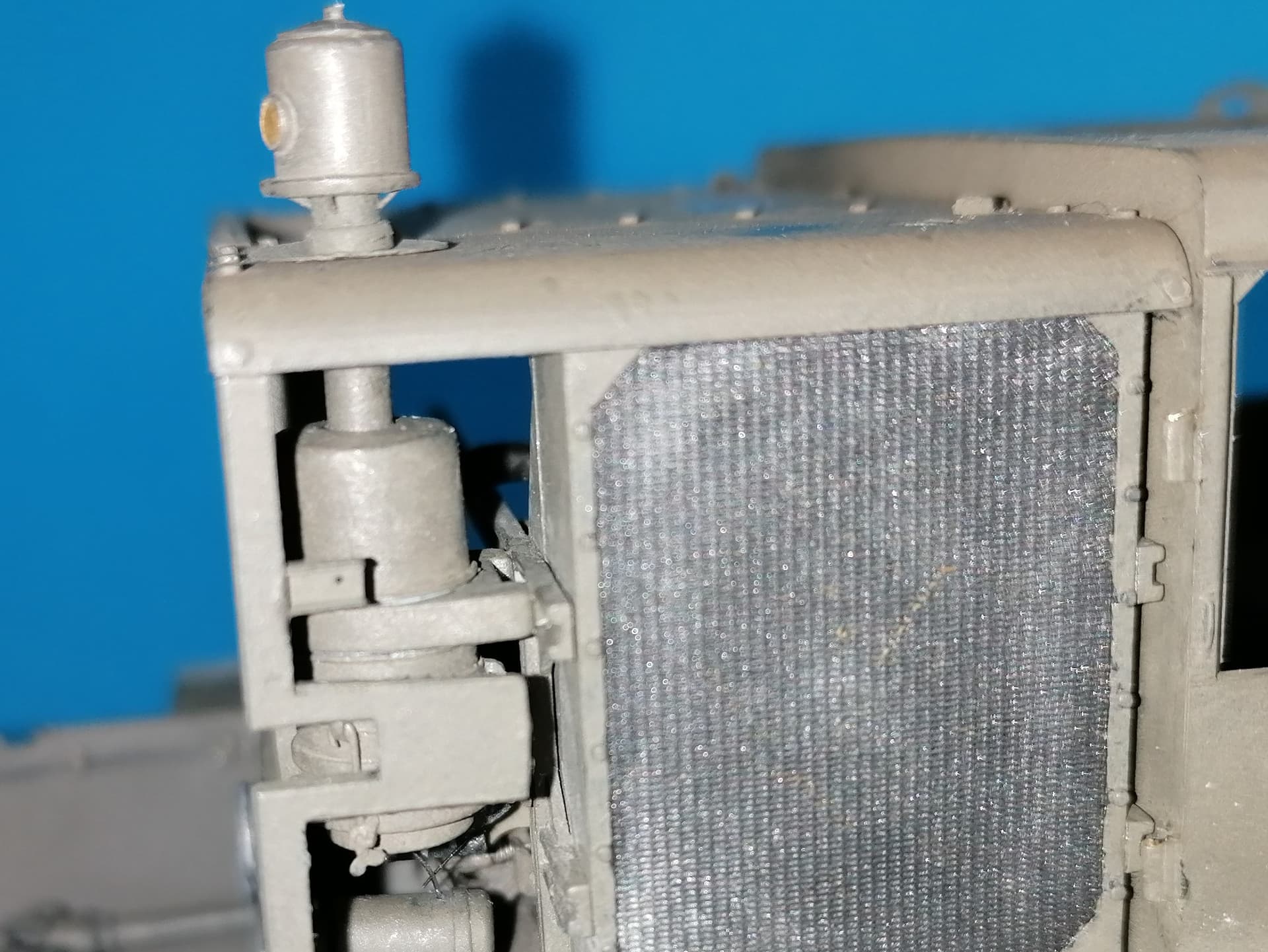
Research once again led to additional work, as I found that between the radiator face and the grill protecting it, there’s a very fine wire mesh, supposedly to keep out flying debris. This could be cobbled up from nylon mesh of unknown origin and a frame of Tamiya “Pla Paper”.
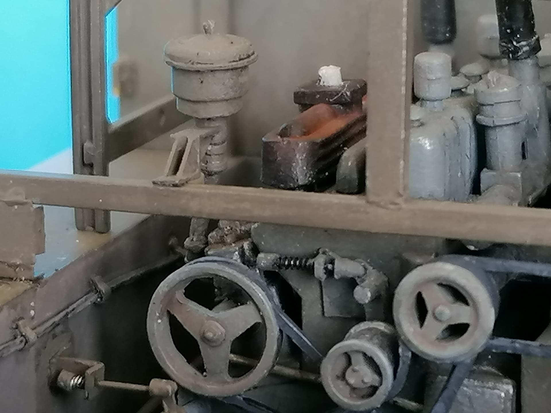
Continuing with the engine paraphernalia, the air filter received a second sheet strip and three fixing rods from wire with styrene mounting points and ABER wing nuts.
It consists of the two PE posts that are connected by 2mm Evergreen channel. This carries the upright channel that supports the roof. The lower parts of the posts received rectangles of thin plastic sheet that were “spot welded” on with superglue gel. Short pieces of square and round rod will go into the locating holes at top and bottom. - Nothing of this except two plasic posts is offered in the kit.
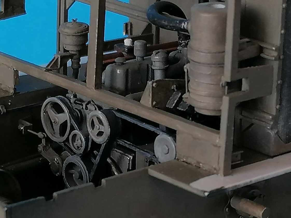
Completion of the engine room’s acoming nearer:
With the “frame” installed, the hose from the air filter to the engine could be cemented in, as could part C4, which I believe to be another filter, this time for the air compressor. I’ve given its support flange two triangular “fins” instead of the single one it had.
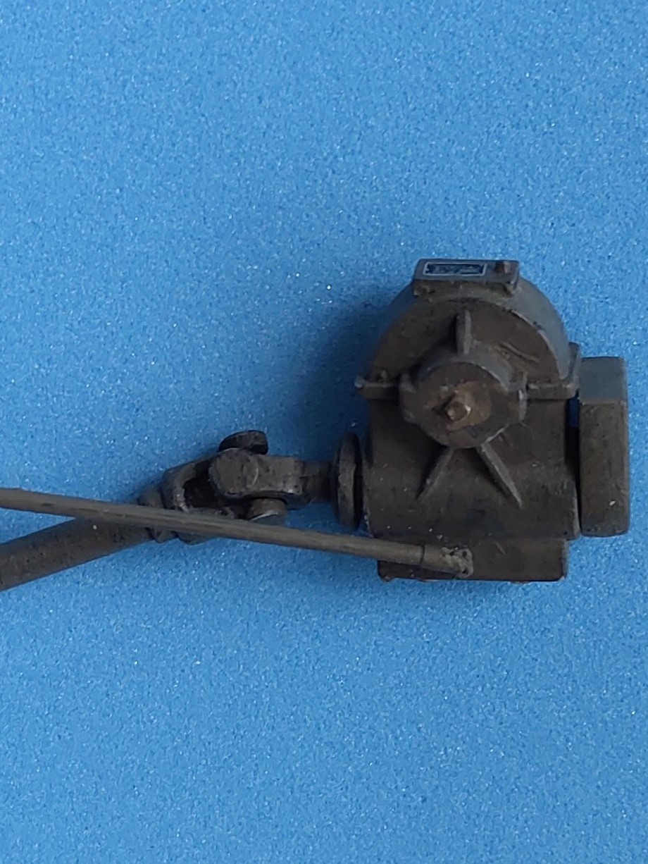
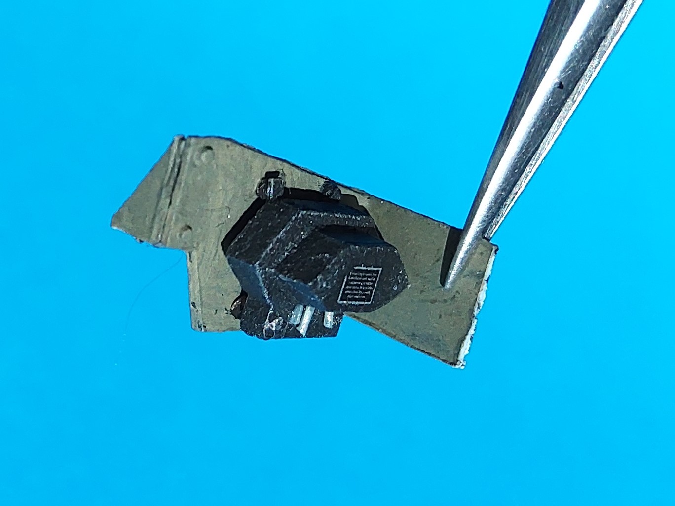
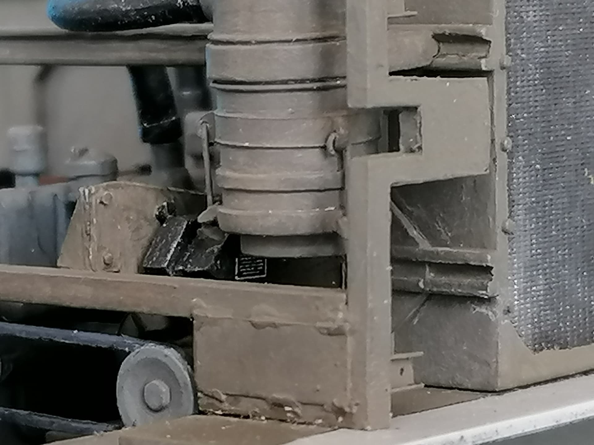
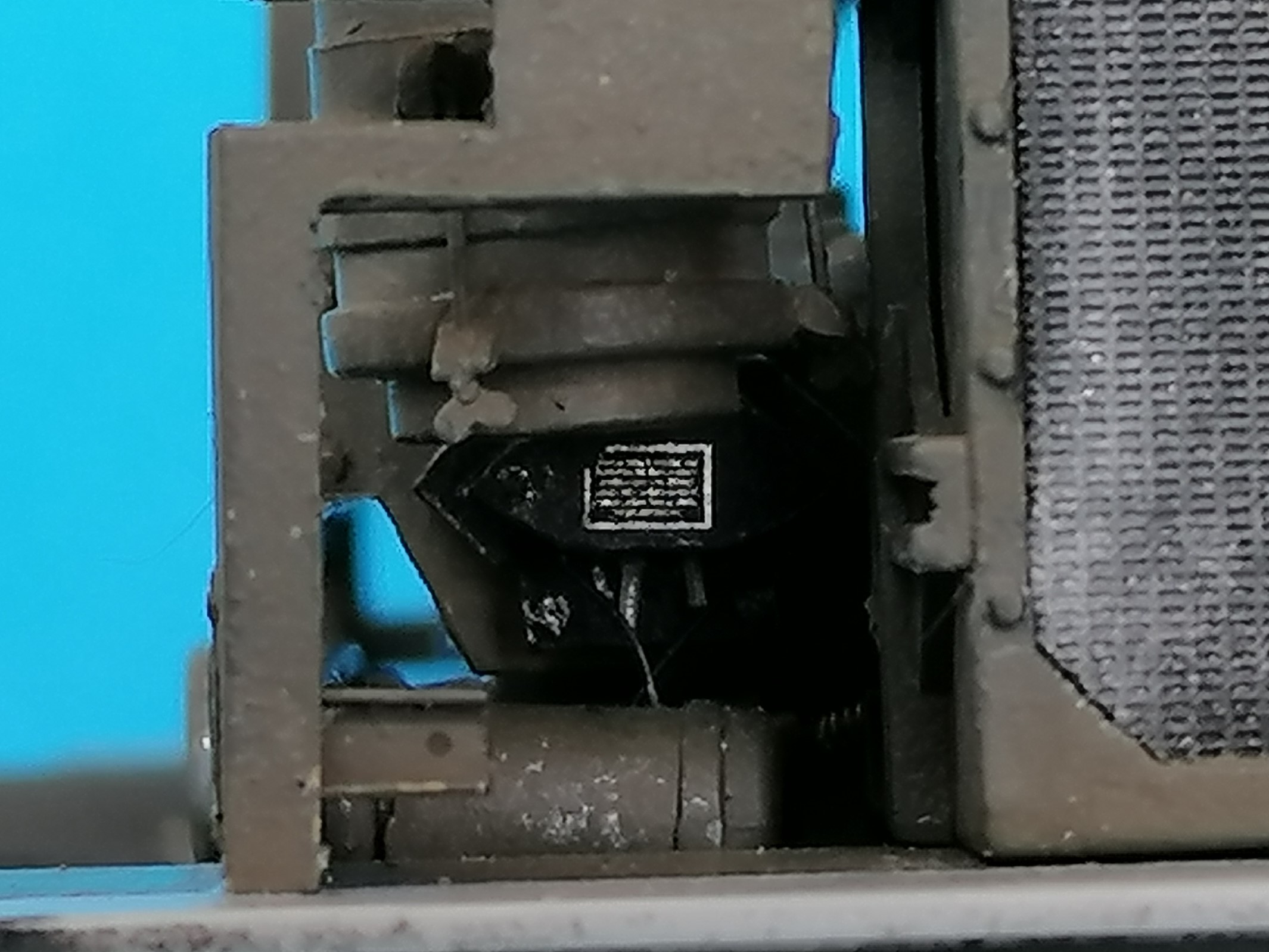
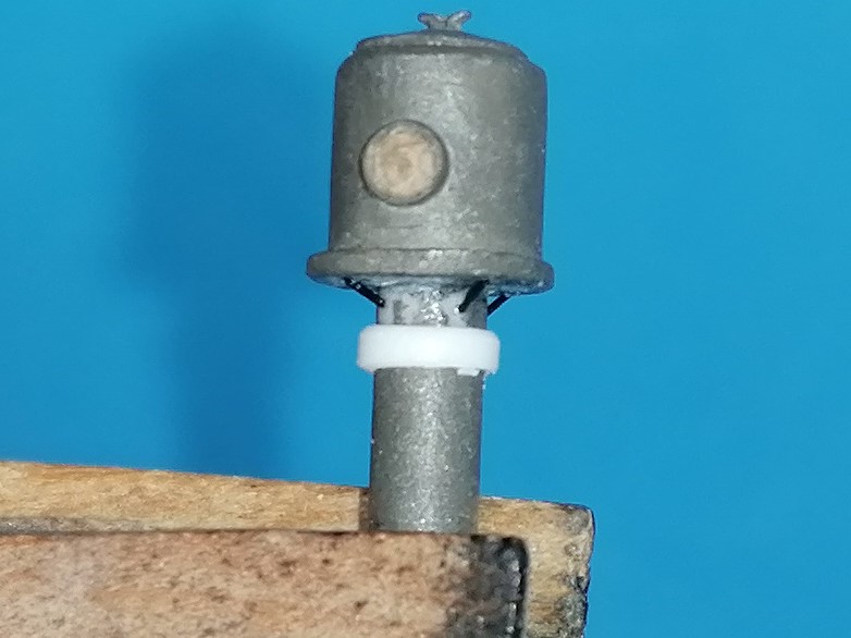
Another part that could now be added was the Voltage Regulator. How Kurt Laughlin and Frenchy helped me find out what that is can be seen in the thread “Hobby Boss M4HST engine room question”. Here’s my scratch build and where it went:
That the main Air Filter now isn’t perpendicular any more is due to my water can box going deeper than the kit one and having pressed on the hose - I’ll have to see what can be done there. But not today…
Peter
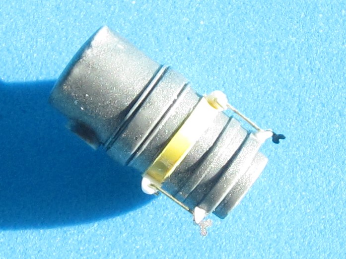
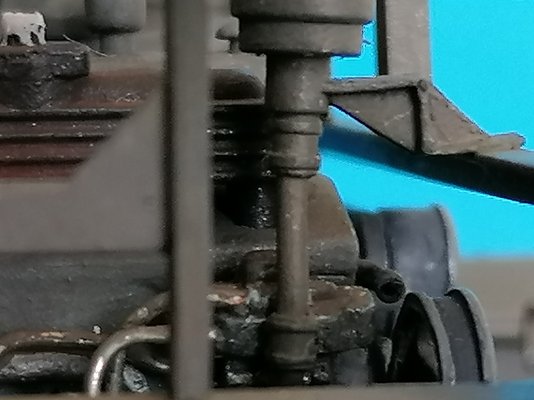
This brought the filter back to vertical, so it can now receive the Air Pre-Cleaner B6. Which needed some detail improvements, like replacing the oil check glass with an acetate sliver after drilling it out and painting the hole greenish-yellow. Unfortunately, this glass still sits too low on the housing, but relocating it was too much trouble even for my AMS. However, I added four tiny braces from stretched sprue and a ring around the filter tube. And a circular plate from PlaPaper around the tube on the roof will keep the rain out of the engine room.

 crazy. I love it! Keep it coming sir!