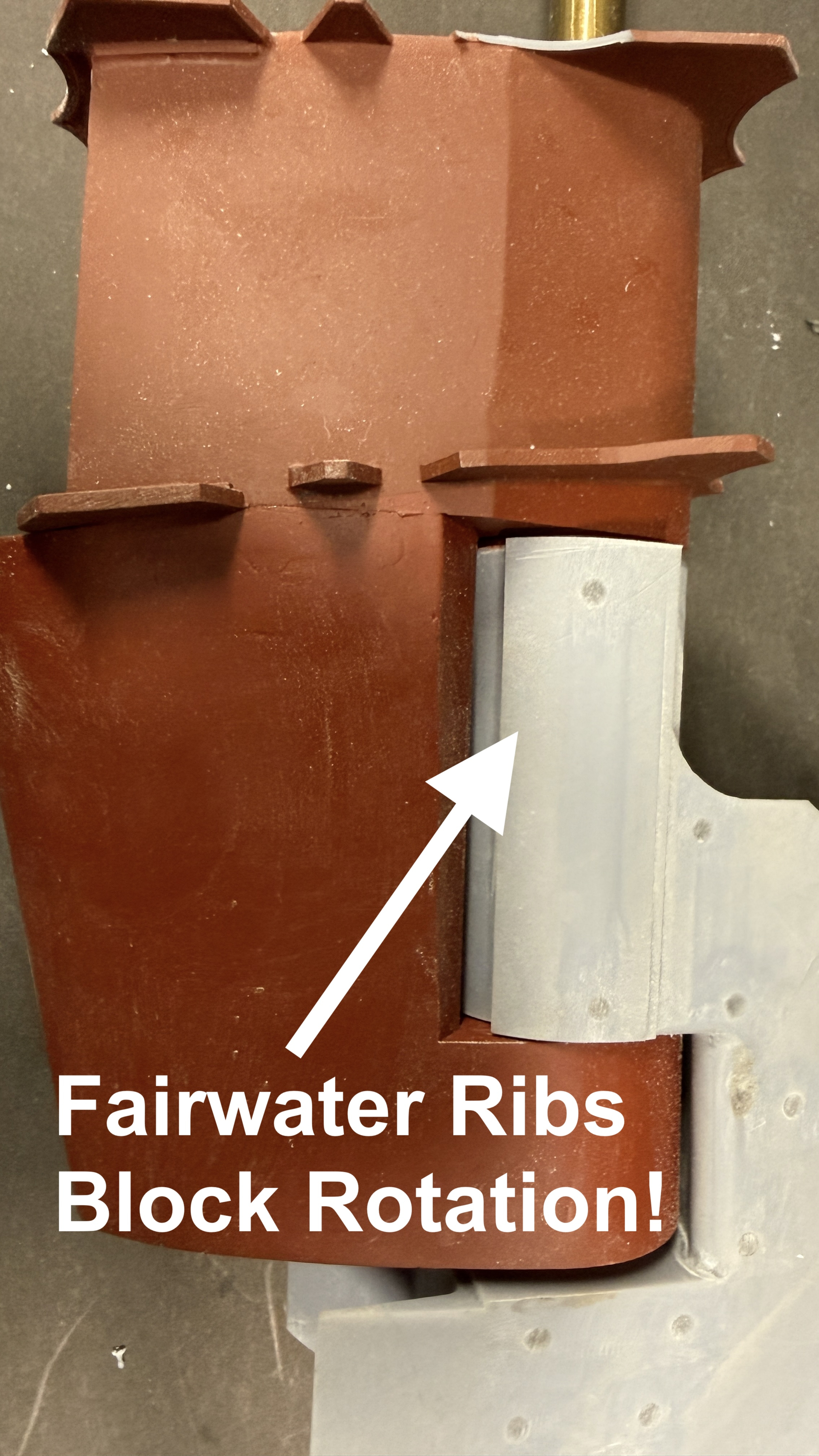
Iowa Class 1:48 Automated Steering Gear Model Start-to-Finish Build

Two steps forward, one step back…

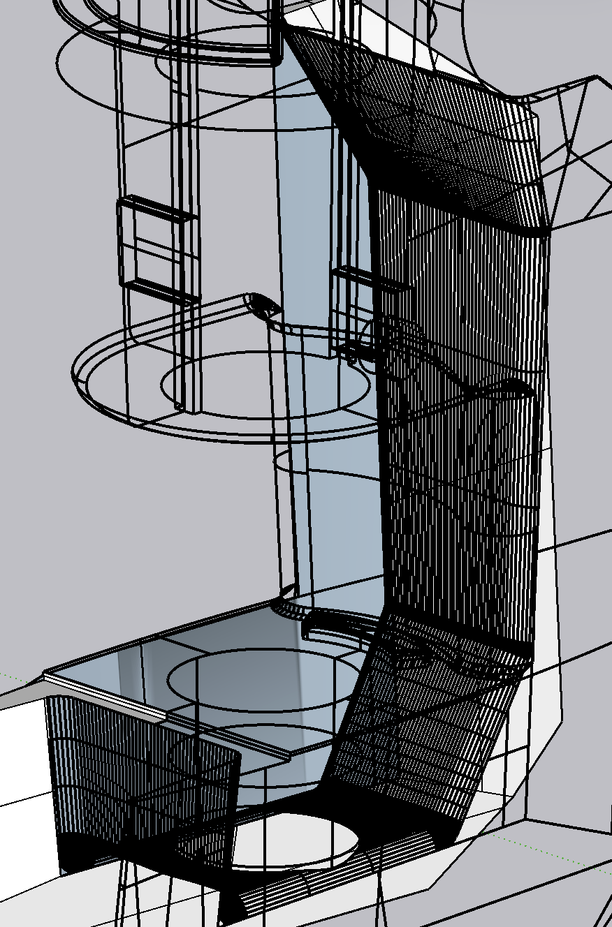
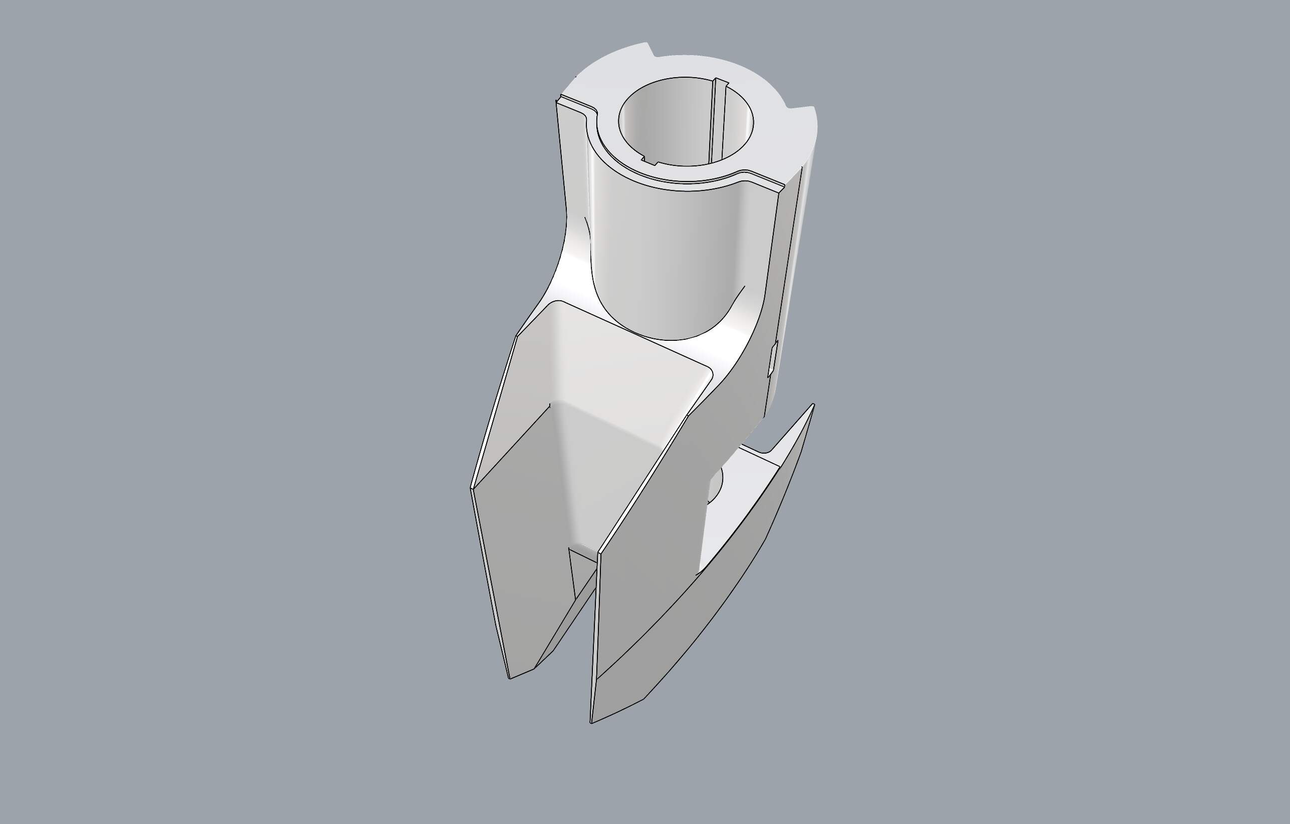
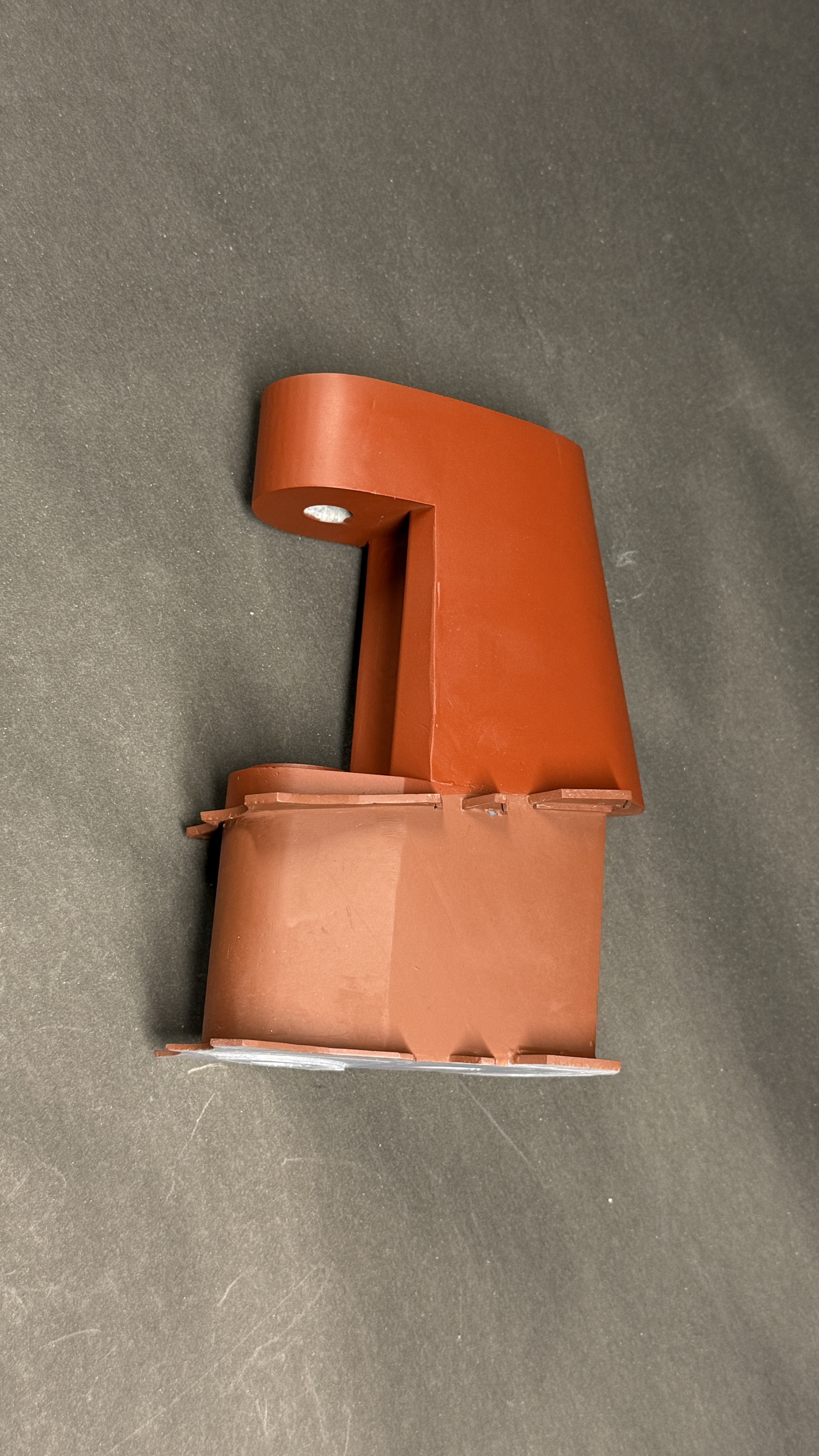
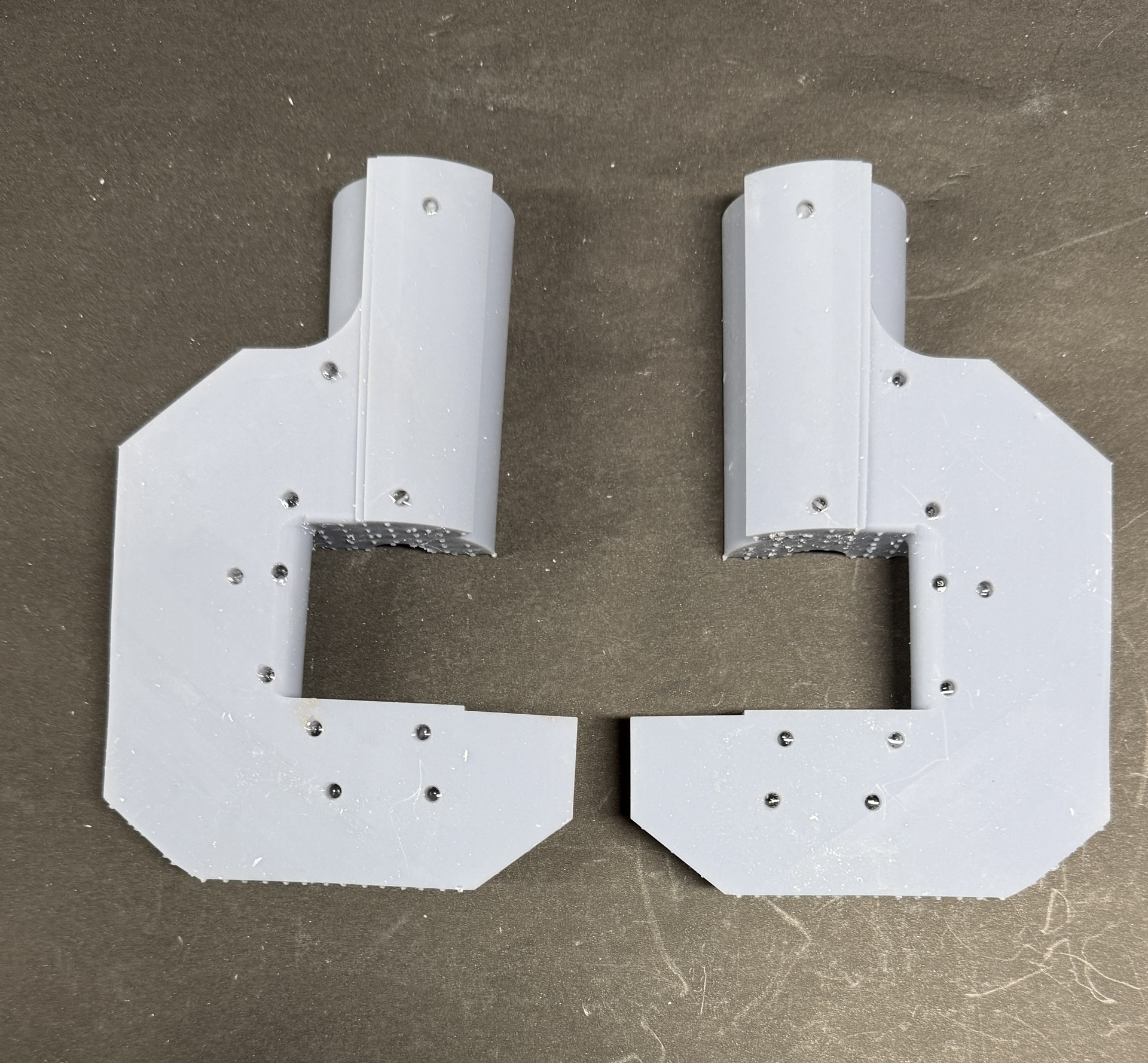
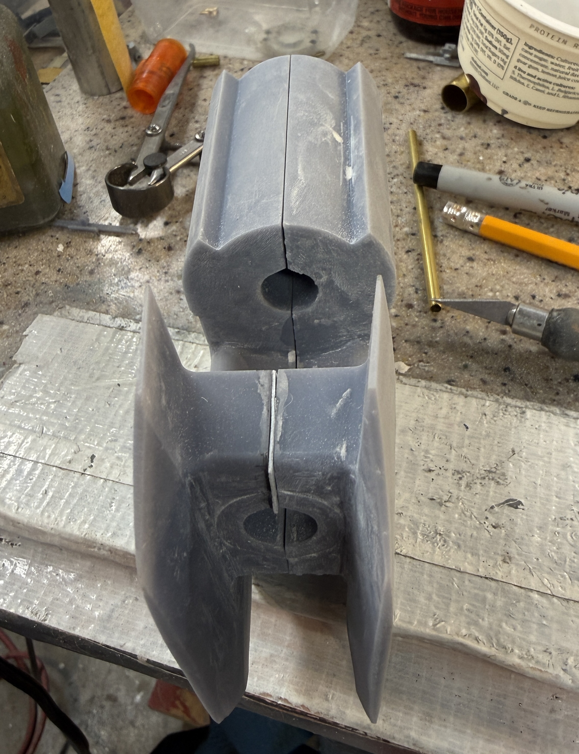
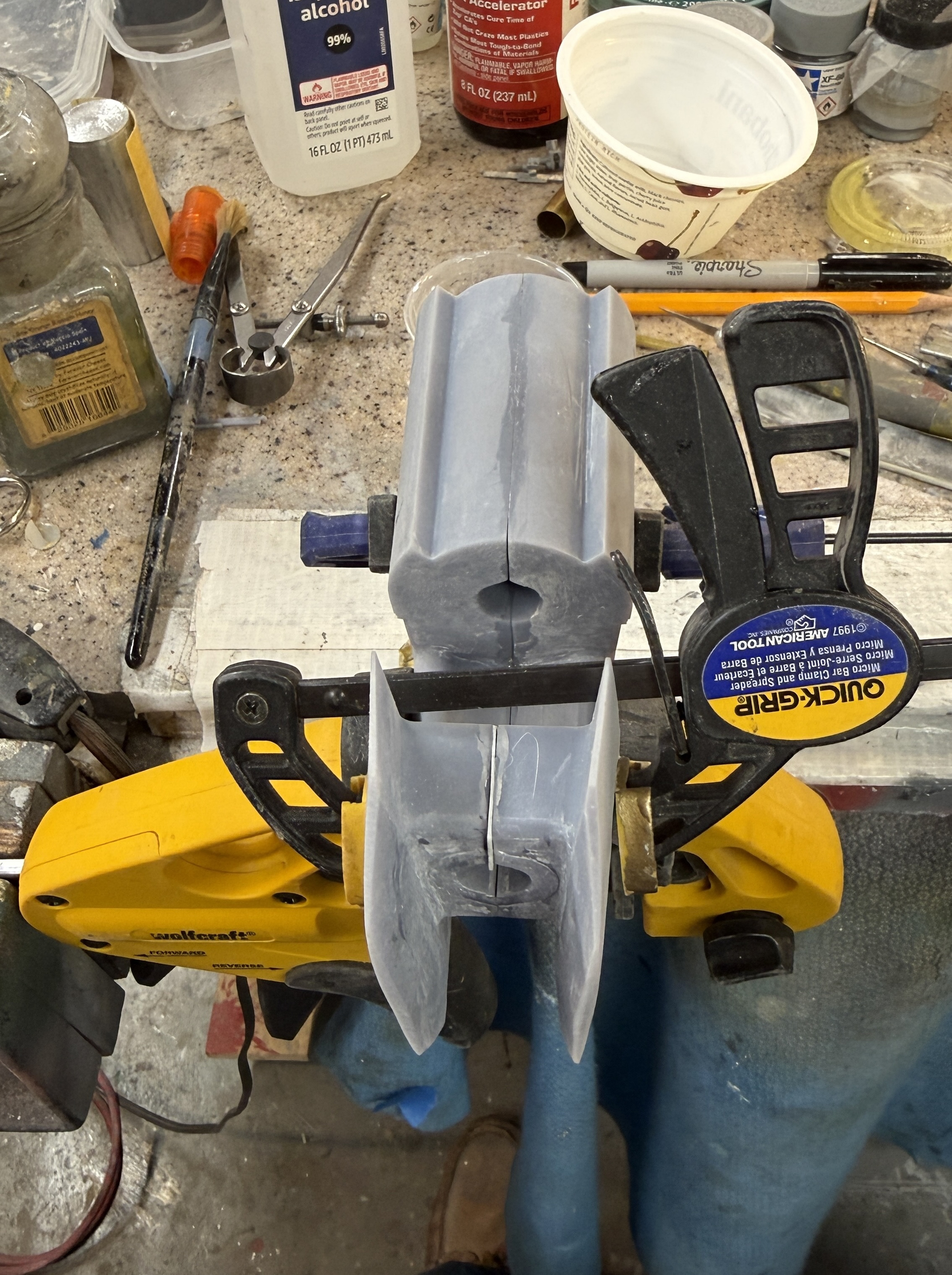
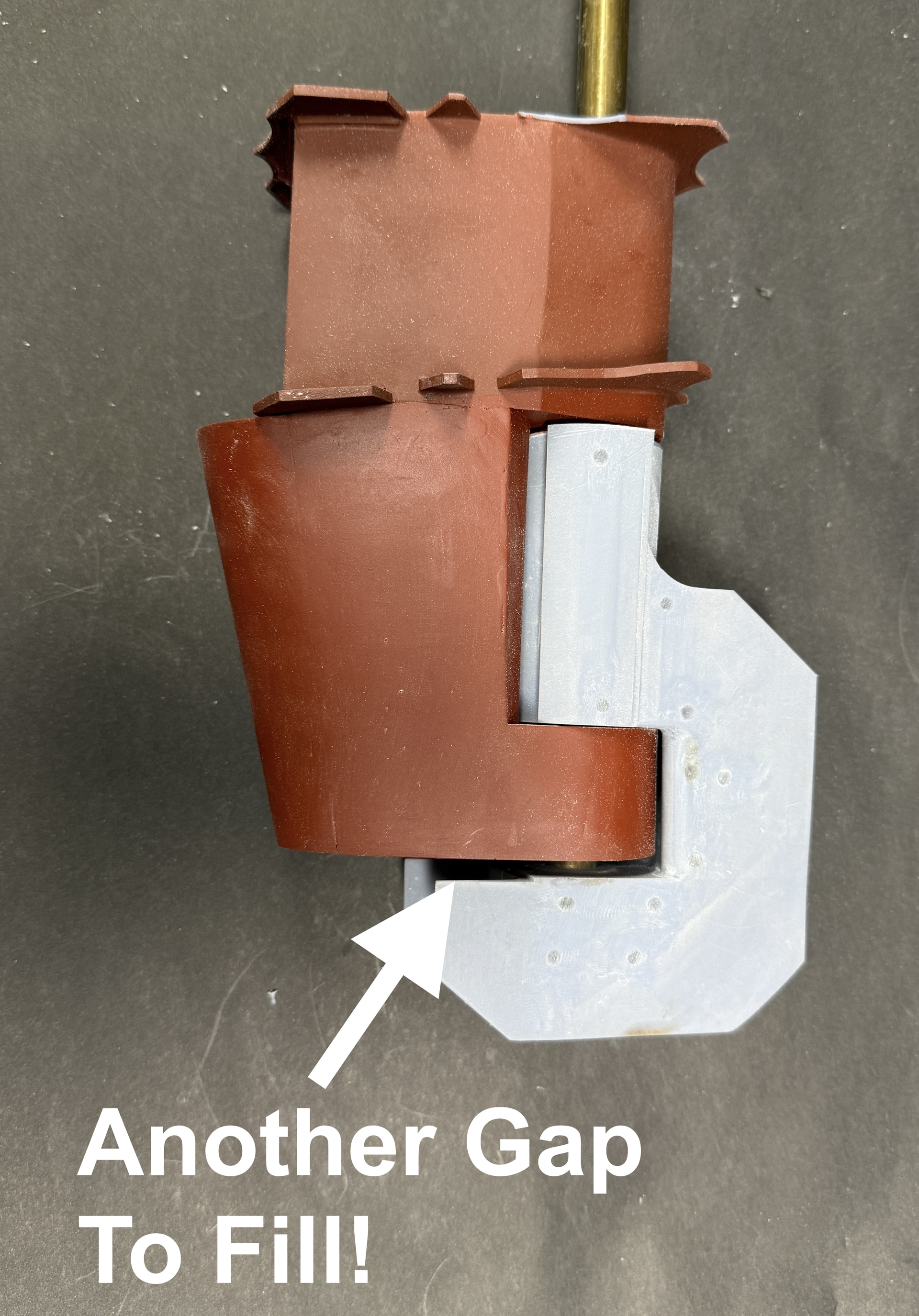
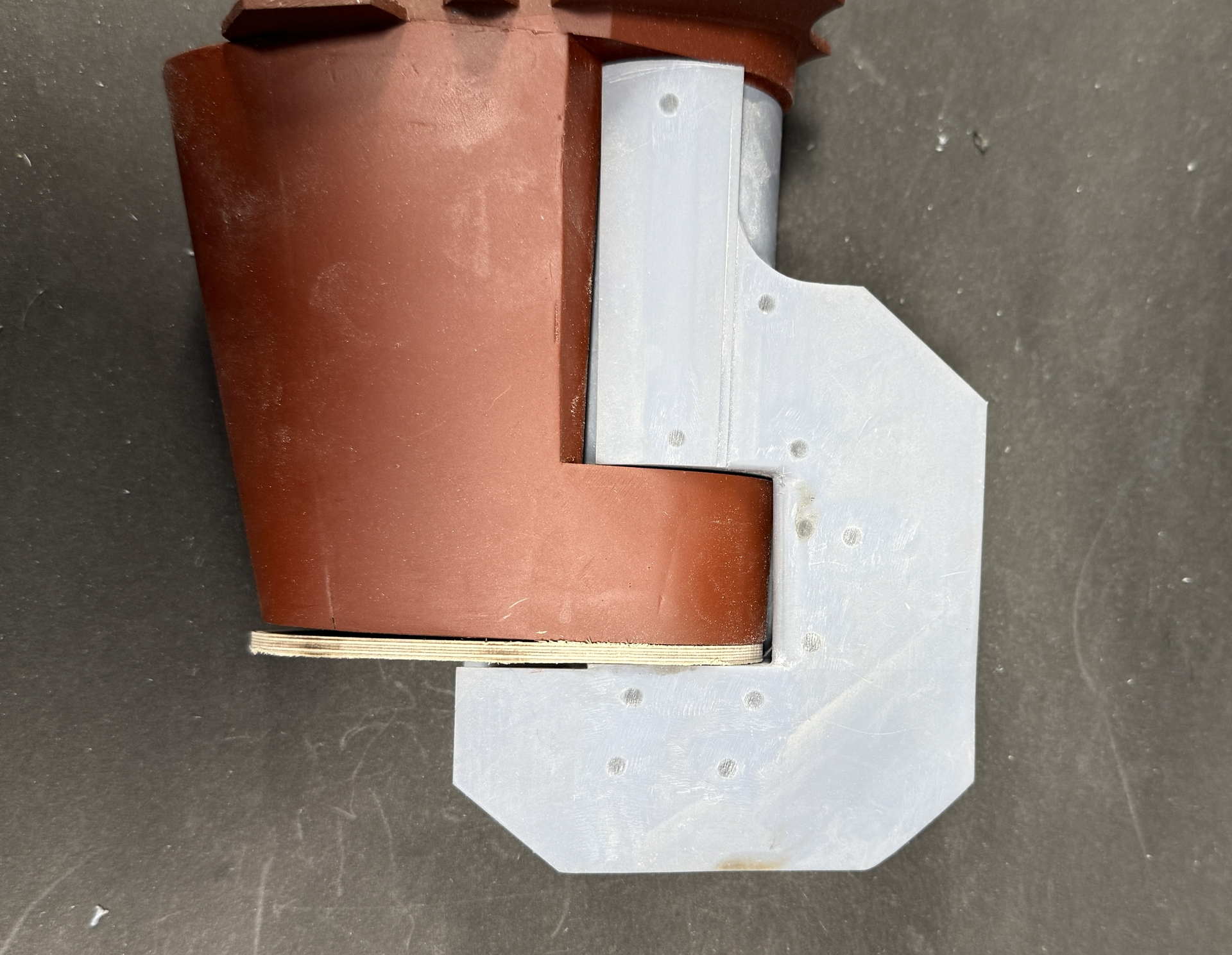
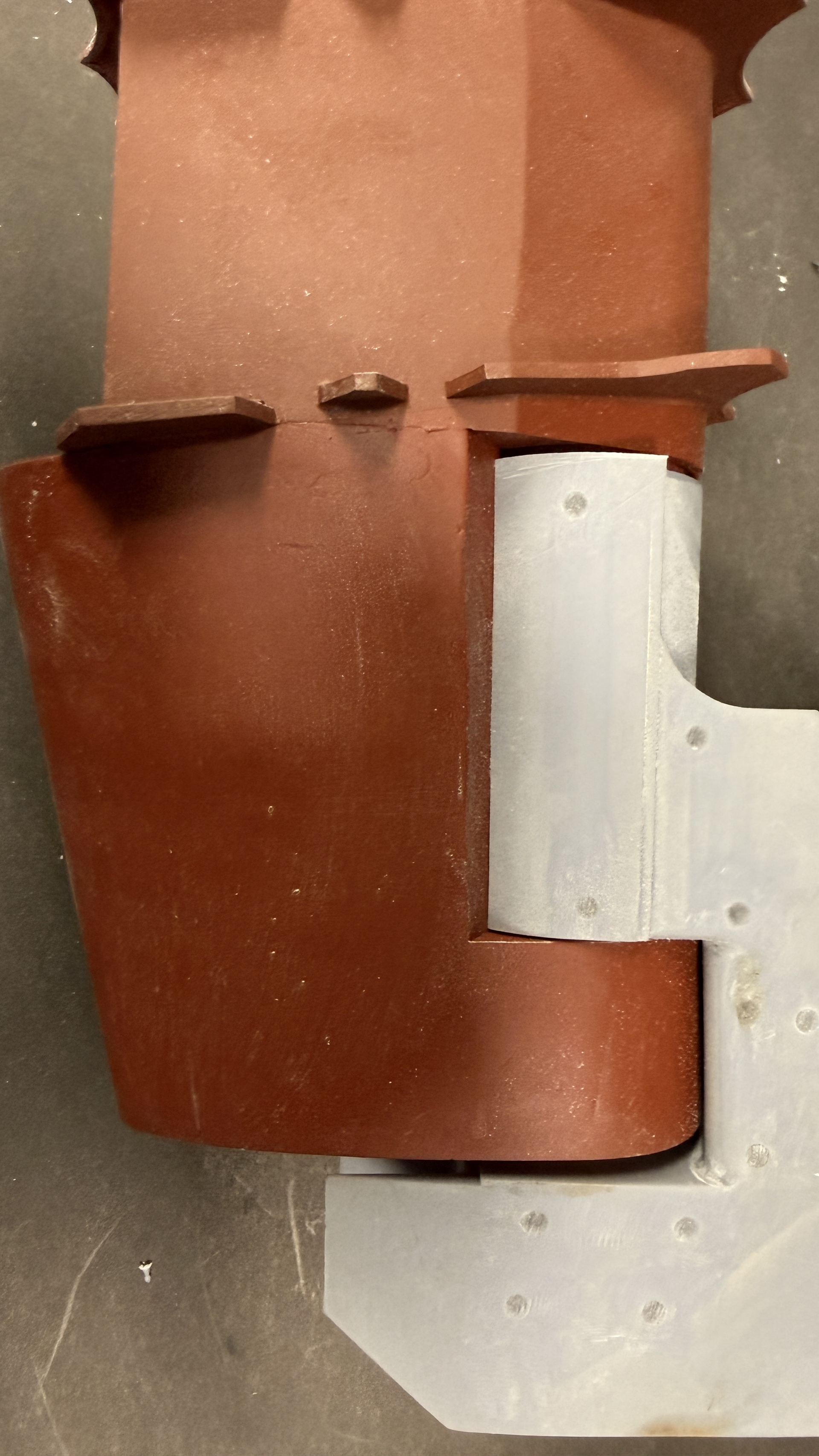
The repair of the first Rudder Hub print continues successfully. And I machined the center piece of the manufactured servo horn that’s going on the rudder stock. Those were the good things. My 4th and last attempt to print a new Rudder Hub failed miserably with almost a complete delamination of the base layers. I never had this problem before with this printer and I did print the repair sleeve and the top assembly for the rudder stock in between these failures.

Let’s see the good stuff first.

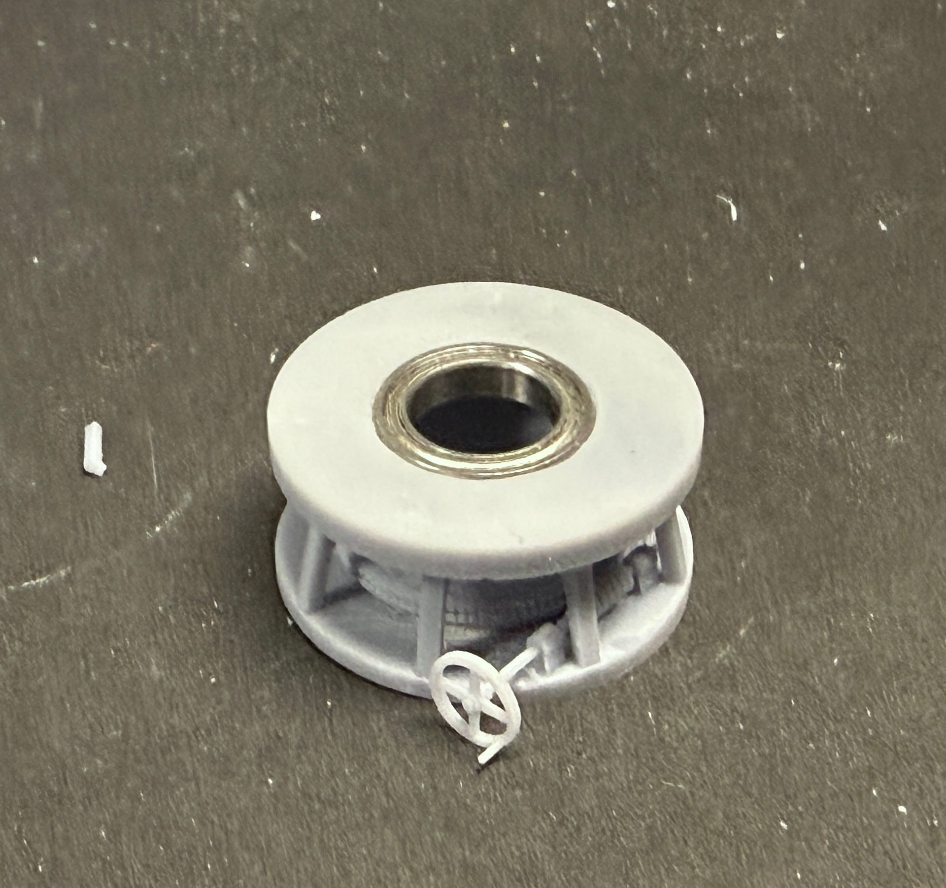
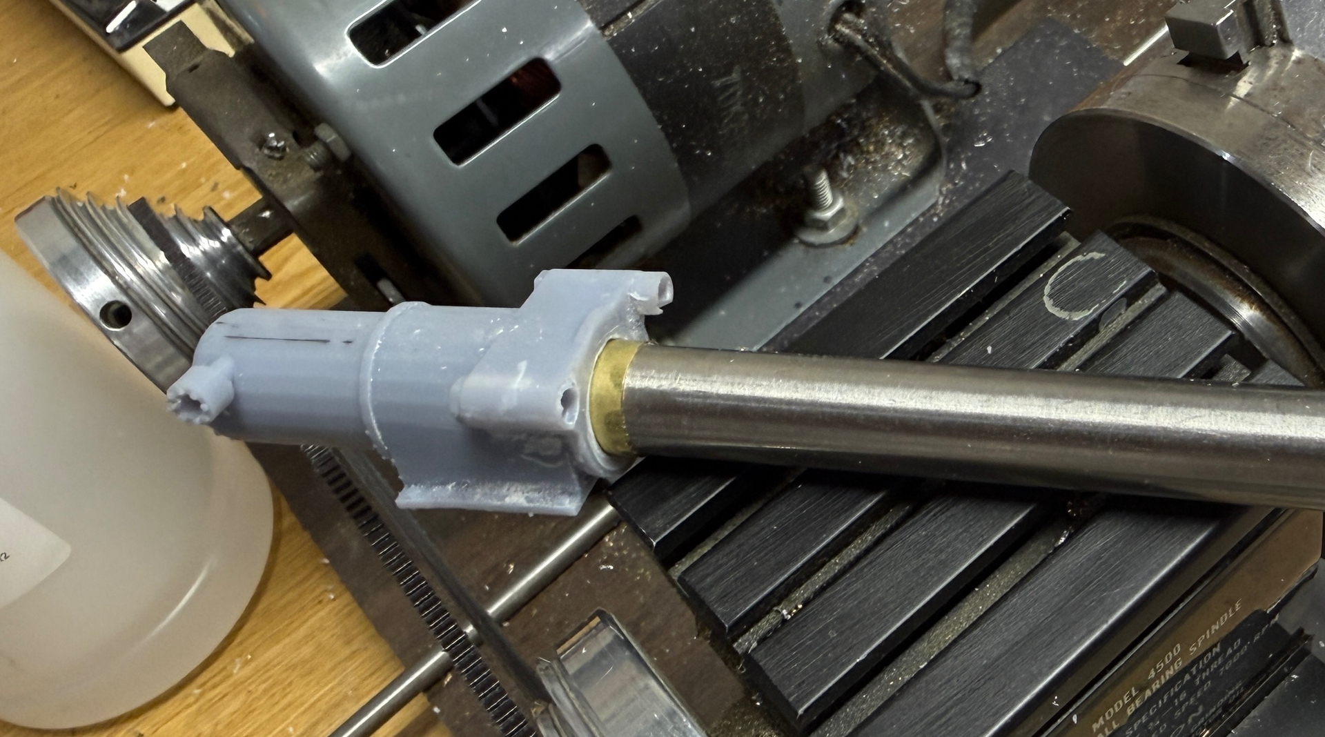
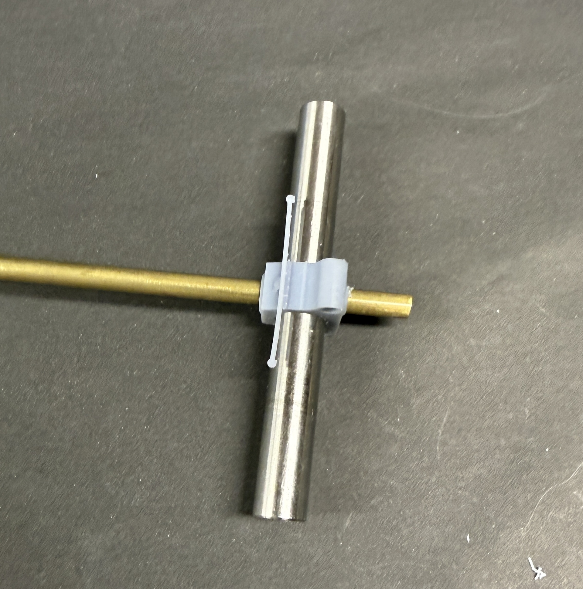
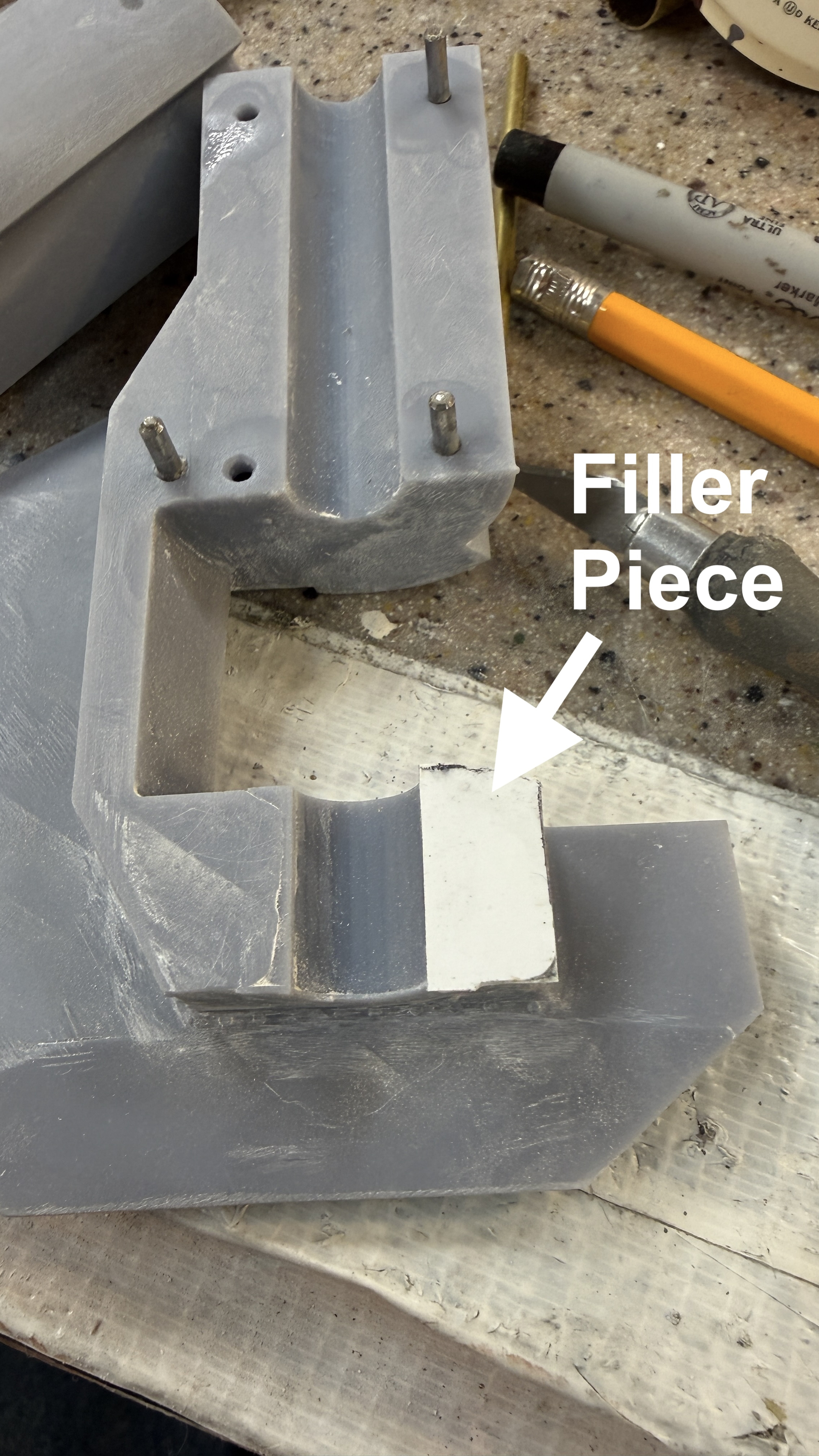
My sizing on the repair sleeve was dead on. It slide nicely onto the 1/2" brass rudder stock and fit loosely in the rudder hub, but good enough in the printed part.
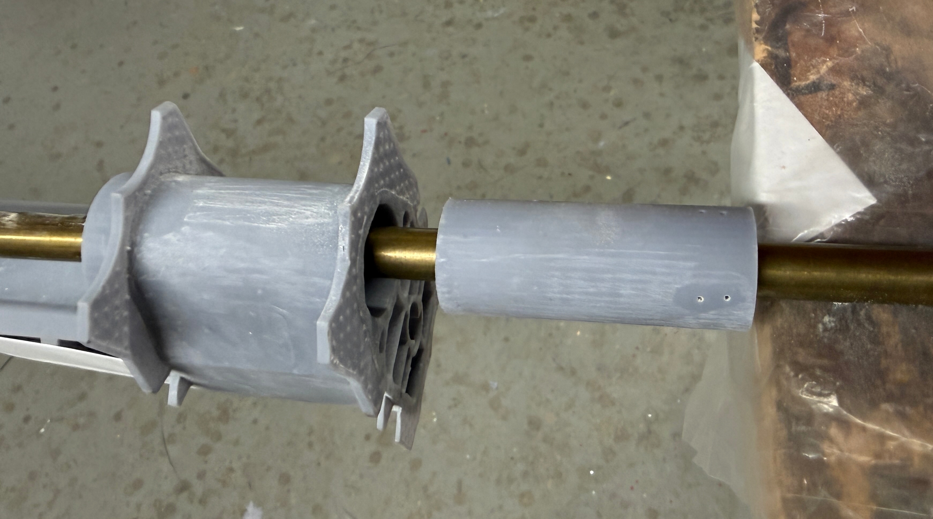
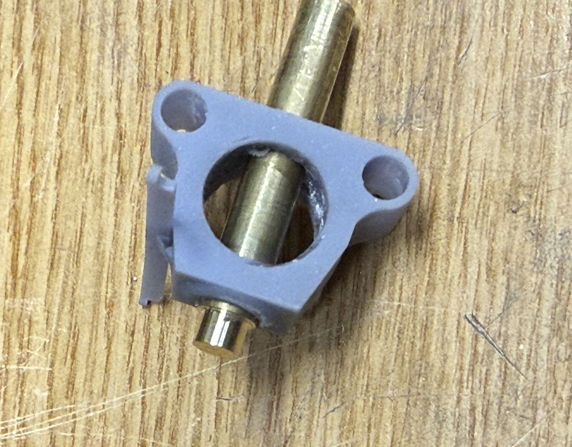
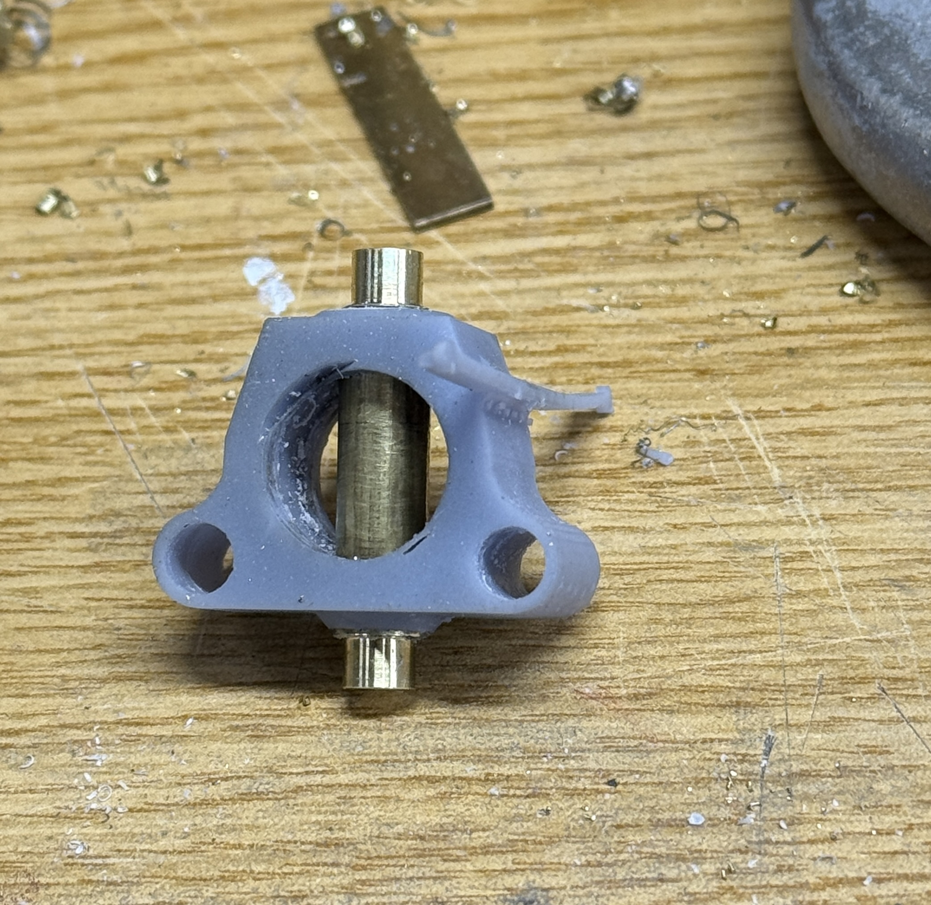
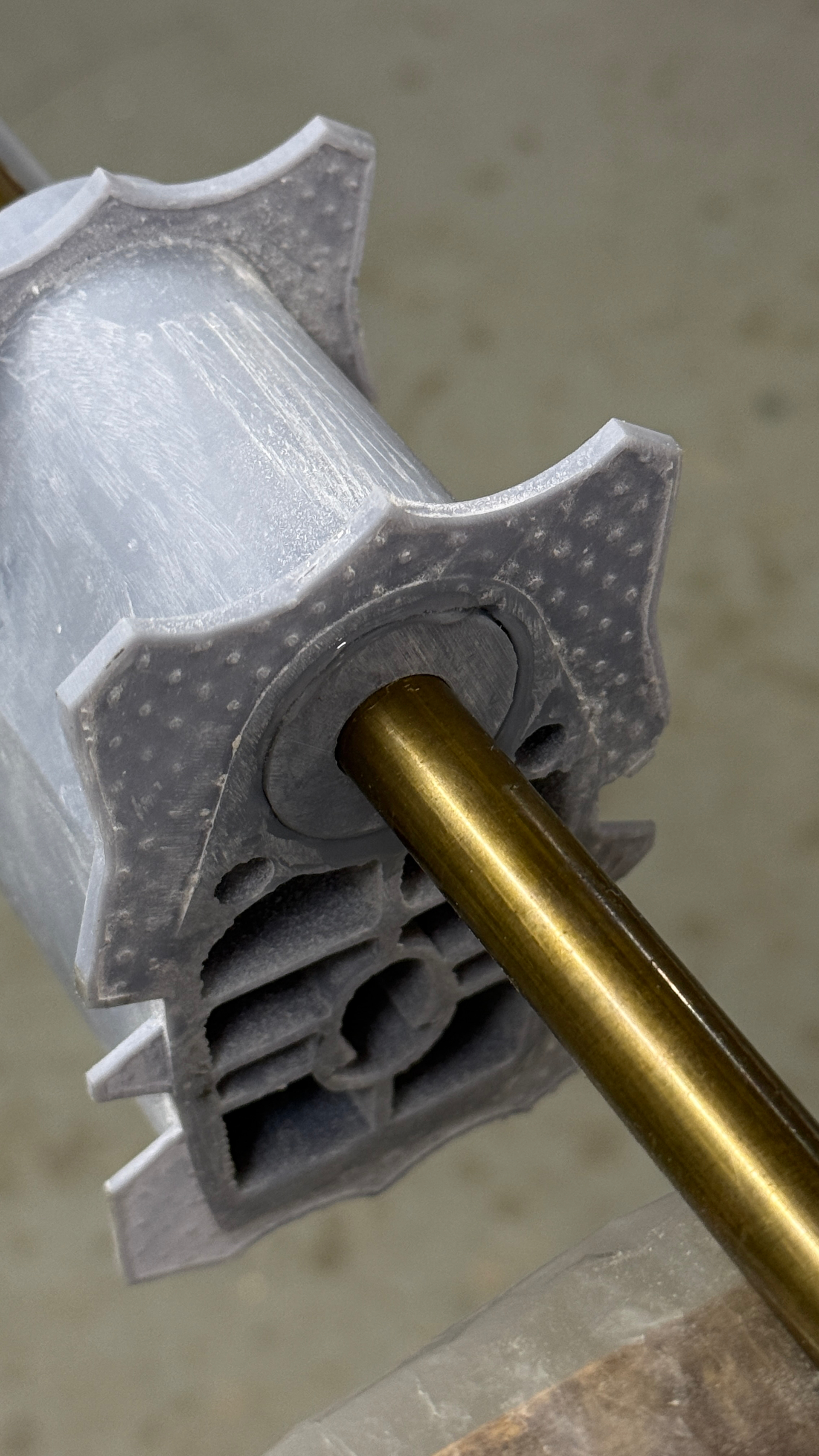
Here it is after epoxying the sleeve into position. I used the rudder stock to hold the part in alignment while the epoxy set. With this being the actual part I’m going to use, it will need some more cleanup.
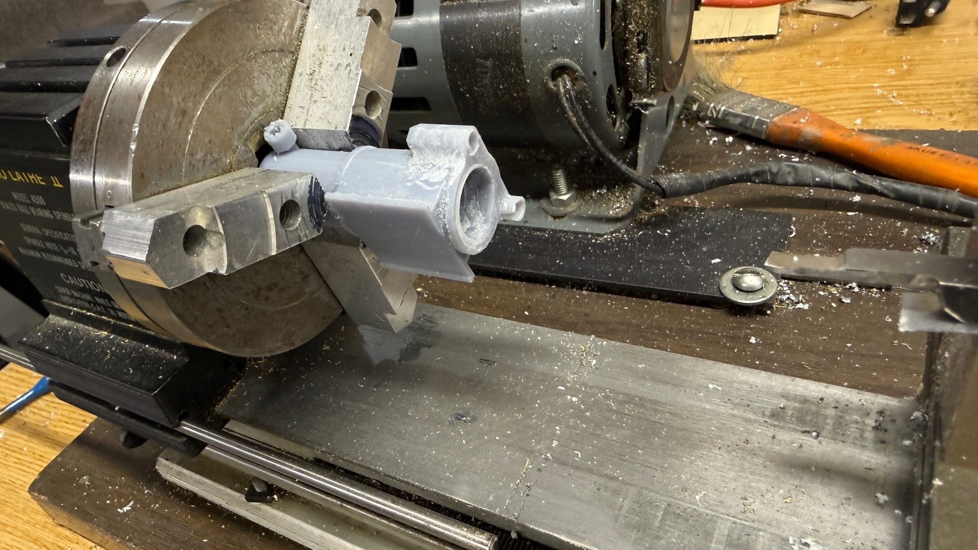
For the Servo Arm, I had some 1" round brass stock. First I had to hacksaw a chunk that would fit onn my tiny lathe. If I had a “real” lathe with a reasonably-sized hole through the arbor, I would have just chuck the piece in and got to work. I had to first get my hacksaw at my daughter’s house. My son in law borrowed it and forget to give it back. I rarely use this, but when you need it, there is no substitute.

I turned the lug end to just fit into the hole I cut in the brass arm. It didn’t have to be a tight fit. The whole deal is going to be soldered together.
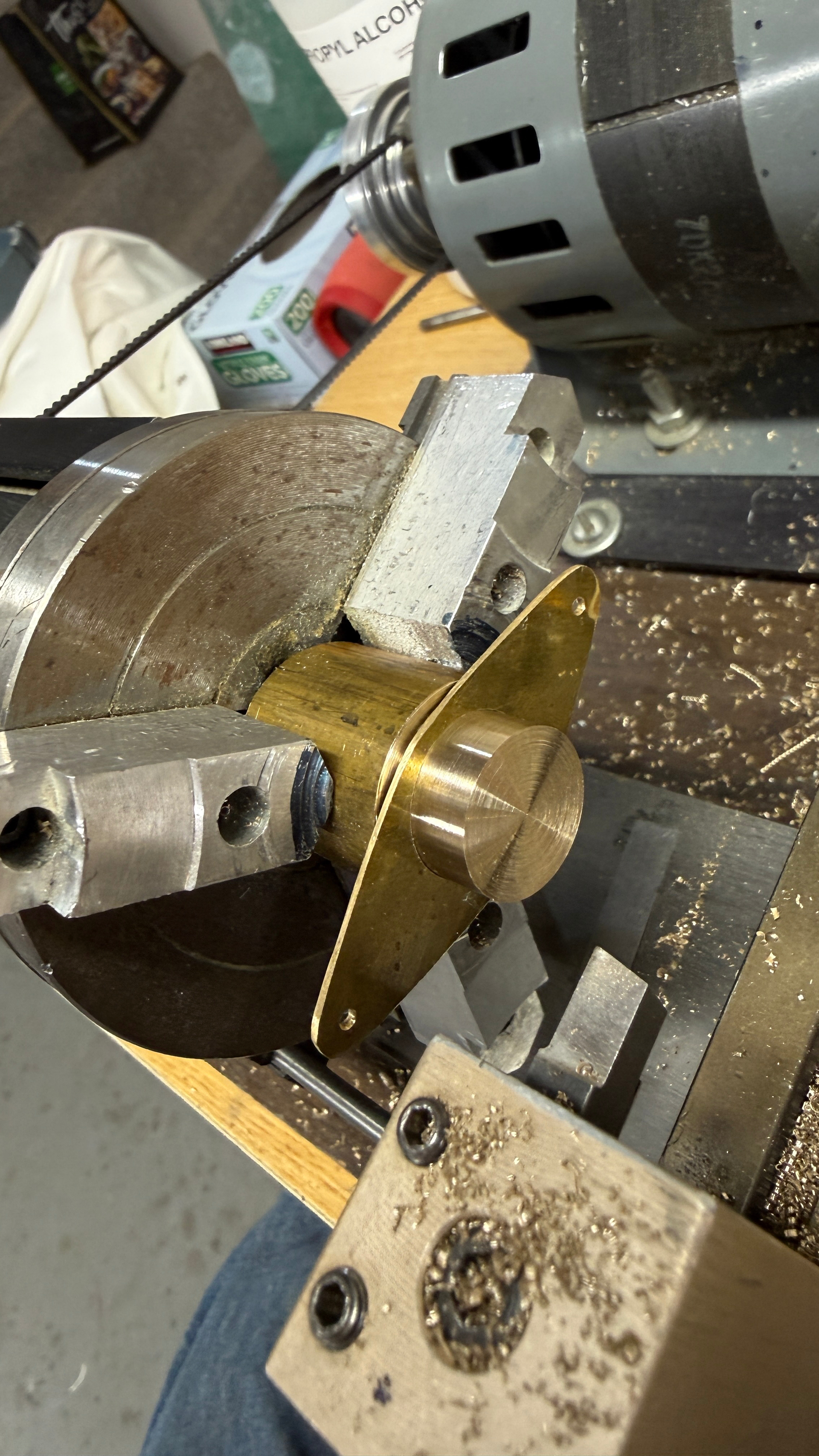
I turned the part around and turned the o.d. of the body so it coincided with the edges of the arm. I couldn’t cut it all the way back to the smaller diameter, and didn’t trust the relatively light 3-jaw chuck. I also have a very robust 4-jaw independent chuck and put that to use to ensure that the piece is concetric and true. I use a Starrett Last Word dial indicator to get the runout to about 001".
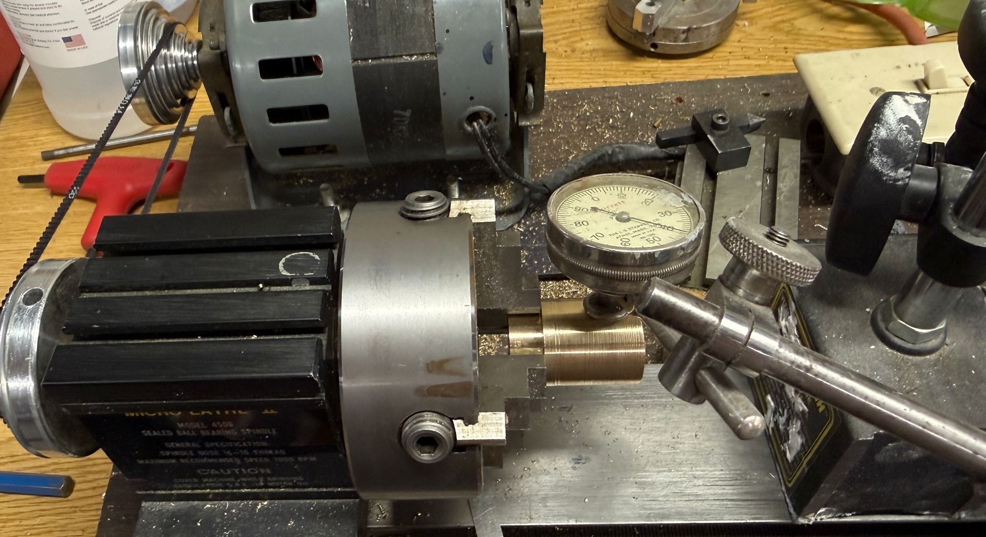
After turning the o.d. I needed to chop off a whole lot and again used the hacksaw to do this. I have cutoff tools, but the lathe isn’t powerful enough to do very deep cutoff operations.

After cutting the excess I faced that end, center-drilled a starting point and drilled through with a smallish diamter pilot drill. I followed this up with the largest drill my machine can handle—1/4"—and then used a small boring bar to open the hole to a clearance fit of the rudder stock.
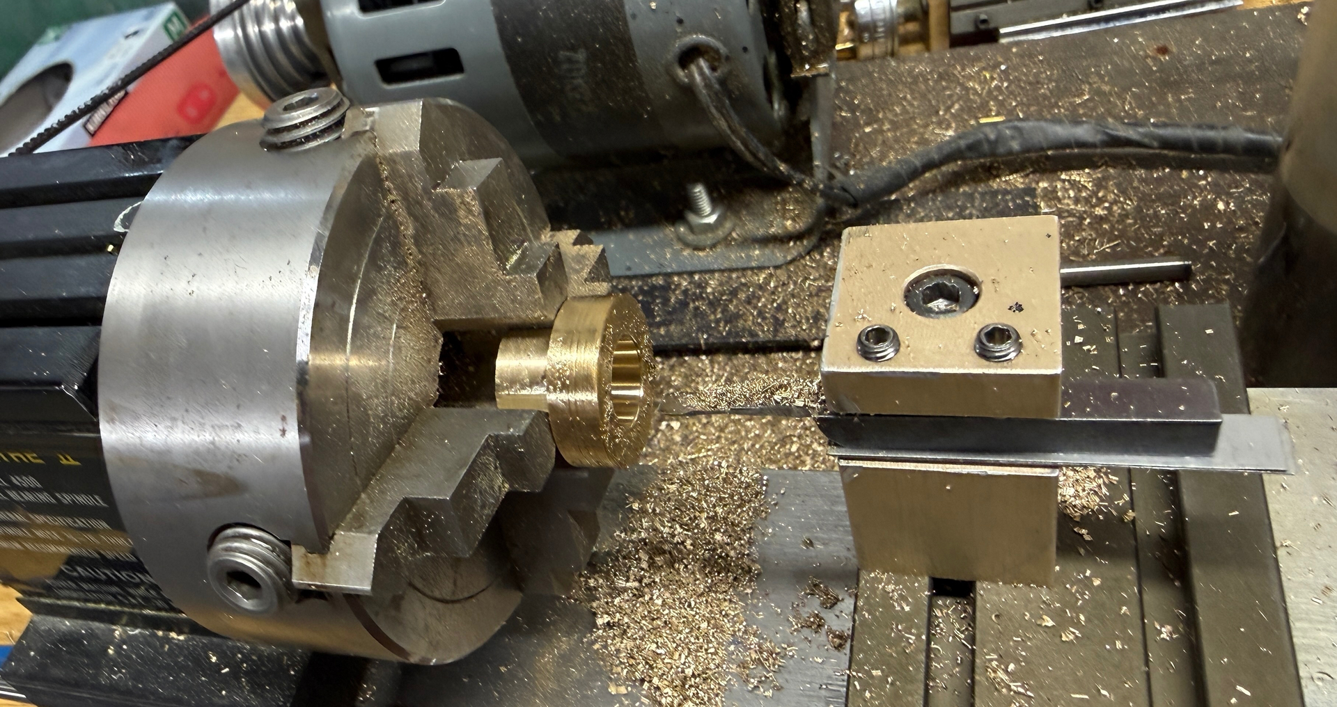
I turned it around again and shortened the narrow end. I only need a lip on that end for the soldering. I need all the stock on the fat end to handle the set screw, which I will do tormorrow.

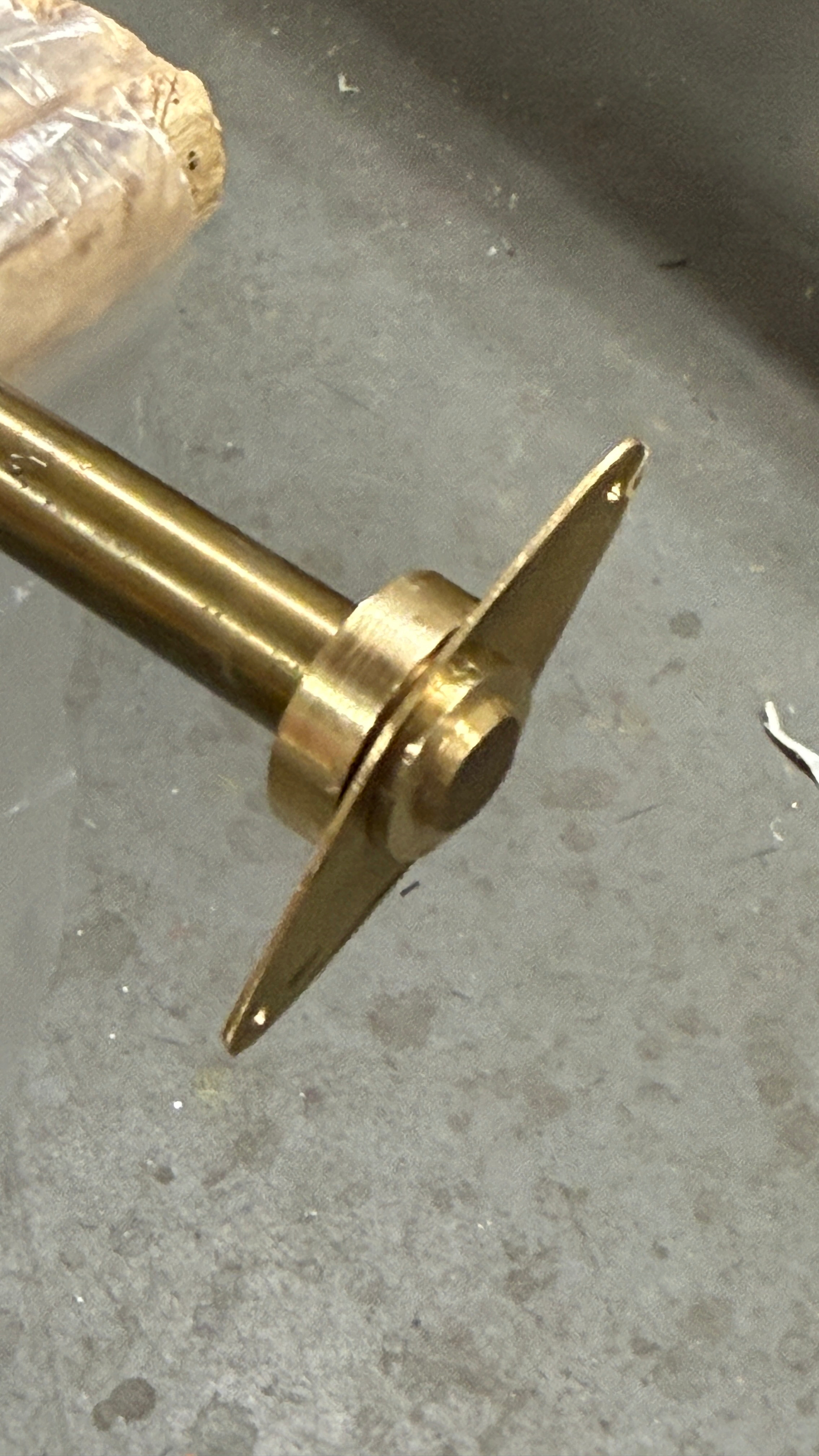
Here it is cleaned, but not yet soldered.
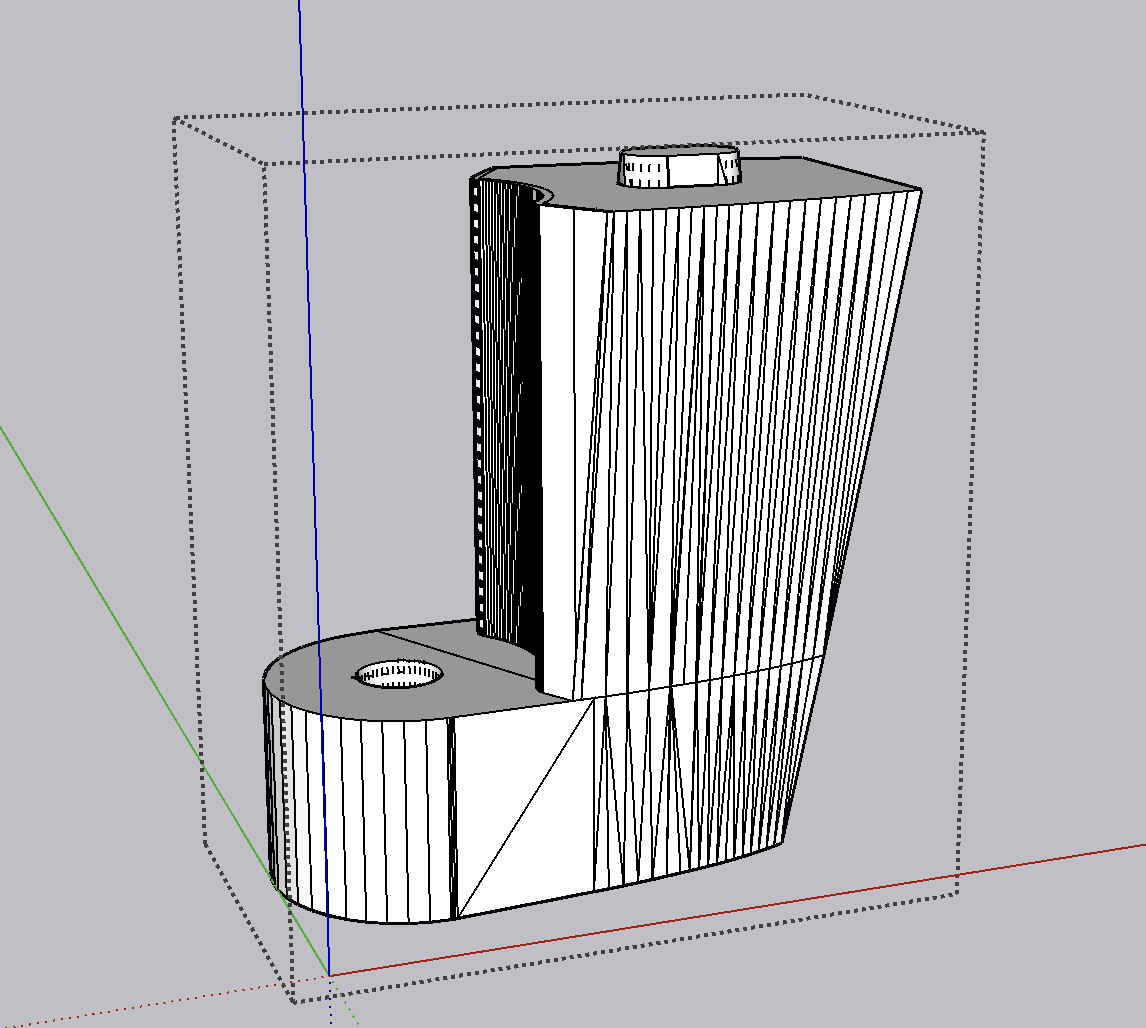
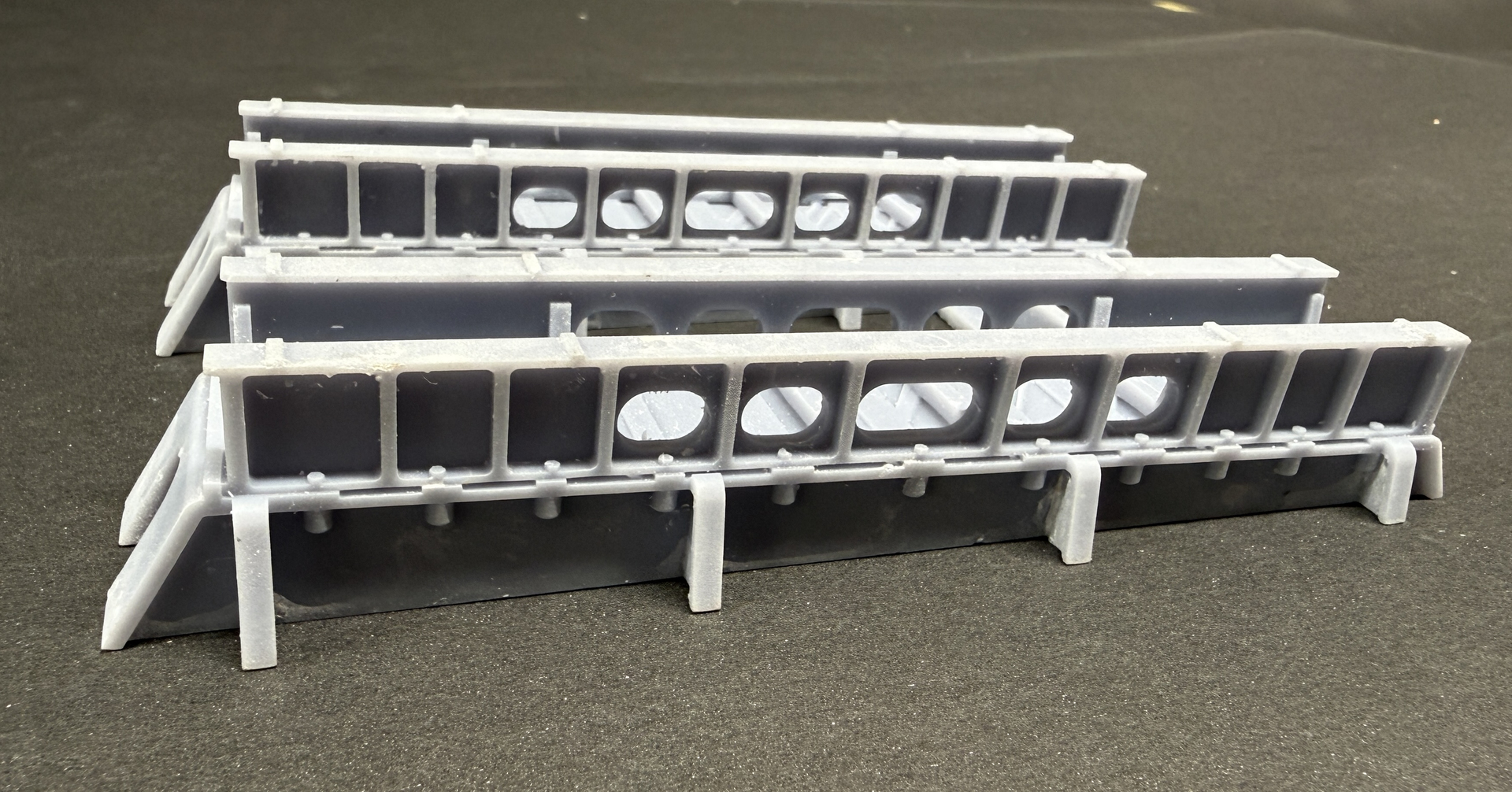
I also got reasonably successful prints of the upper rudder support, but there was a drawing error in it. I could still make it work and my upper bearing just about fits. Need to relieve the hole slightly. I have modified the drawings and will attempt to reprint.

Now to the horrow show.
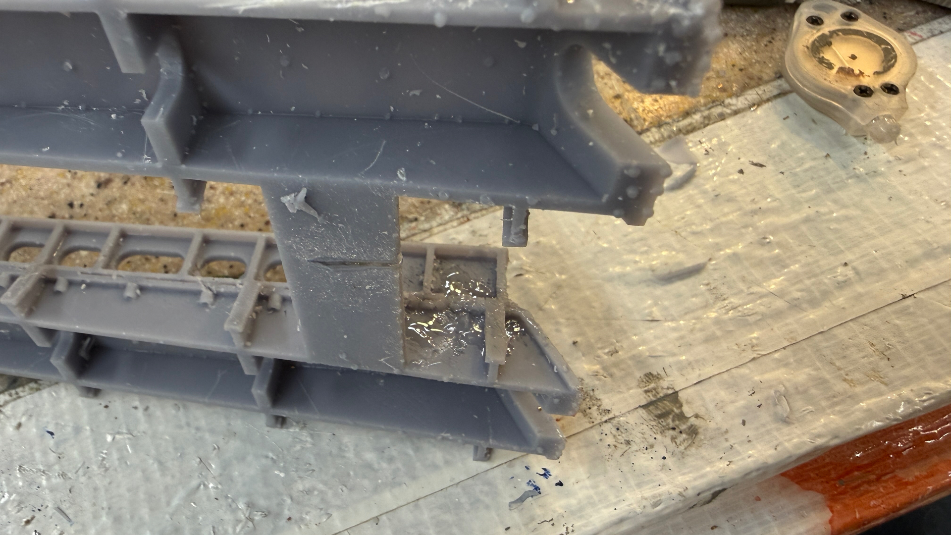
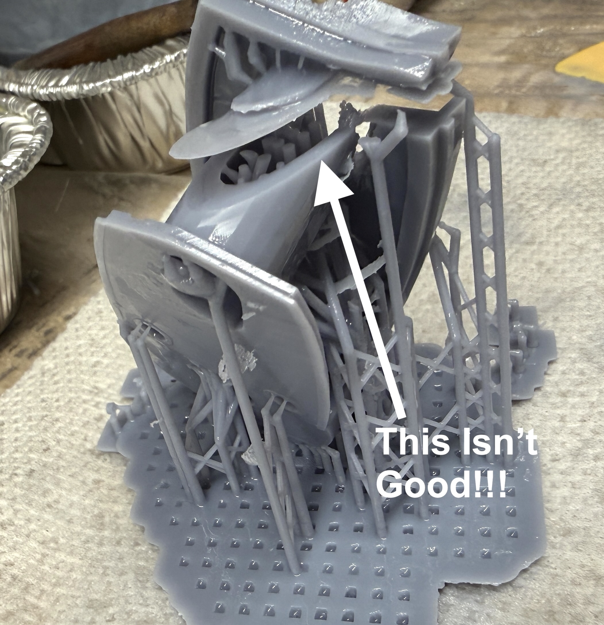
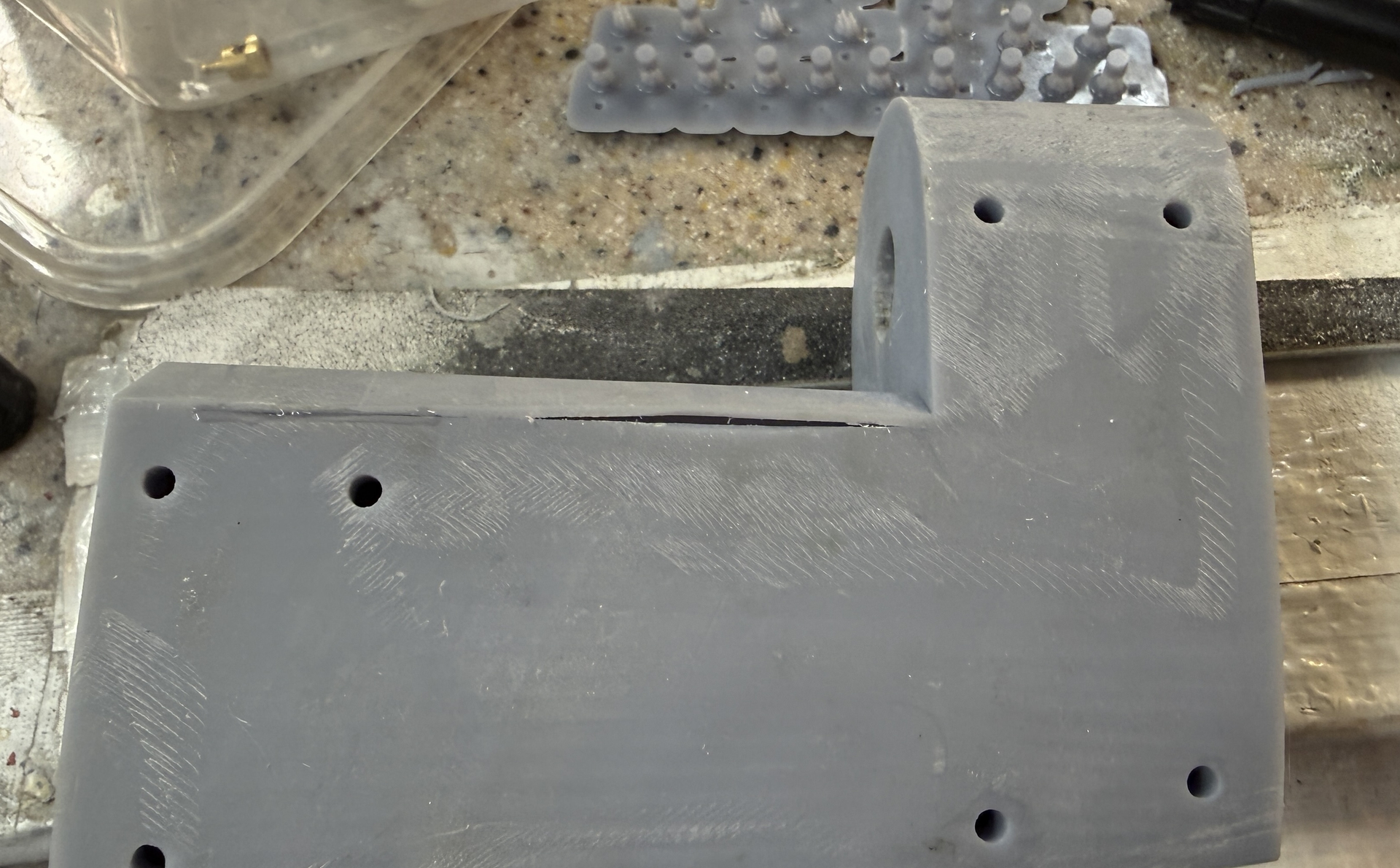
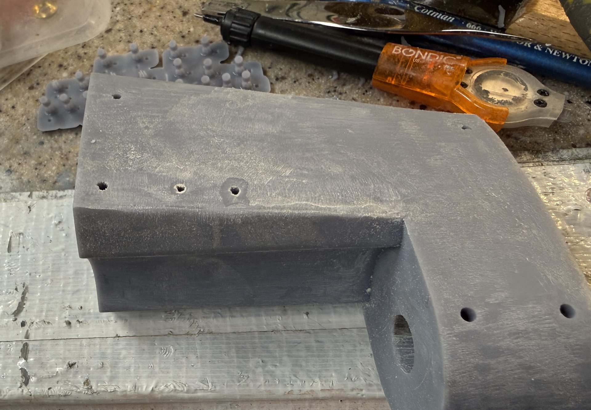
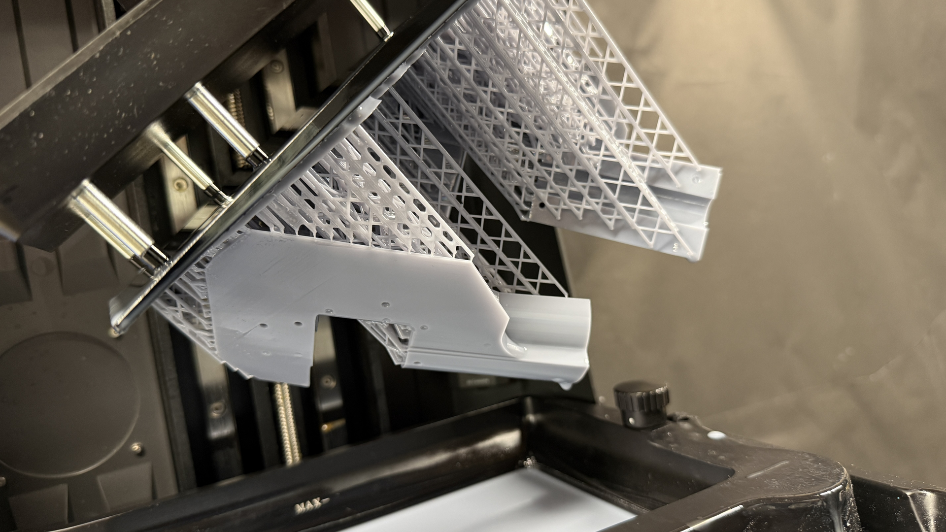
This is what a severe delamination looks like.

Notice that the initial part of the raft is firmly attached to the build plate, but the transition layers are not. I did a Google search to find out causes for this and made modifications to the printing parameters concerning the raft. Those changes made things worse, not better. I’m at a loss since the first print, while incorrect, did actually print. Everyone I attempted after that had some degree of delamination, from mild to wild. The first five layers cure for 8 to 12 times the working layers exposure time. I was curring my rafts at 35 seconds, but after reading about the problem reduced it to 26 seconds. My exposure time is 2.1 seconds. Then for the next five or six layers, the exposure time is reduced by a linear progression until it reaches the working time of 2.1. This is where the trouble is and I don’t yet how to fix it.

It’s why that reject part is so important.

Because of the misshapen supports, there’s a good chance that there is some resin stuck to the barrier film. If there’s even a very tiny bump on the film, the auto-leveling will report an error. This means, removing and emptying the vat through a fine mesh filter to catch anything floating in the resin, removing any bumps on the film and replacing and refilling the vat. It’s a messy part of the process that I don’t relish.
4 Likes

Similar effect for me as after too much horseradish. Commiserations, I’ve no idea the cause but the result could be salvaged as Modern Art if painted imaginatively. Reminds me a little of Roger Dean’s 1970’s album covers for Yes. That aside, fascinating engineering Myles, another great project.

That’s for the moral support Tim. I’m still not sure what was going on, but I suspect that the size of the raft was the outer limit of the printer’s capacity. Read on…

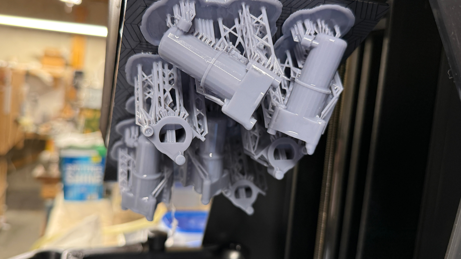
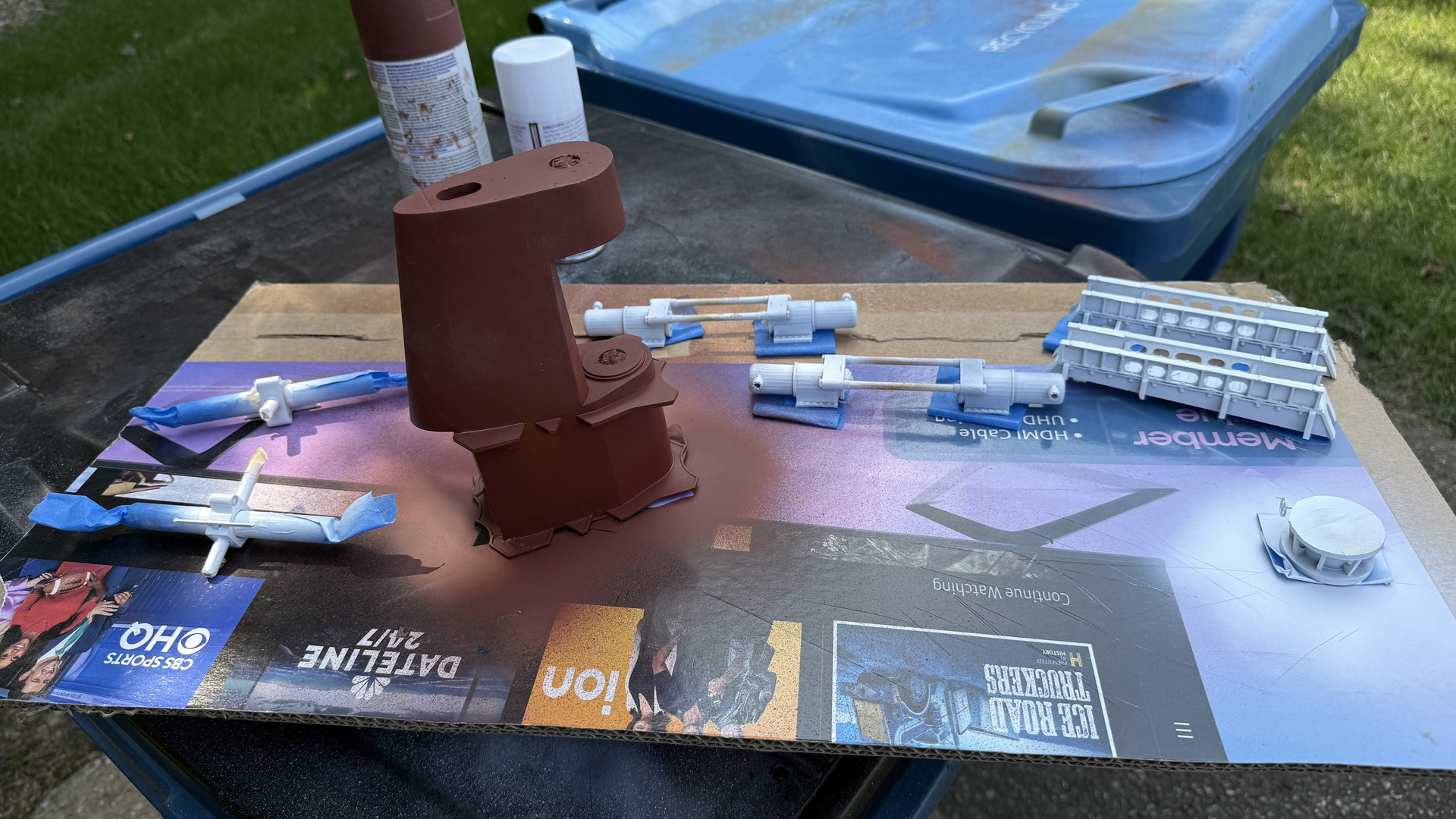
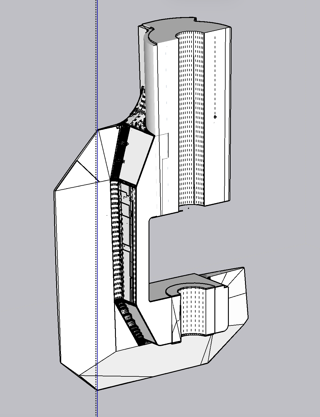
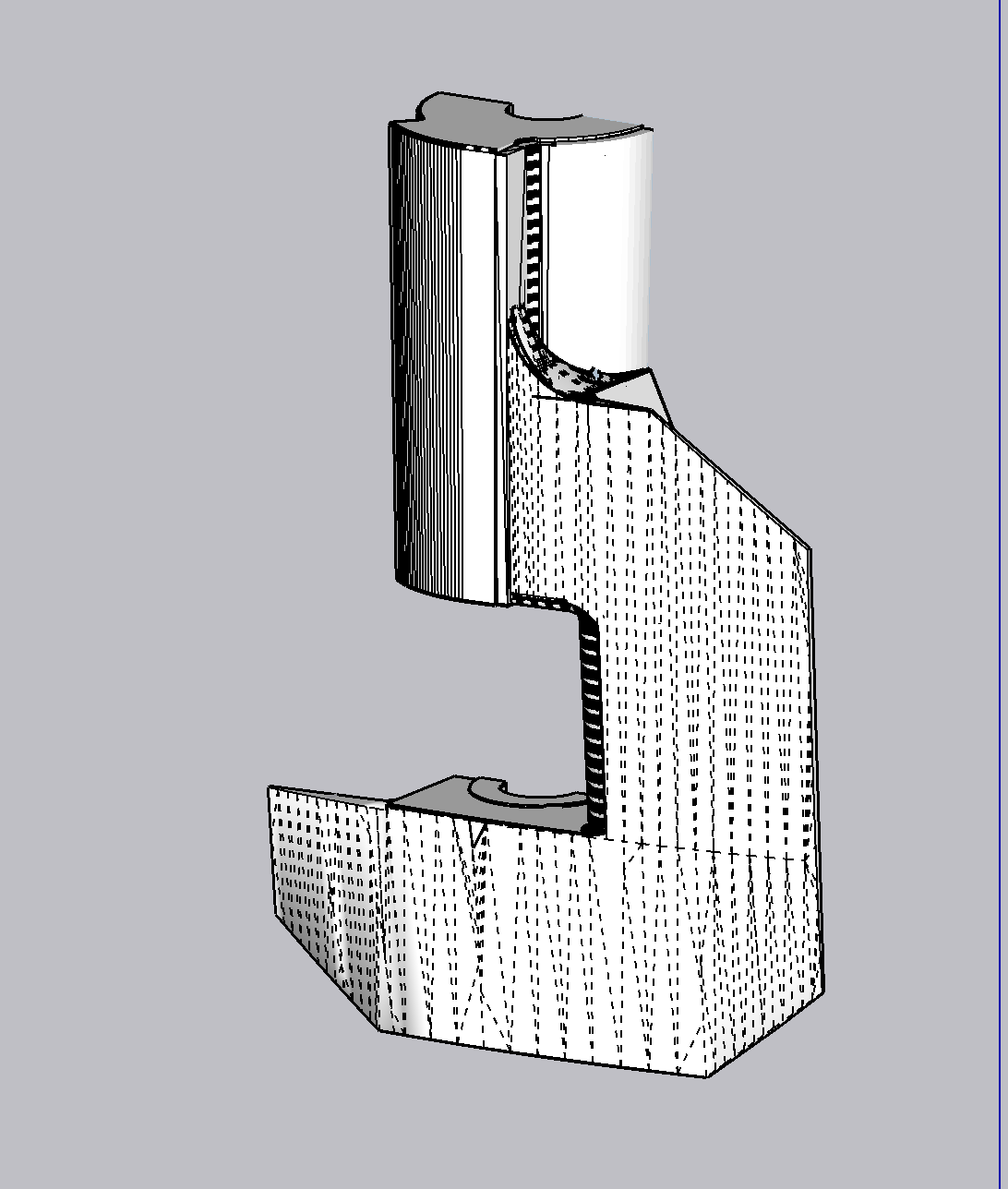
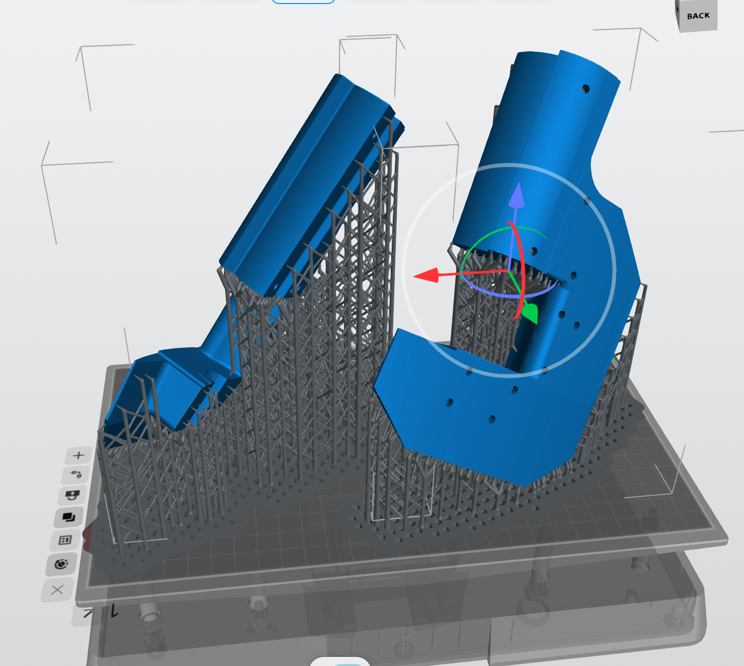
It happened one more time—which makes 5 attempts to print a successful rudder hub—so it’s time to rethink the problem. I was told that probably breaking it into sections and printing that way would solve the problem, and that’s what I’m doing. I 3/4 through redesigning the rudder hub in three sections. They’ll print on the machine better and much faster since the printer is only concerned how high something is (number of layers) to determine printing time.

Meanwhile, the reprinted rudder top frame, rudder crank and ram cylinders printed well and will be used. So it’s really a function of the large size of the raft that seems to be causing the trouble.

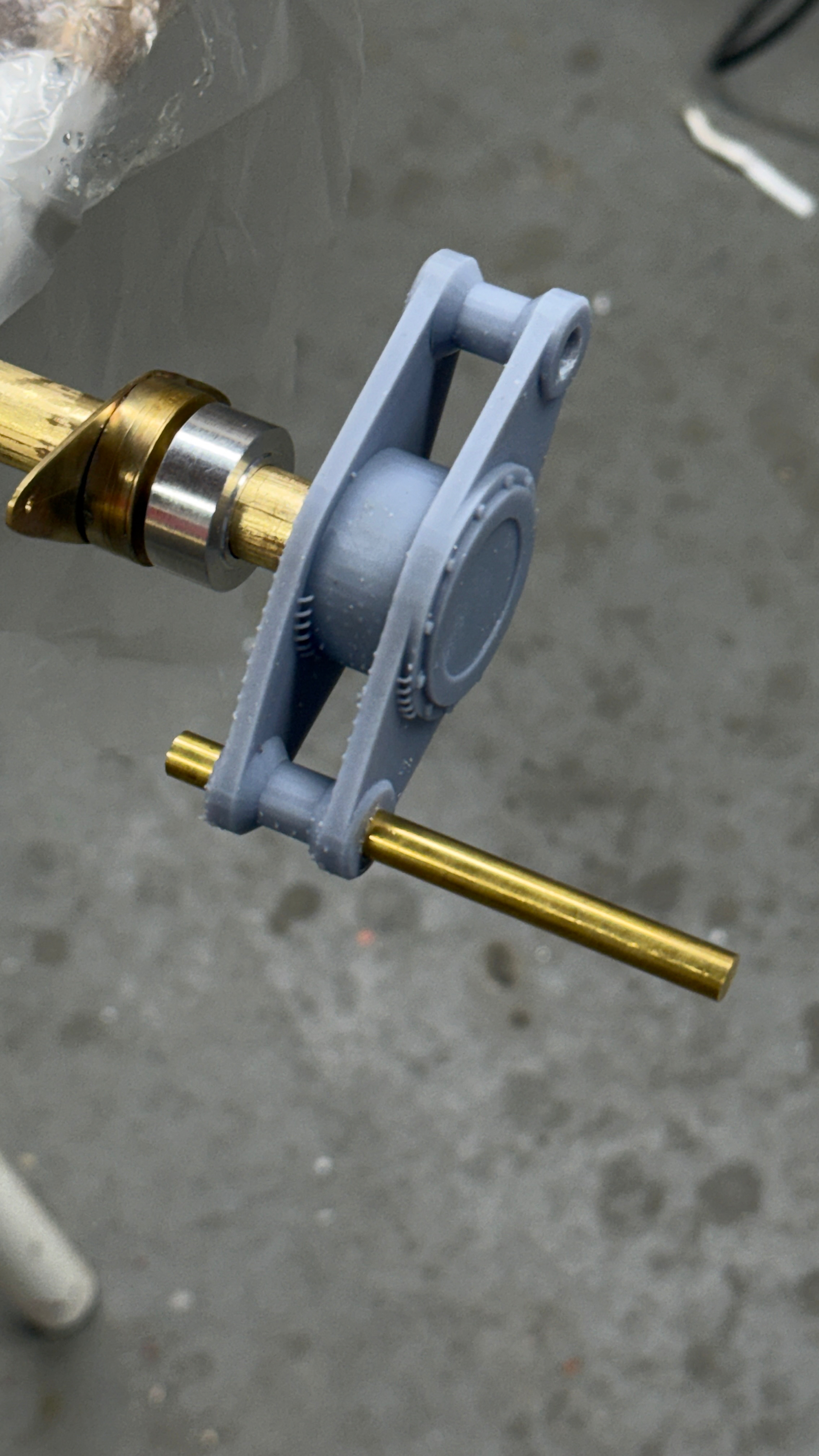
With just running a 1/4 drill by hand through the crank’s pivot hole, the 1/4 brass rod, that’s going to ultimately form the pivot points for the ram rods, fit perfectly.

I have to turn the ends down to the snug fit inside the small ram rod ball bearings. Will do on Monday. I hadn’t even post-hardened the crank nor did final finishing when I took the pic. Also shown on the above is the turned thrust bearing that will help support the weight of the rudder stock and focus its weight on the lower bearing’s rotating inner race.

I printed extras along with the rudder upper frame and redid the frame to make the handwheel more robust and did better job of supporting it. So it’s perfectly formed in this interation.

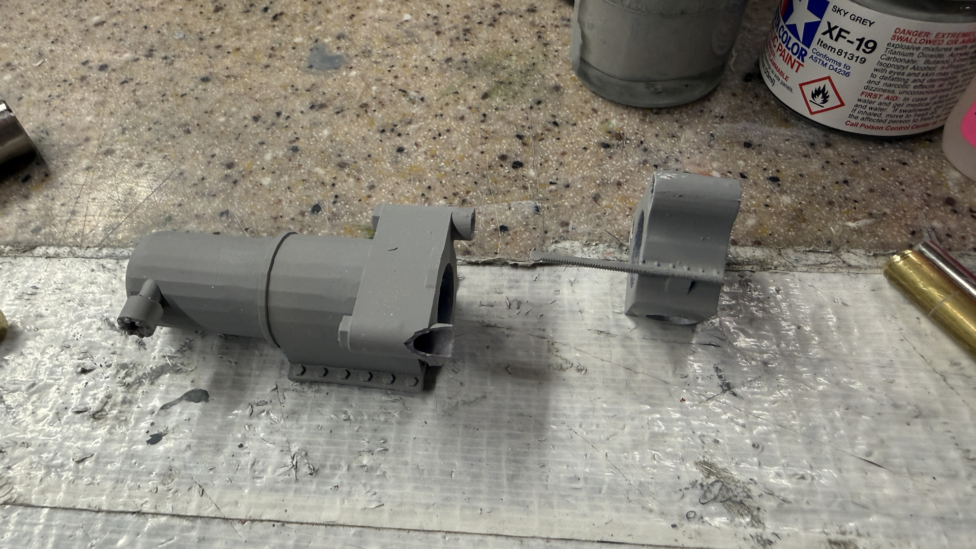
The cylinders are okay, but there will be some post-print trimming needed. There is some unwanted extra resin in the bore opening that I will have to remove. Something about the support scheme promoted this malformation. I can always remove stuff. Much easier than adding anything that’s missing.

After cleaning out the vat for the 5th time, I reset the printer to print the cylinders. We went out to the movies and when I got home saw the job was showed “COMPLETE” on the LCD panel. When I lifted the lid, I saw this.

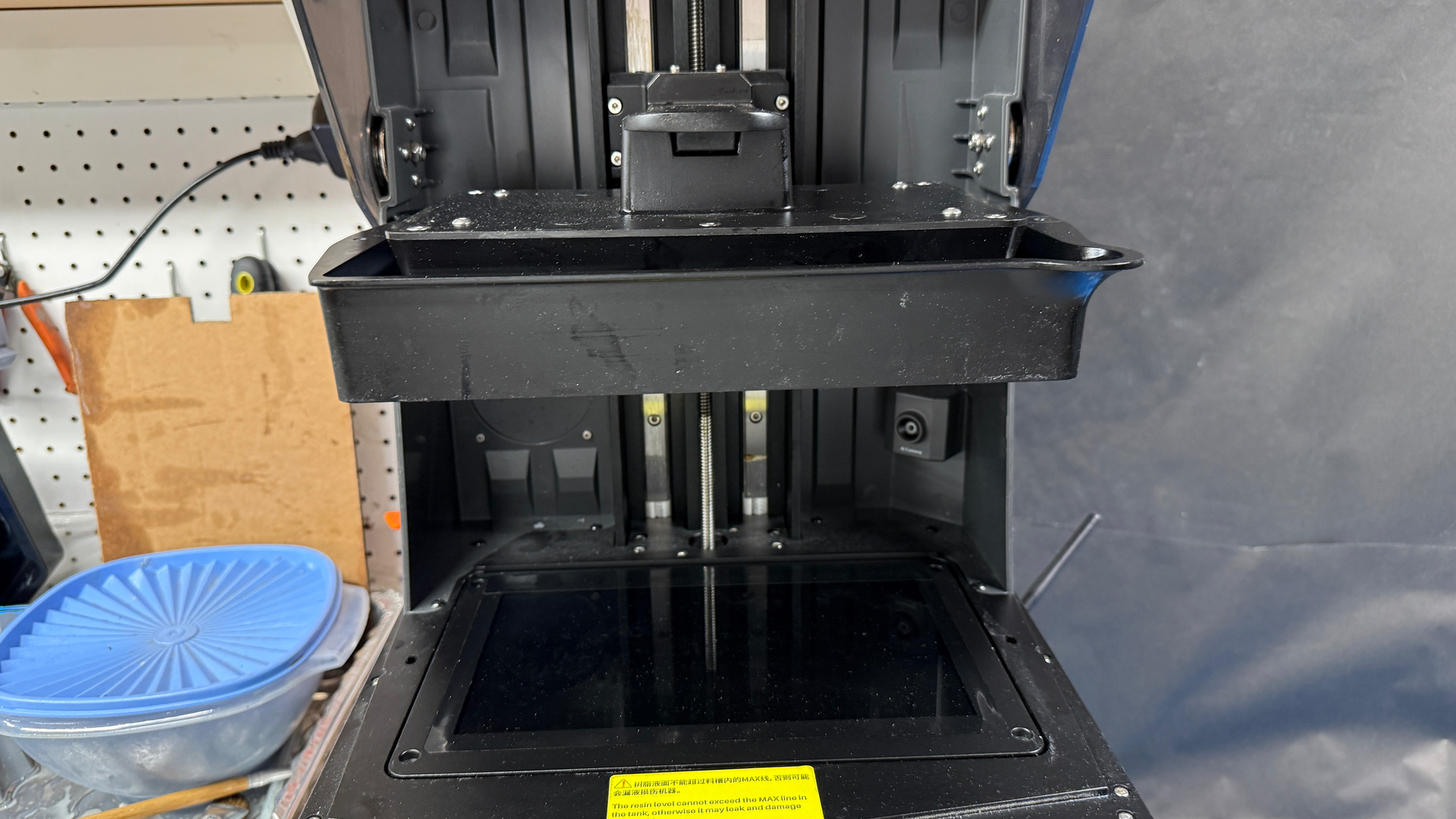
In my haste to get something accomplished on the printer, I started the job without installing the vat hold down screws. The suction on the barrier film is so high, that after printing a few raft layers the entire vat was now rising and lowering with the build plate, and it lifted the whole deal to the finished postion while printing absolutely nothing! Since nothing was actually printed other than some prelimenary raft layers, nothing was stuck to the film. I just popped the errant layers off the build plate and started the job again… this time with the hold down screws holding the vat down. This was probably the most bone-headed stunt I ever did with the printer. I will not repeat it.

Work up yesterday morning at 5:00 am, and laid in bed for a couple of hours building the project in my head. I came up with 13 decisions on moving forward. I got up at 7:30 and wrote them down so I wouldn’t forget them.

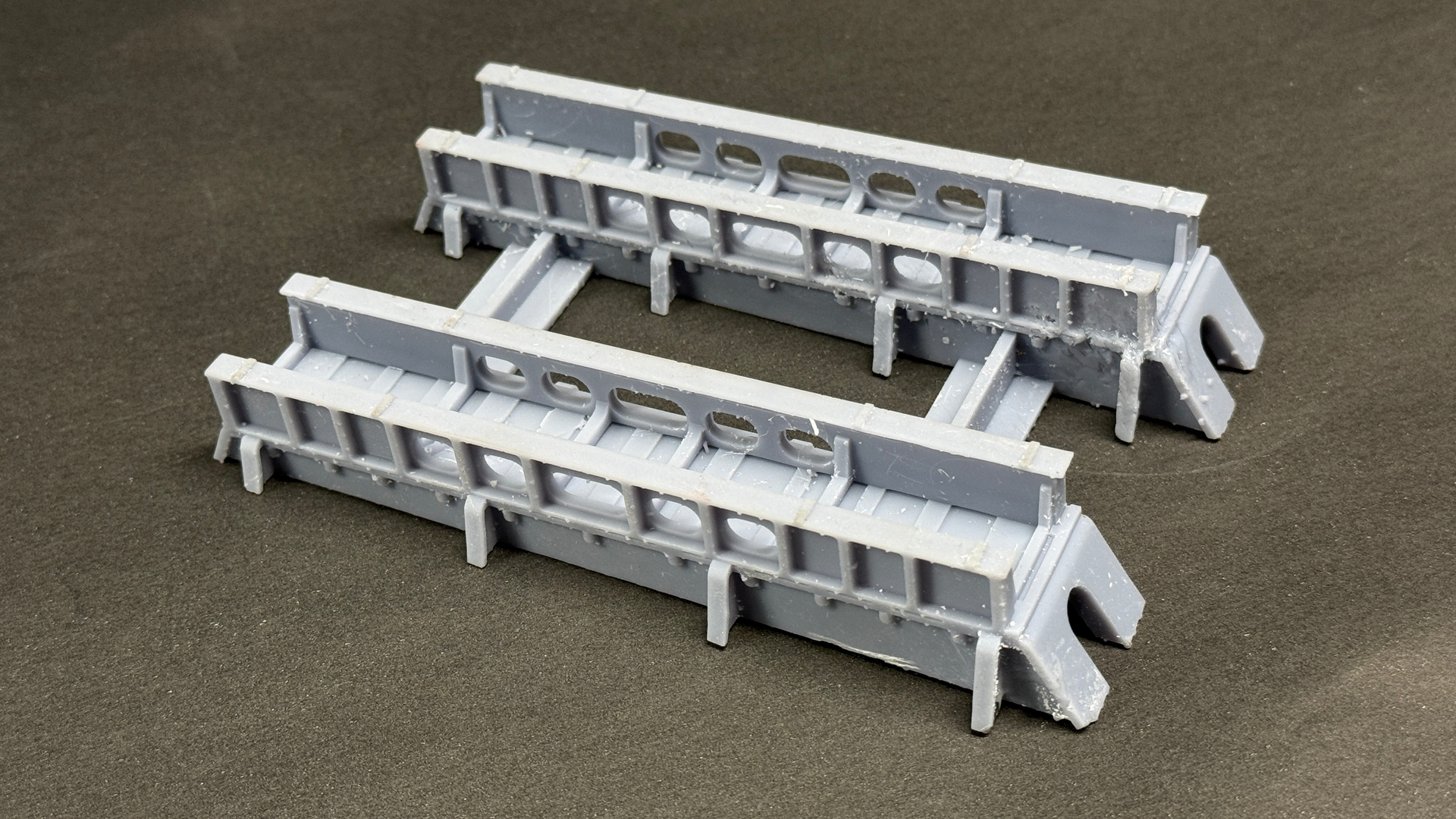
I discovered that if I printed the upper foundation frames as I drew it, the crosshead and lower ram rods would have no where to go. The frame needs to be open on top at least to foreward cylinder.

I also decided to print the rudder framing complete and do it in sections like I’m now doing on the rudder hub. Still haven’t decided on sheathing with styrene or balsa. Both have their pros and cons. Styrene won’t require filling to get a smooth metal-like finish, but balsa responds better to gluing with epoxy or CA.

I also with need some metallic thrust washers wherever there’s UV resin-on-resin contact.

And I did some research on adding a sound module driven by the Arduino so I can have hydraulic motor sounds sychronized to the rudder’s motion. I was able find and download hydraulic machinery sounds and found that with some clever programming, the Arduino can control two things at once. The little Mini-SD Card player is less than $10 for two of them. And I have a speaker that would work. So it will not be expensive and adds another dimension of interest to the project. I have no idea what the steering gear actually sounded like. There are no operating battleships to hear it. I suppose other large ships with massive rudders would have similar sounds, but how do I capture them…. Hmmm.

The real fun of these kinds of never-before-done models is the imagination I have to generate to pull it off. And I’m turning 81 next Thursday. Age is just a number!

5 Likes

I posted my printing screwup on a FaceBook affinity group for Elegoo Saturn users. I got a lot of funny comments and many from folks who have done the exact same thing. Then today, I attempted to run a job with the build plate off the machine. I was working away on other stuff. When I checked back I got a “vat level too high” error which stops the machine. When I opened the lid, I see no build plate. It was minding its own business on the table next to the printer. I said I wasn’t going to make the last mistake again. But that didn’t preclude making a completely different mistake.

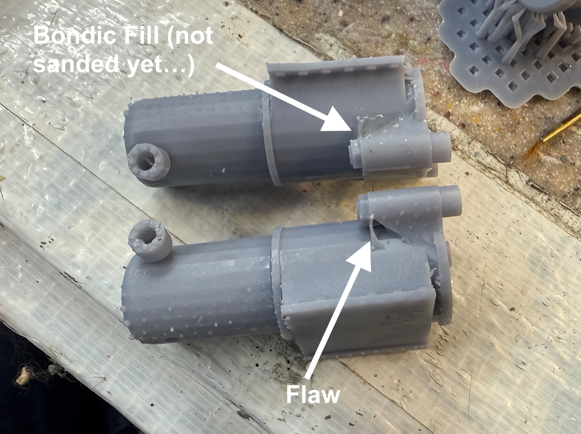
Got reasonable prints of the cylinders however, there’s some craft work needed to make them workable. I had to run a #22 drill through the crosshead guide holes so the polished stainless rods slipped in. I also had to do a Bondic repair on a small area on the same crosshead guide lug that didn’t have adequate support. I will sand this area smooth next session and when painted will no longer be seen.

I also have to clear out the cylinder bores to remove that excees resin that formed there.

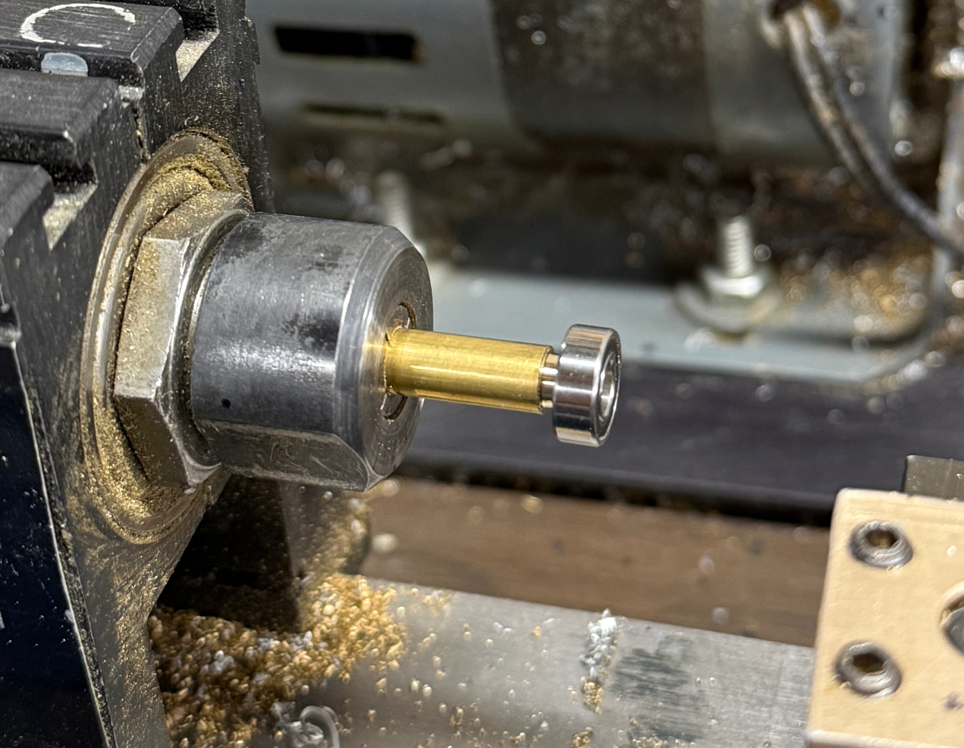
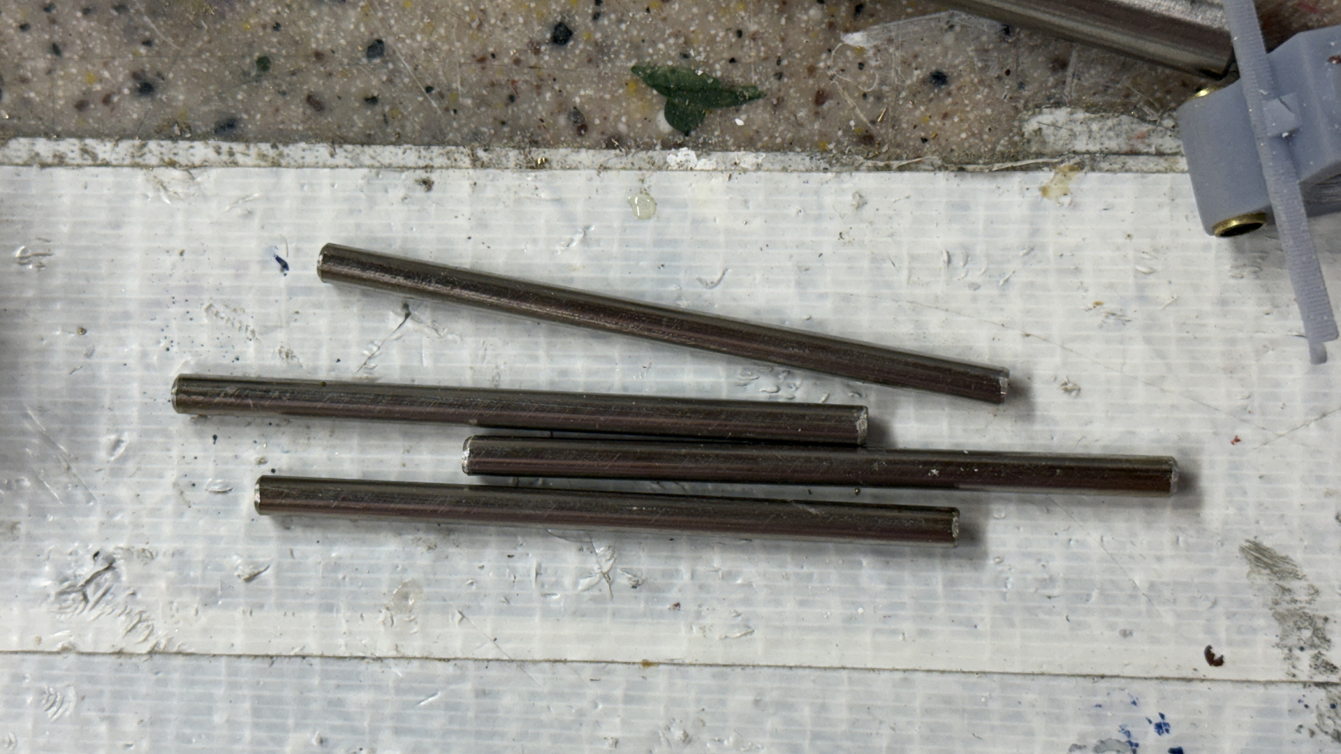
I then machined the crank pins that will hold the small ball bearings for the ram rods. This is for the rudder crank end. After I print the crosshead itself, I will machine two more of these.

The upper rudder frame printed perfectly and the ball bearing fit the bore perfectly. The handwheel and worm gear also printed well and, so far, hasn’t broken.

Here’s the rudder crank with the machined pins. I used thin CA to secure them. I will mask them when painting. I chose to install in the unpainted part because the fits are so tight that any paint in the bores would cause a problem.

The bearing fit on the pins is a slip fit, not press. The lower ram rods are hanging down and the could slip off the pins so I’m going to secure the bearing to the pin using some Loctite thread lock anerobic adhesive. I will also have glue the outer race into the ram rod for the same reason.

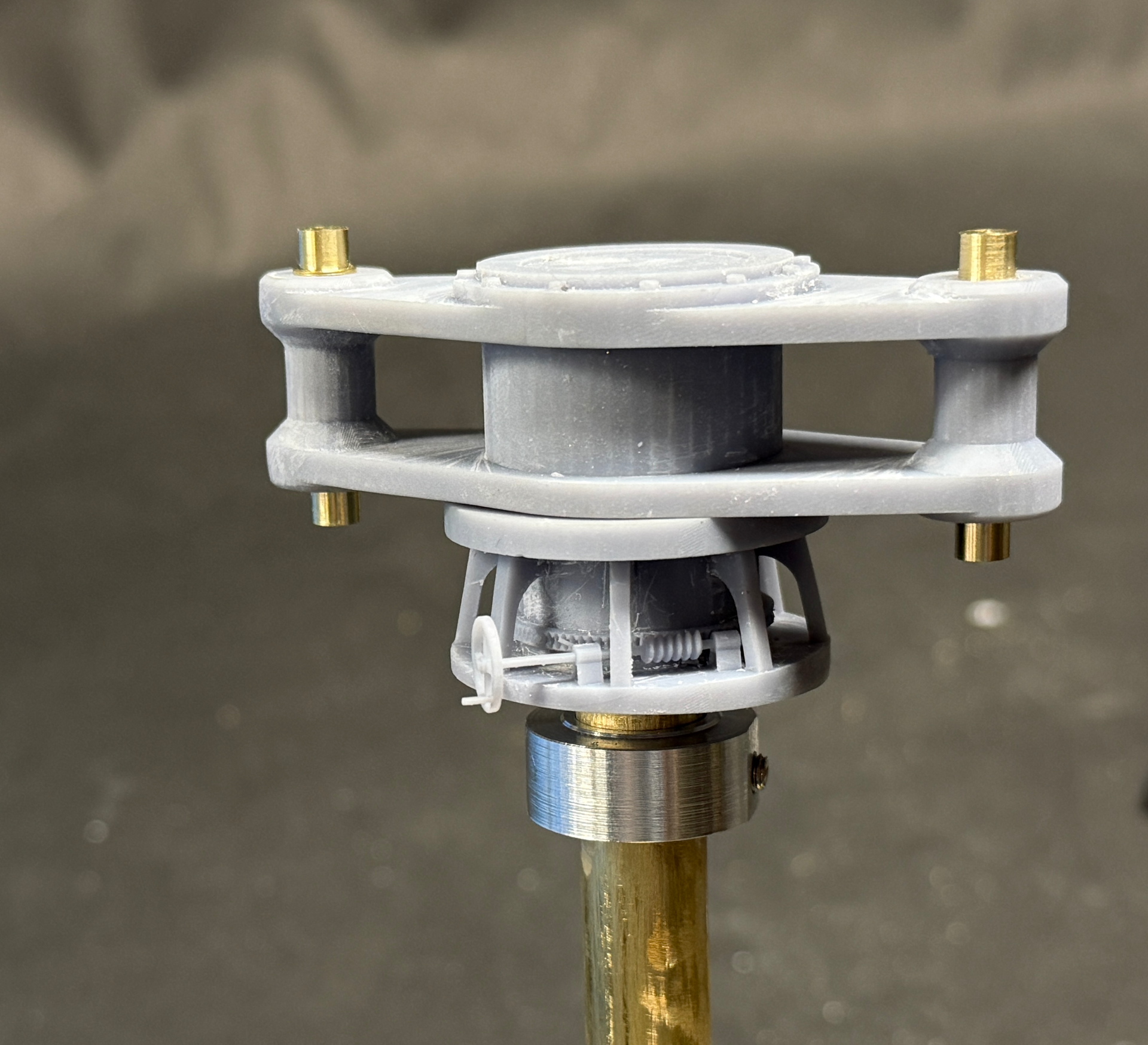
Here’s how the upper rudder pieces stack when installed in the ship.

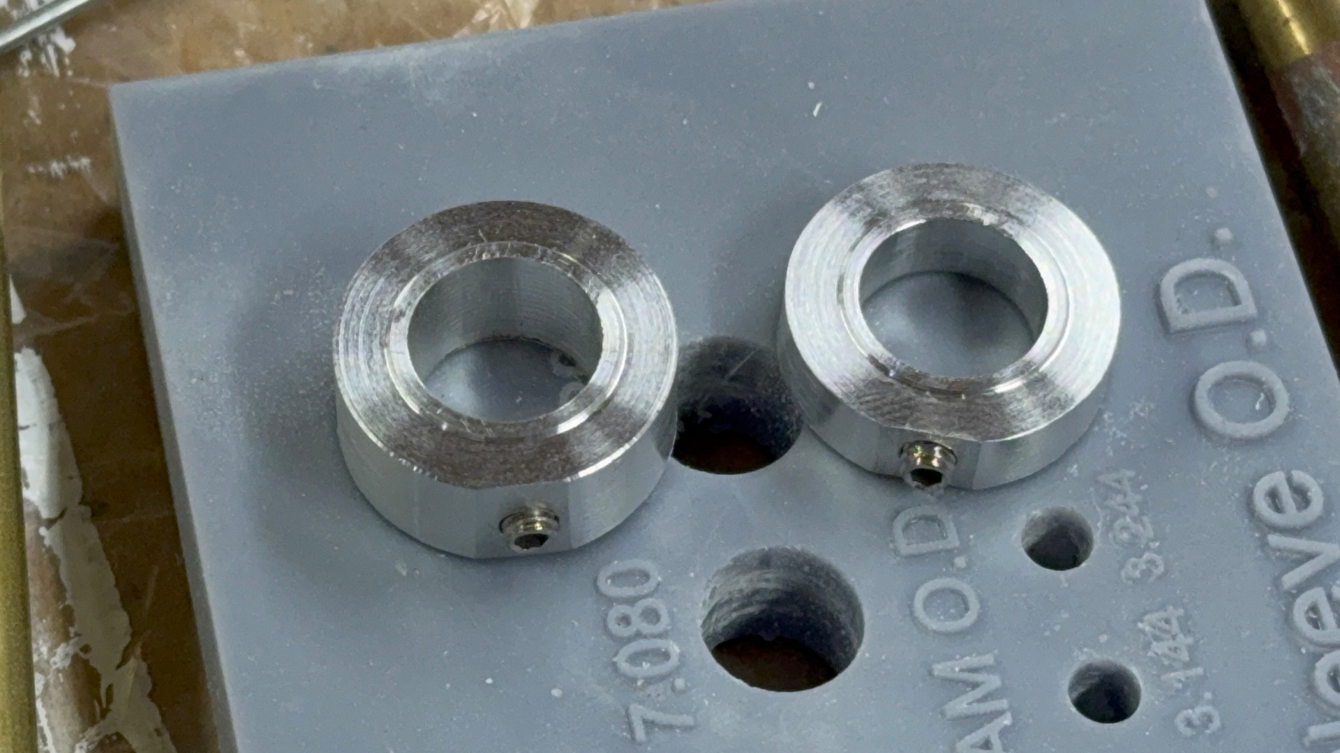
The last thing was machining another thrust collar. I made this one a bit thinner than the first. Fun turning project!

Set screws I’m using are Metric M4.

7 Likes

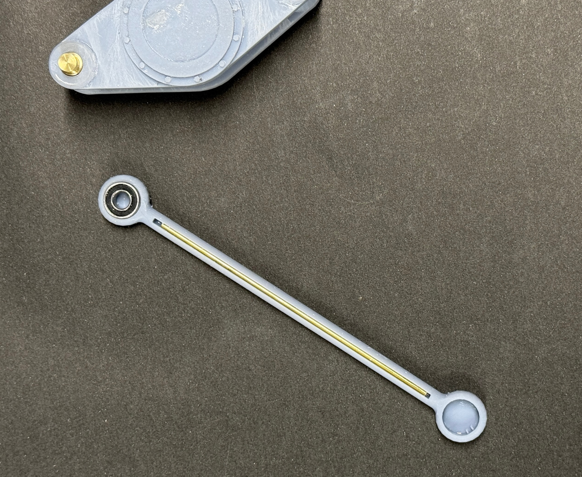
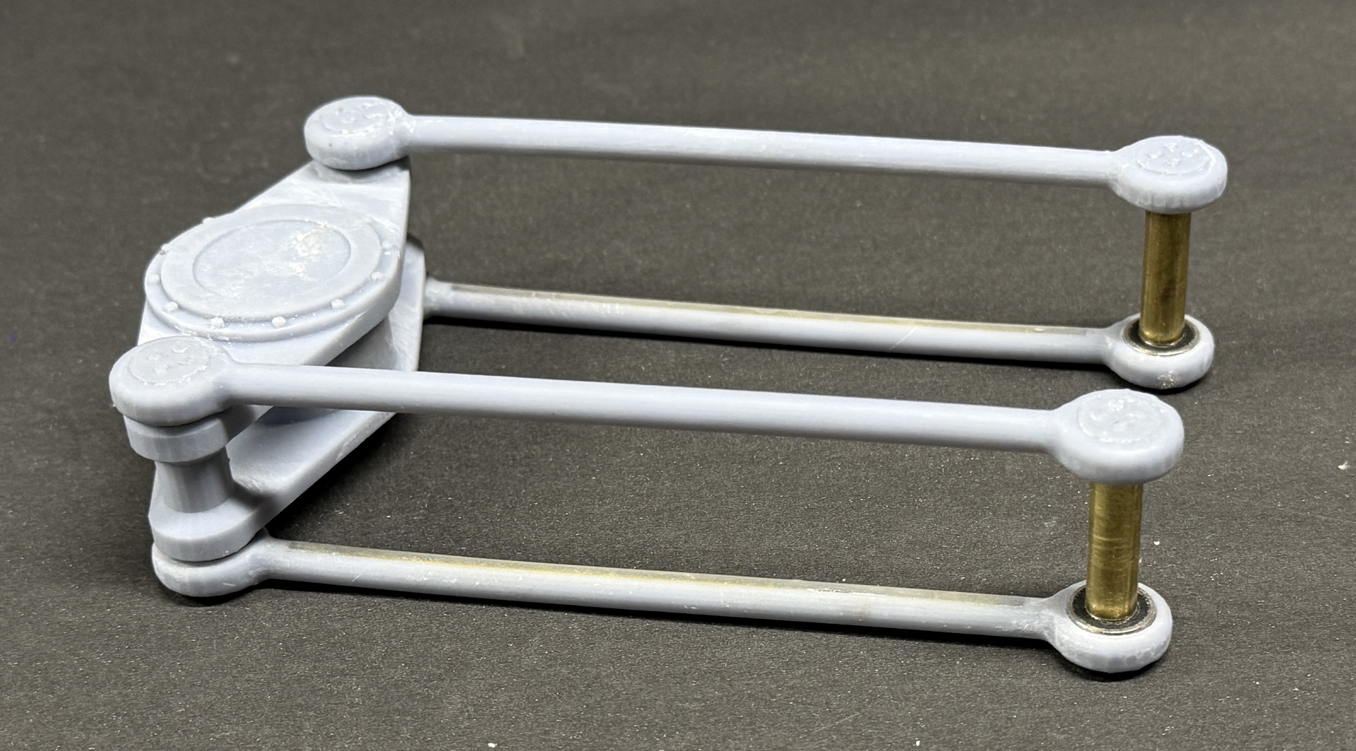
Today saw more successes. The scheme to create realistic and robust ram rods was flawless. The groove to receive the 1/16" reinforcing brass rod was sized perfectly. the rod required a little coaxing to slide down to the bottom. And the bore size to receive the ball bearings was aslo dead on. It took just a bit of pressure from my parallel jaw pliers to seat them to the bottom. It was very rewarding.

I used Bondic to fill and level the gap. You apply it in several layers, hitting each with the little UV LED, it cures in a few seconds.

Here’s what it looks like after sanding, but without paint.

I’m glad I spent the extra time creating that “Hole Sizing” test article. The printed bore diameter was a perfect press fit. All this work was done before post-curing. I wanted the resin to still be pretty flexible so any pressure would be accommodated and not forcing the ends to crack when the bearings were pressed home.

I finished all the finishing work on the ram cylinders. I made extra and used one to experiment on how to best remove that excess plastic what was semi-blocking the bore. At first I tried using the Dremel with a carbide routed, but it was way too rough and there was no way I could maintain concentricity. Chucking it in the lathe seemed like it could work if I was very careful.

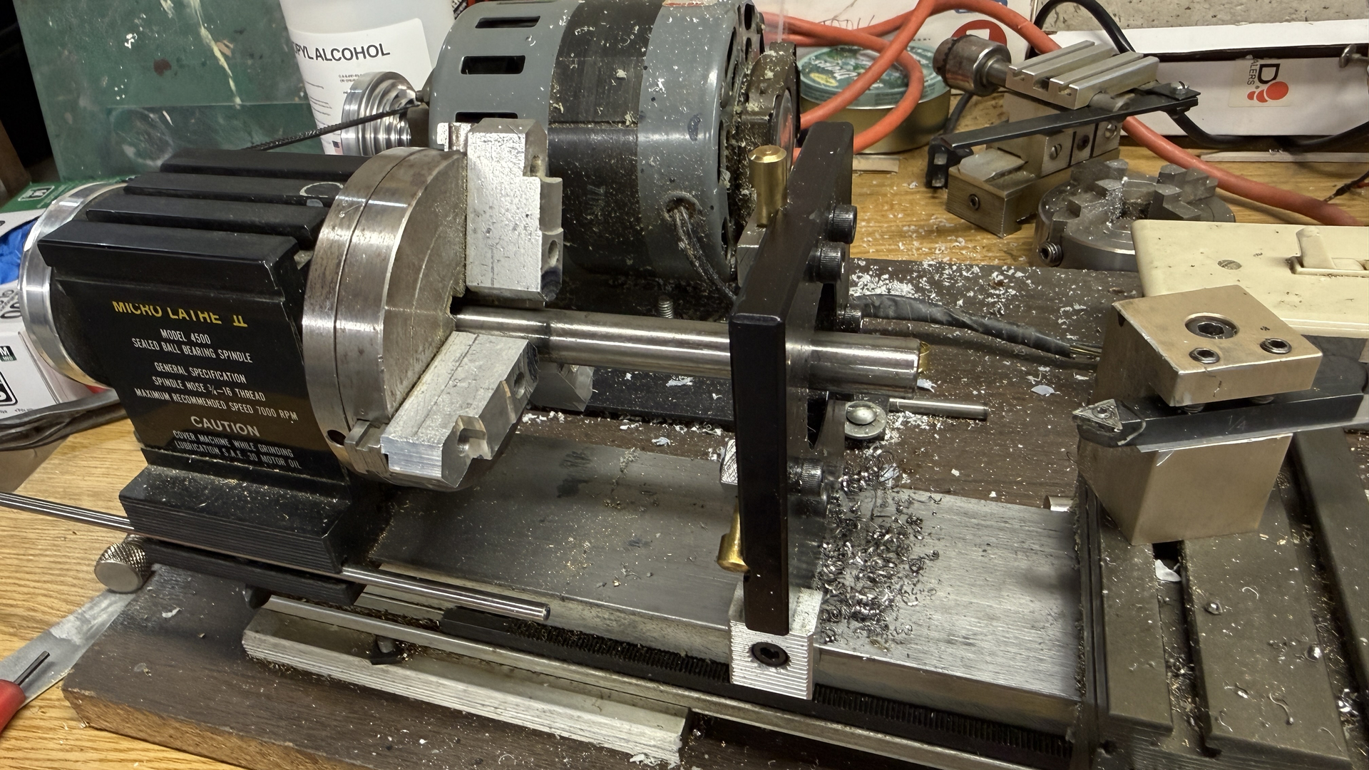
It did work. When I did the first piece, I creeped up on the final i.d., but found that if I left the boring bar at the same position, carefully re-chucking each piece in the same orientation and slowly feeding the bar into the bore, I was able to get the finished i.d. in one cut. I repeated this for the remaining cylinders.

Here’s a movie showing the cut being made. The feed had to be very slow, otherwise, the tool would dig in an either rip it out of the chuck or disintegrate it. I’m having trouble getting this movie to run on YouTube. See if it works better for you…

The brass tubing cylinder liners are a slip fit. This is okay since I’m going to secure them with epoxy. The cylinder walls aren’t that thick and a press fit would have invited big trouble.

The ram is going to slide nicely. I will add some very nice grease to make it slider even better.

The foundation print was okay, but had some weird areas that were porous and spongy. Never saw that before. Using the part fails or doesn’t. It doesn’t decompose. I filled all the areas as best as I could with Bondic and it will be okay. The areas are not easily visible.

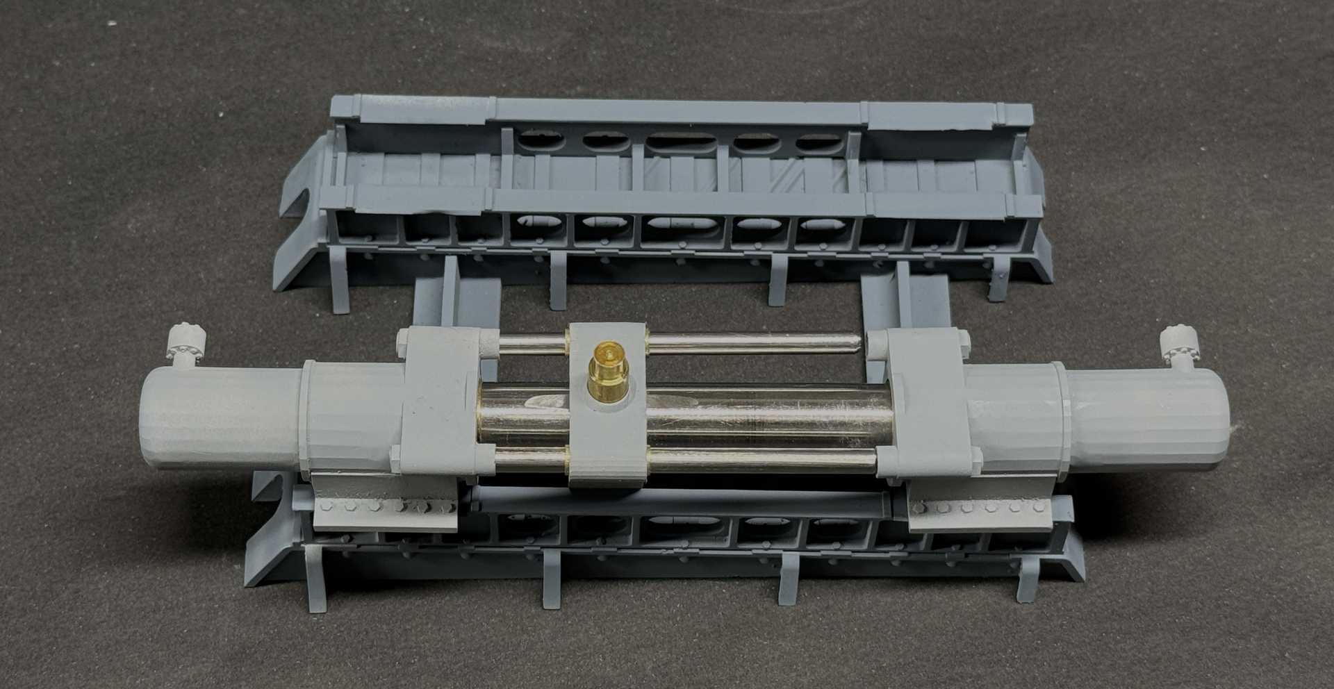
I placed the cylinders in their respective positions to show how they will be fixed.

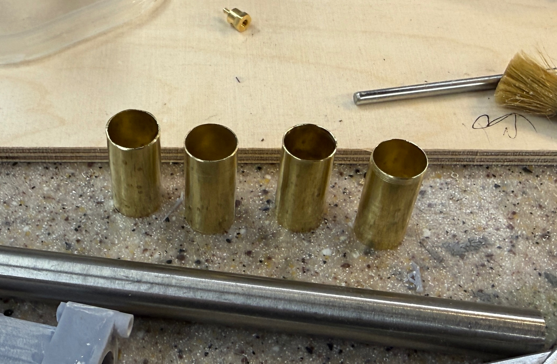
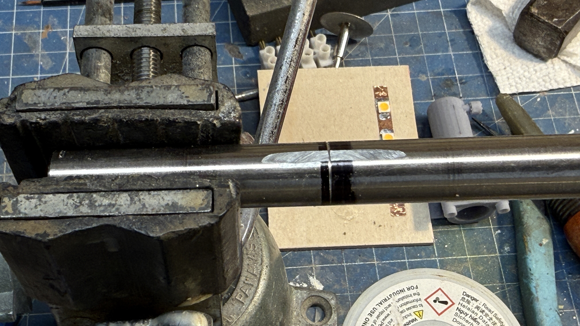
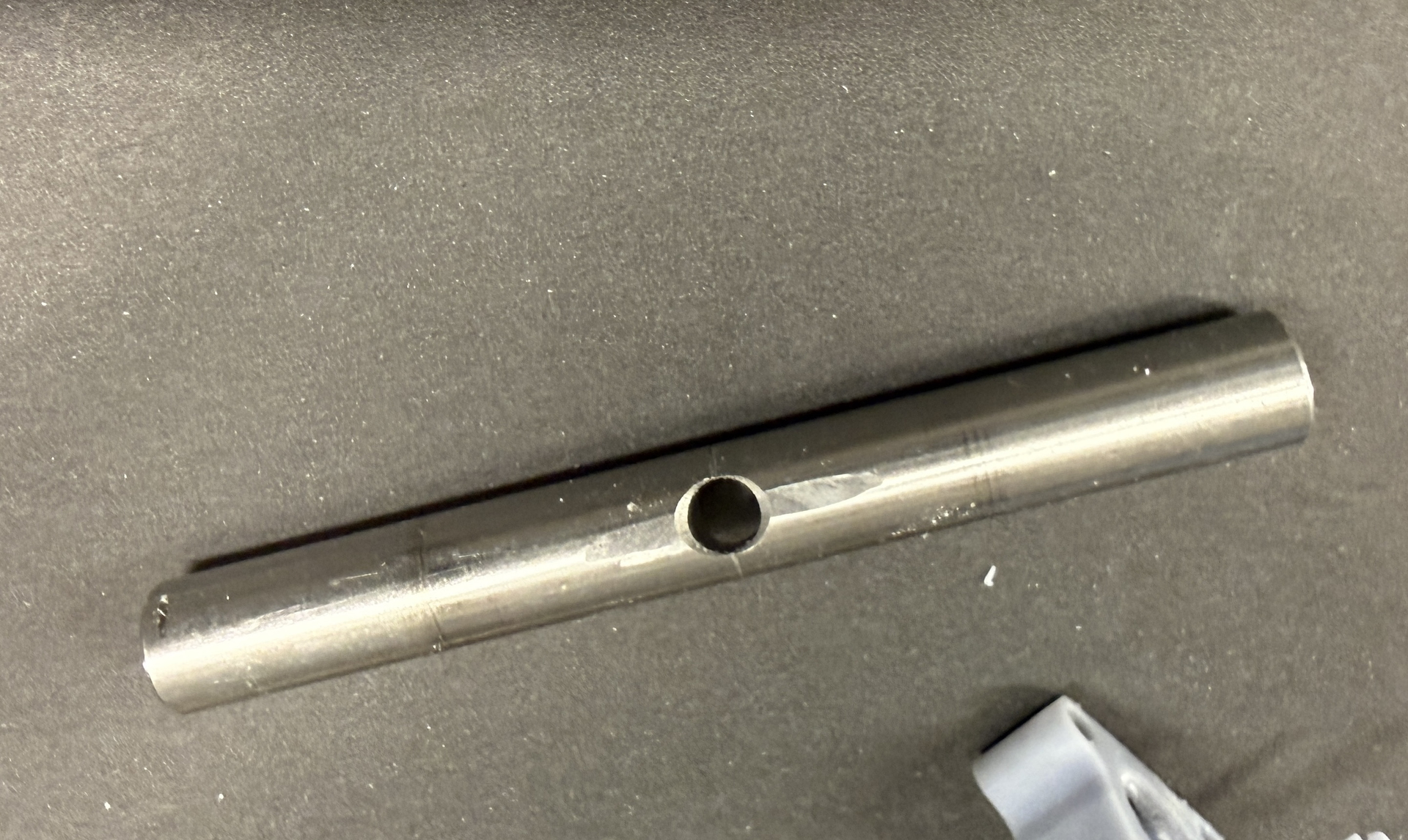
Last thing I did was cut the four cylinder bearing liners. Cutting thin wall tubing is difficult. My mini-cutoff saw’s abrasive wheel has been wearing so the diameter is no longer able to cut more than about 1/4" diameter stock. MicroMark doesn’t seem to have any in stock.

Starting tomorrow, work will stop while we take a mid-year trip back East to visit with family and friends. Work will commence after Aug 1.

4 Likes

Beautiful work, leave 'em wanting more! The U-tube clip worked for me :+1: :+1: