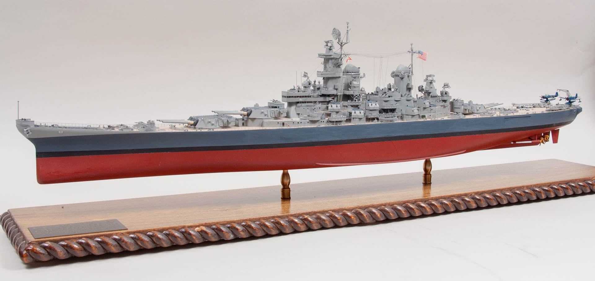
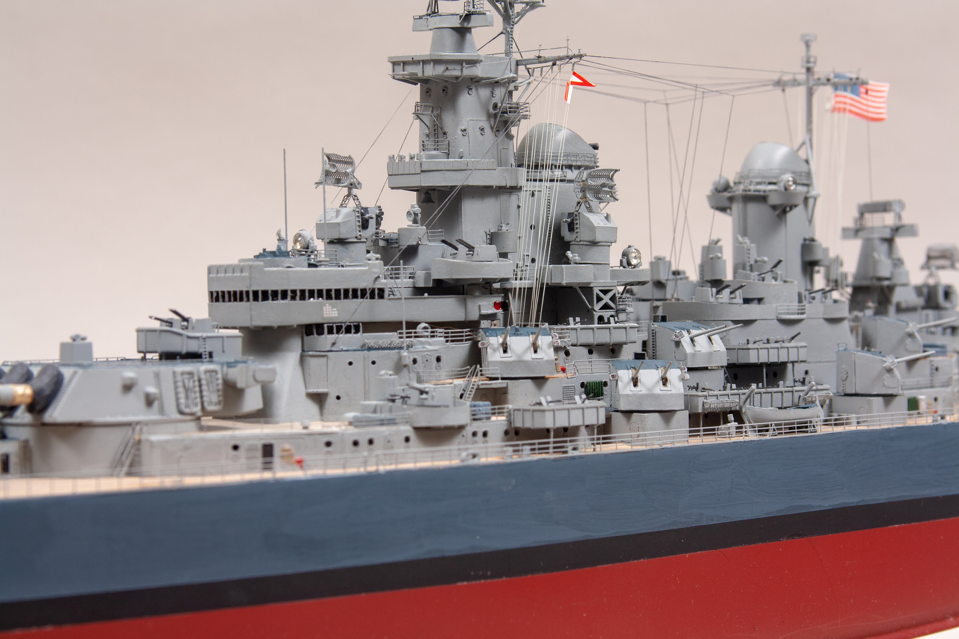
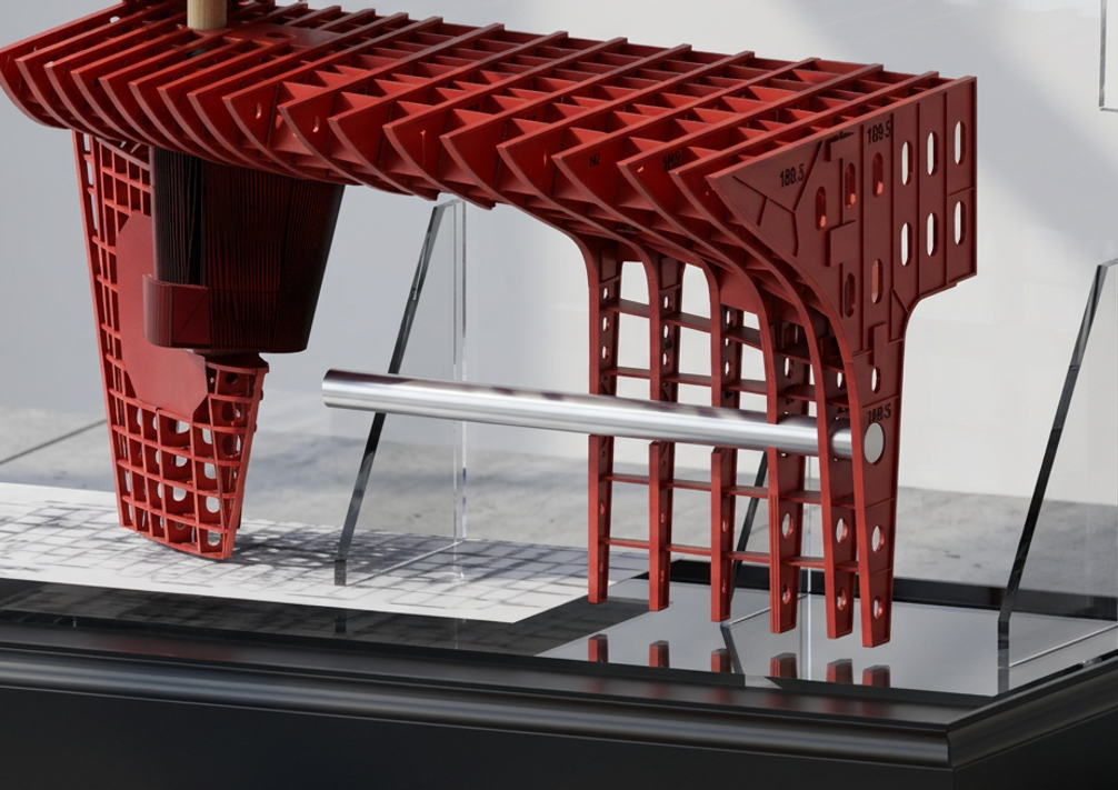
Iowa Class 1:48 Automated Steering Gear Model Start-to-Finish Build

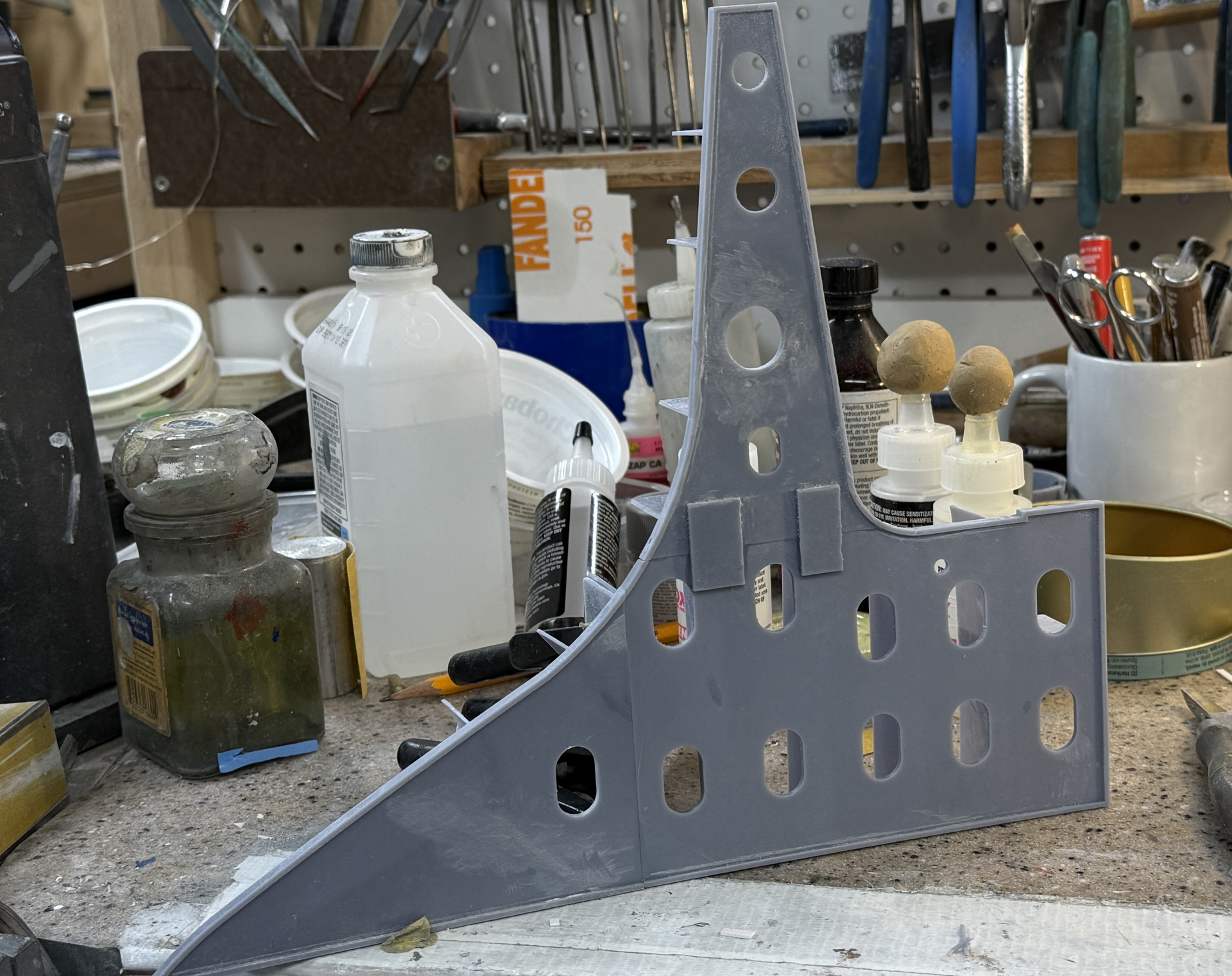
All the changes to the rudder hub are done and both halves are downloaded to the printer. It was worse thinking about it than doing it.

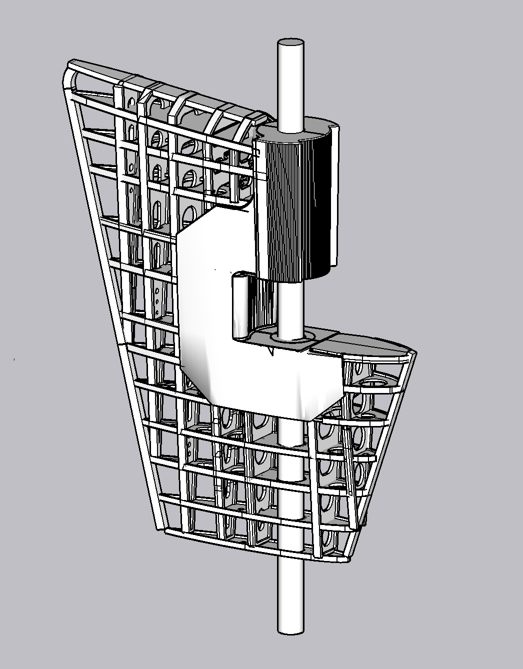
Today I did all the design and exporting of the rudder’s framing. Went smoother than expected. Split the construction into two parts to fit on the printer. The halves will key together pretty well and snuggle into the rudder forginng.

It doesn’t conform precisely to the profile drawings and not too well to John’s 3D rendering. That said, John’s 3D rendering doesn’t conform to the profile prints either, so why should I worry. It makes a respectible and BIG rudder that should work just fine.

All those non-streamline corners will be shaped after printing. All the horizontals and verticals will be blended so the skinning will provide a smooth contour. Probably going to skin with balsa. Syrene would work as well, but doesn’t glue well with CA whereas balsa glues like crazy with it. While balsa skinning isn’t that strong—without a flberglass cover layer—it’s going to be in an enclosure and shouldn’t get handled.

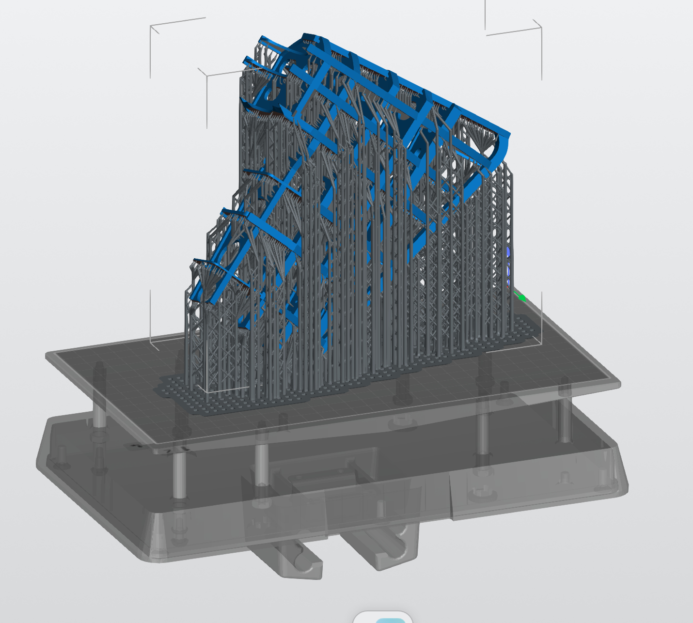
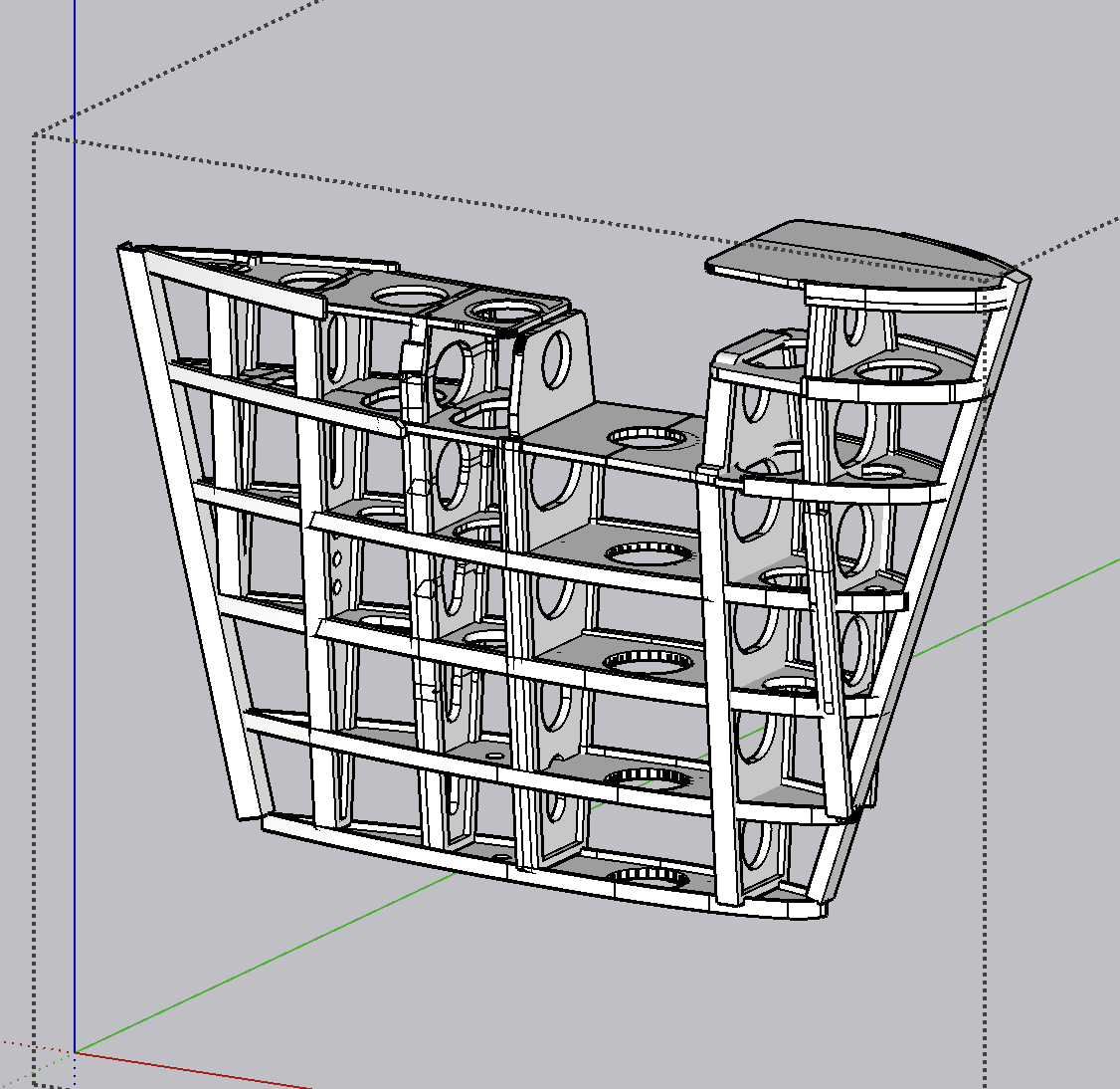
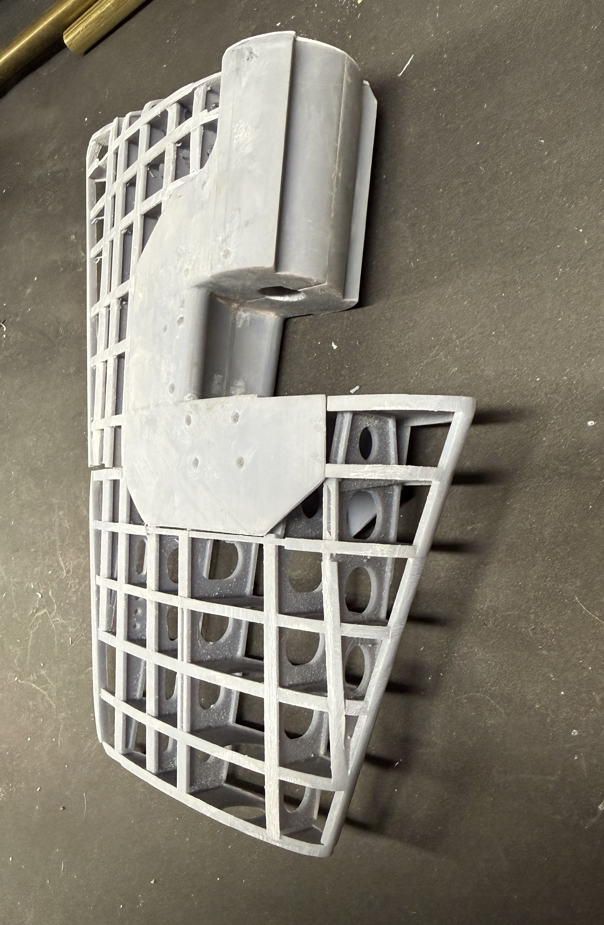
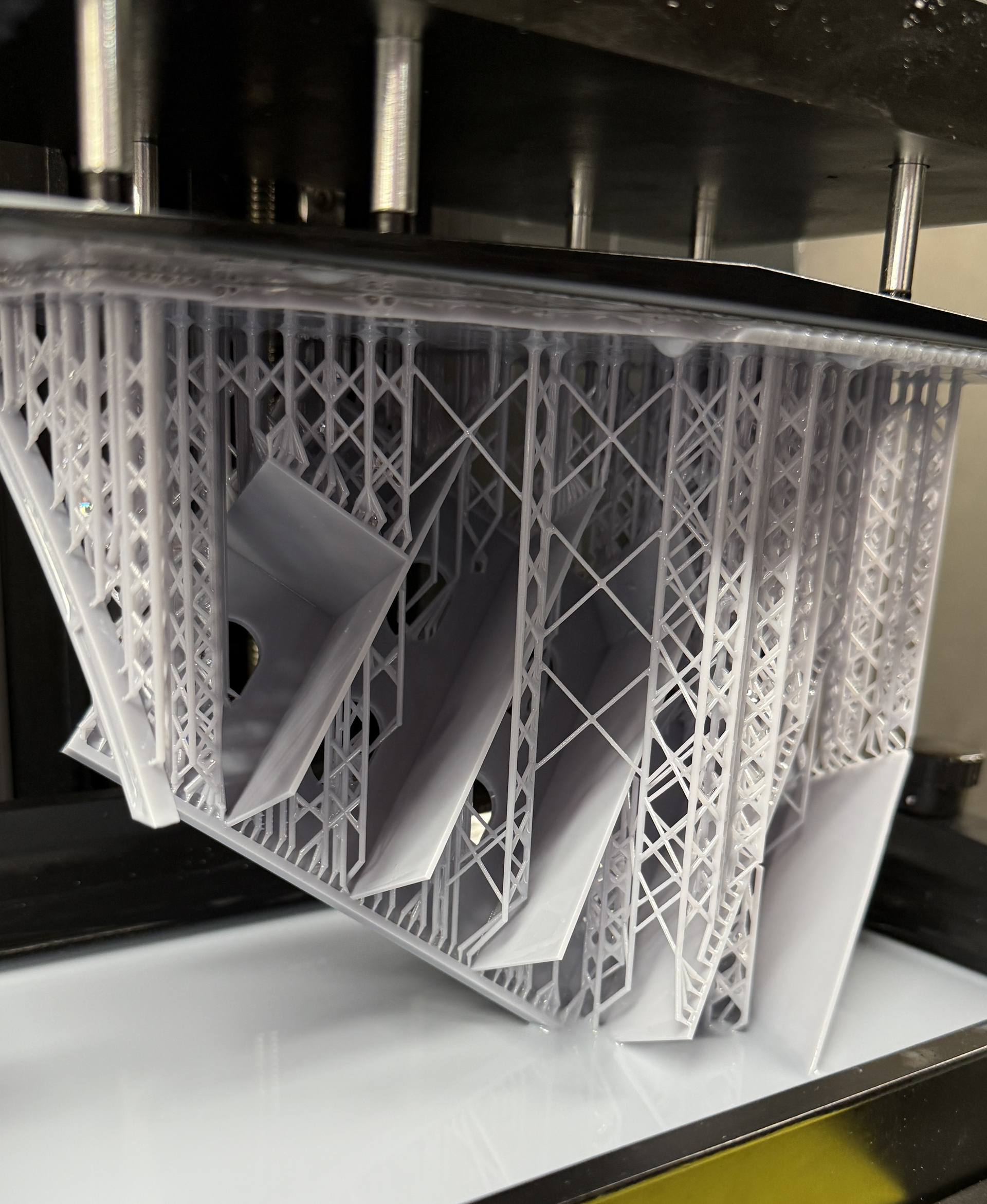
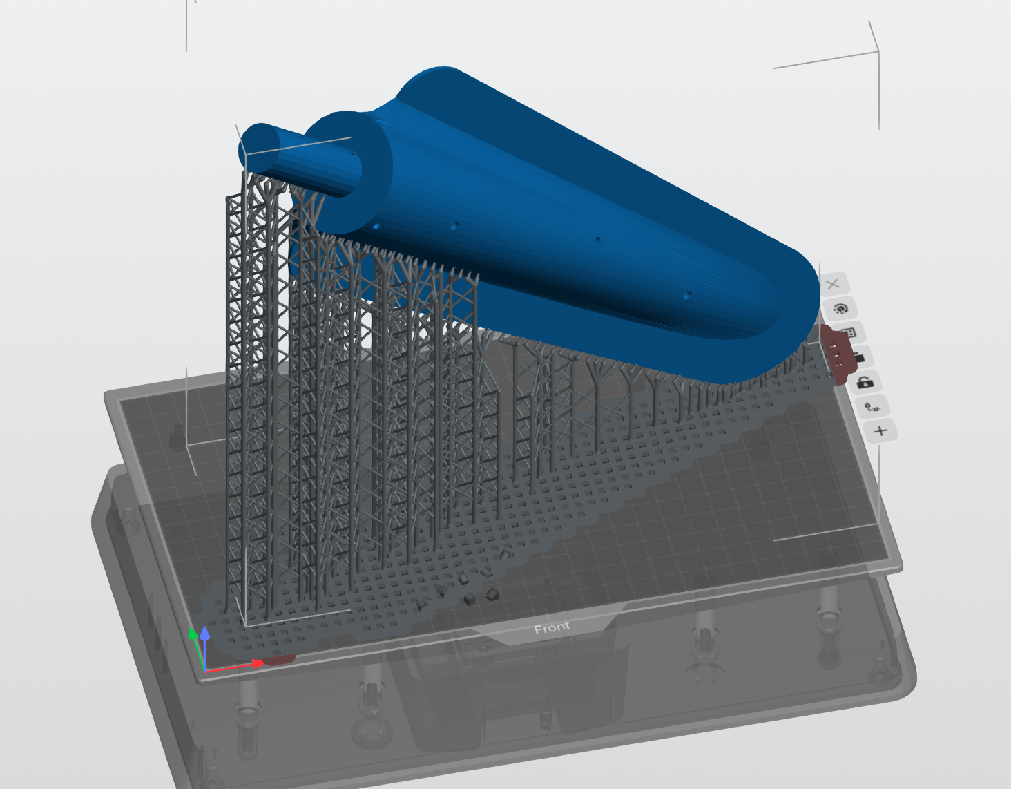
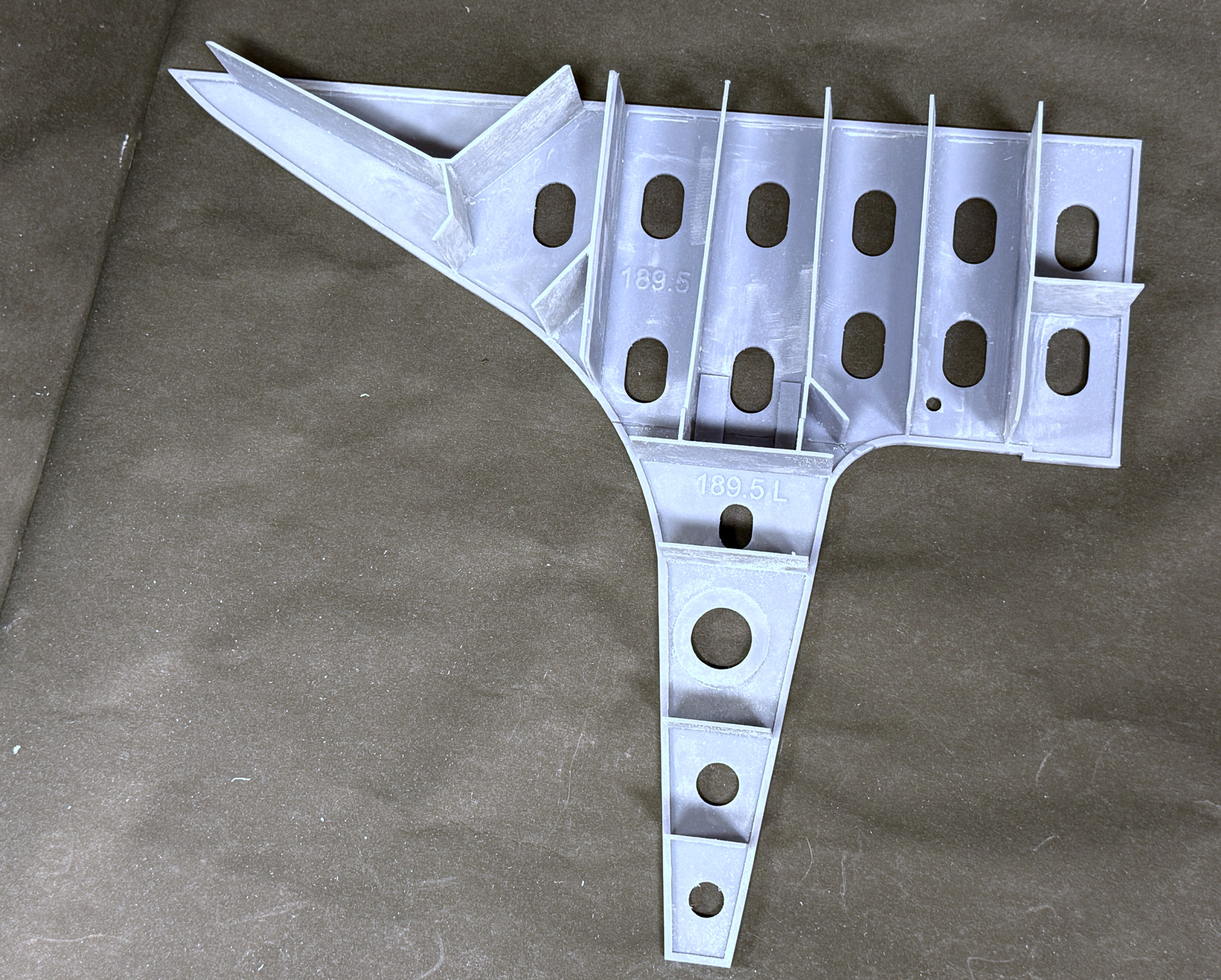
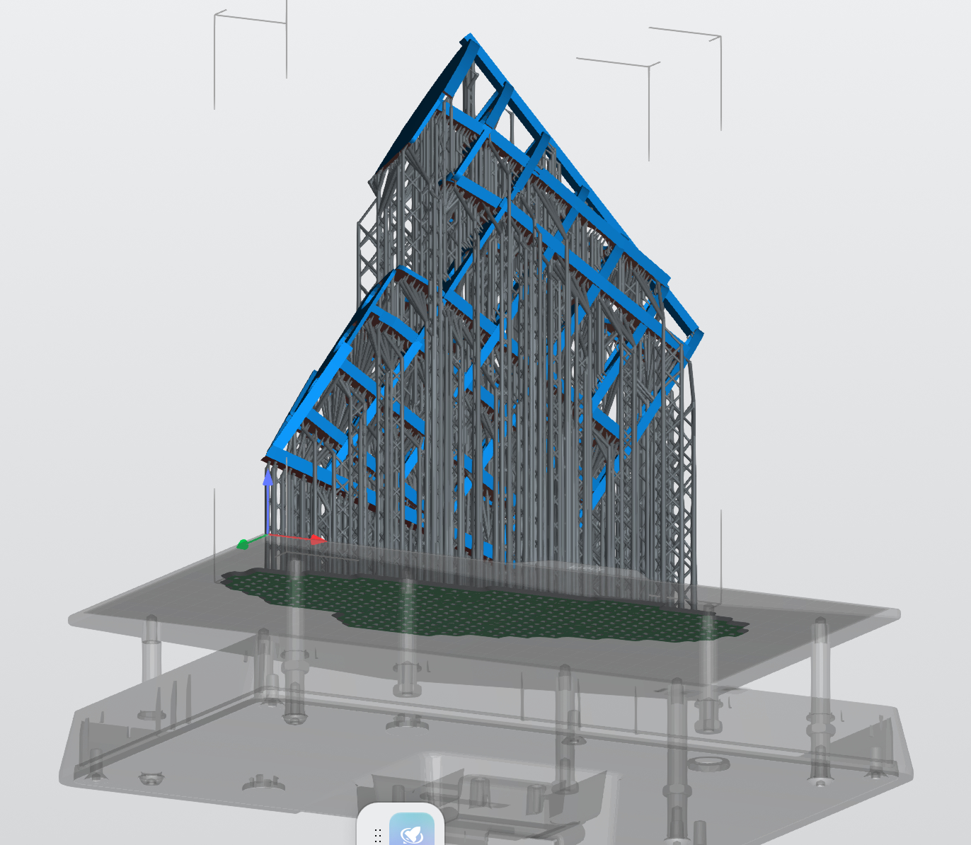
Here’s the bottom half and then as set up in the printer. The supports are a genuine forest that all must be carefully removed to reveal the part.

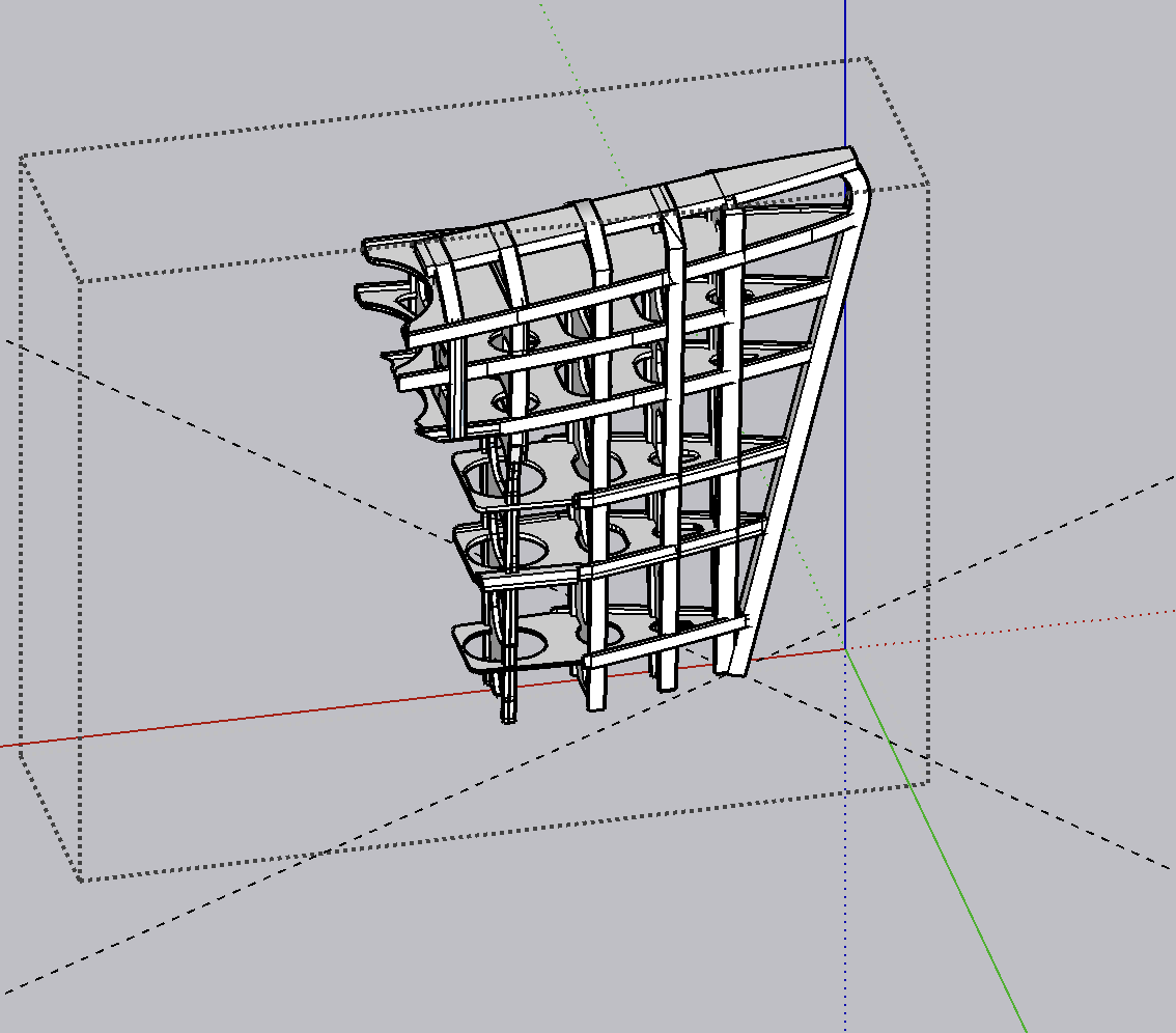
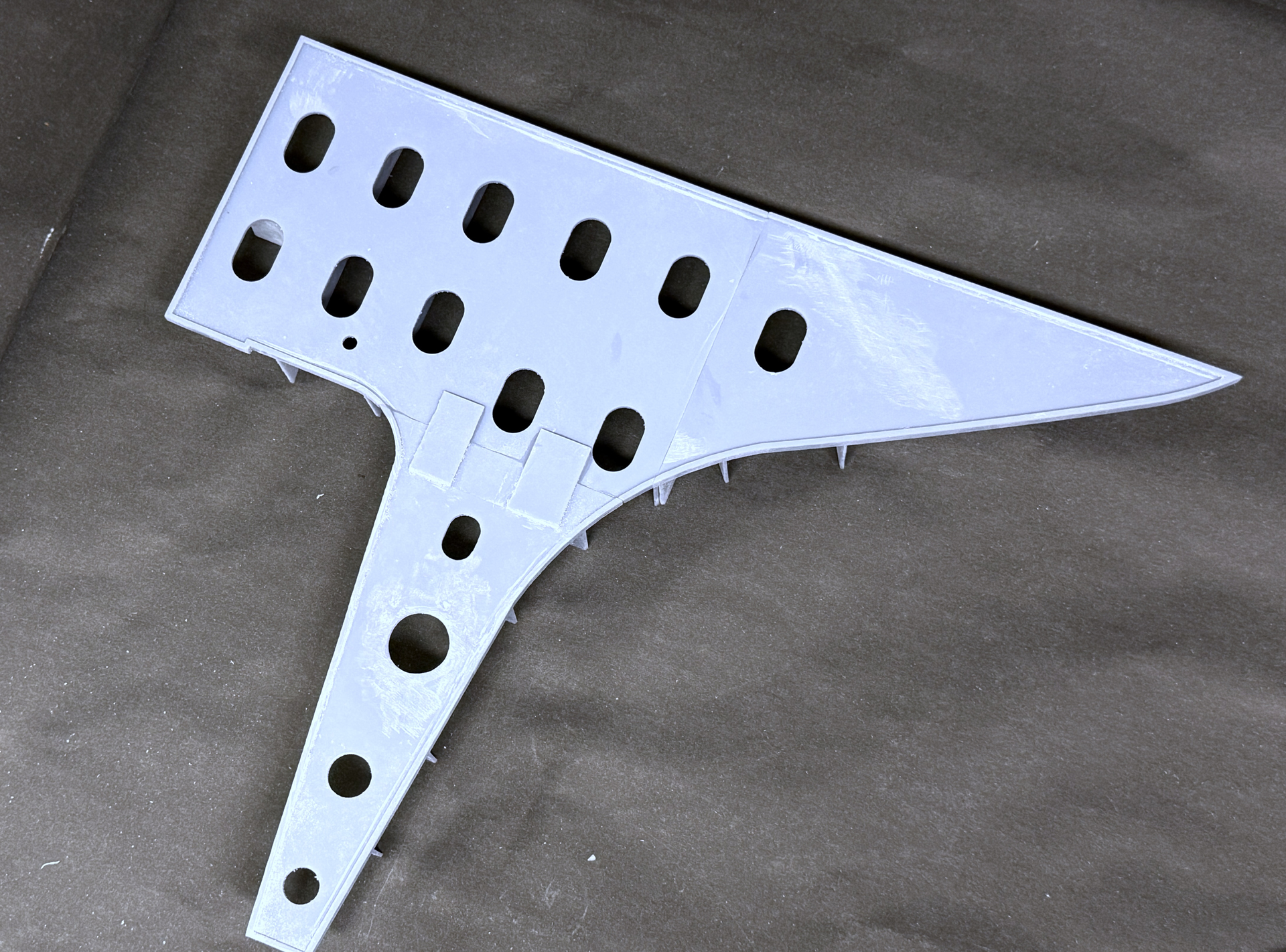
And the upper half:

These too are downloaded to the printer. It’s all waiting for some more resin to arrive from Amazon. The rudder was one of the parts of this model that gave me pause. It was complex, large, curvy and hard to visualize. My motto is “So what!” Just do something and see what happens. Stay tuned.

Latest pics not showing, Myles…

Is some kind of dry lube like graphite or Moly G a possibility? I am not a materials guy

I don’t know why the pics aren’t up. They’re showing up on my screen. Regardless, here they are again.

5 Likes

When I tried to open the pictures in a new window, it took me to a page on https://www.worldaffairsboard.com and complained that I wasn’t allowed to do that unless I was logged in, so they may have been stuck behind some anti-linking code on that site.

Builder,

Belated happy 81st.

Your work is incredible. I’m curious. And maybe you’ve told us in the past, but what is your background? Engineer? Magician? Machinist? Archimedes, Michelangelo and Rembrandt reincarnated in one body?

1 Like

Thanks JP for the birthday wishes!

Re: World Affairs Board. I post this thread on five forums. Each reaches a different audience. World Affairs Board got me started when I built my 3rd (and best) Missouri model in 2012. Wanting to replace the plastic prop shafts with metal, I wanted to know what color they were. I put the question to Google which directed me to that forum. Most of it is military/government guys talking about various topics, but I was specifically sent to the Battleship Board. On it was a guy who’s handle was “Rusty Battleship” who explained that they were white having been coated with an anti-fouling compound. And then he suggested that I blog my build on that forum. Turns out that Rusty’s real name was Dick Langraff, and he was the Long Beach Naval Shipyard superintendent during the 1980 refits of the Iowas. He knew every bolt, tank, plate on the entire ship. He and another fellow, who was a docent on the Big J, guided me to a spectacular build of that ship. I continued to blog models on there ever since. I stopped for a while because their photo upload was ridiculous. They’ve fixed all that.


Re: My Backgroud. (p.s.: you may not want to read all this following drivel, but it tells the story about why I appear to be informed about so much).
My design leanings come from wanting to be an industrial designer and going to Michigan State for that major. Wanted to design cars and this was the early 60s. As things have it, partially due to my immaturity and ADD, I got into a bit a jam with the Industrial Design Dept and had to switch majors. If you want to know more about it, we should take it off line.

This was first term junior year so I already had a lot of $$$ invested as a full-tuition out-of-state student, and I was the founder of a fabulous R & B band that was doing great. So I had to pick a different major. Viet Nam was raging and I lost my student deferment and went for a draft physical in Detroit and passed.

I had a terrific major in high school; industrial arts college prep. I had all the shops and all the academics for college. It was a “pre-engineering” curriculum. My MSU advisor looked at my high school transcript and suggested that “Since I did so well in shop class, did I ever consider being a shop teacher?” I thought she had lost her mind! I didn’t like school that much and teaching was literally the last profession that I ever considered.

She suggested that I talk with Dr. McClean, the dept head, and see what’s what. Dr. McClean was a wonderful man! He laid out what shop teaching entailed and how it can help kids. I switched majors, and my miserable grade point went up from like a 2.2 to 3.5 gpa. I had forgotten just how much I loved working with my hands. I graduated and had a job teaching inner city middle school shop. At that time, there was a shortage of teachers willing to work in under-serviced city neighborhoods and as an incentive gave an occupational deferment. I was married three weeks after graduation to the Philly girl I was dating, long-distance, through my college years.

I taught public school industrial arts for seven years. The first 3 months replacing a long-term substitute metal shop teacher. Then I was offered the first Power Technology position in Philadelphia. I taught power tech for three years during which time I earned my Masters Degree at Temple University. I then moved to the suburbs for more pay and taught Power Tech AND Metal Shop in two different rooms.

Having to master both of these subjects already was making me somewhat of a Renaissance Man. As a married man with a mortgage and baby, teaching salary was not enough and I worked six hours after school running a lathe in a machine shop.

In 1975, I had the opportunity to teach a night ship class to production workers a world-leading maker of industrial instrumentation. During my plant visit and interview I asked “what’s going to happen a the end of this 10-week drill press course?” The answer was, “We never did anything like this before. If the program succeeds you have a blank check.” On the drive home, I envisioned running the training function in two years. My wife thought I was nuts. “You’re quitting a $4.00/hr job that has no defined end, for a $10/hr job that last 10 weeks.” I convinced her of my vision and was the head of the technical training center in two years. That covered both in house skills training and customer maintenance courses. And I now knew a whole lot about instruemtation to the point of writing articles about it in techncial publications.

One job led to another. Got a job at ARCO Chemical, first in technical training and then graduating to management training. The trouble with being a trainer is that every time the business cycle slumps you get laid off based on the erroneous belief that “We’re not hiring so we don’t need training.” After ARCO was Engelhard, where I moved from training manager to training director and leaned about catalyst, precious metal refining, minerals mining.
Then came Henkel, where I was first training director for US operations and then moving to German HQ to become Chief Learning Ofc. In this capacity I ran knowledege management programs, participanted in plant studies and reengineering, executive leadership development and on and on. Due to business changes in their US operation, I was offered early retirement and returned to the States. Started my own consulting company, but the ecomony had already started to show some cracks. Then in 2005 got a job as the National Training Director for Toll Brothers, a national home builder, and learned the home building business too.

We all know what happened in 2009. Toll Brothers laid off 3/4 of their 8,000 person work force. And I retired for real, moved to Louisvile to be near the grandkids, and began to build really cool models. I’ve been reading Scientific American since I was a kid so that level of knowledge is piled on all the career stuff.

It’s said that a specialist is a person who knows more and more about less and less until he/she knows everything about nothing, And conversely, a generalist is a person who knows less and less about more and more until he knows nothing about everything. I’m heading in the latter direction.

They also say, when a person dies, a library dies with them. Part of the reason I blog all this stuff is to spread my knowledge about the things I do to others before I die.
6 Likes

Ryan Sizmanski wondered why the rudder was so fabricated. i suggested that it was to reduce weight. While this seems to be a non-issue with somthing that already weighed 47,000t empty, it really is a concern. Every ton of extra weight means less armor and less magazine stores. It’s already drawing 36’ feet of water. And a lighter rudder would have faster helm response. It’s hard enough to turn a 25’ high slab of steel into a water flow generated by a 57t ship moving at 33 knots, you don’t need that slab to be overweight.

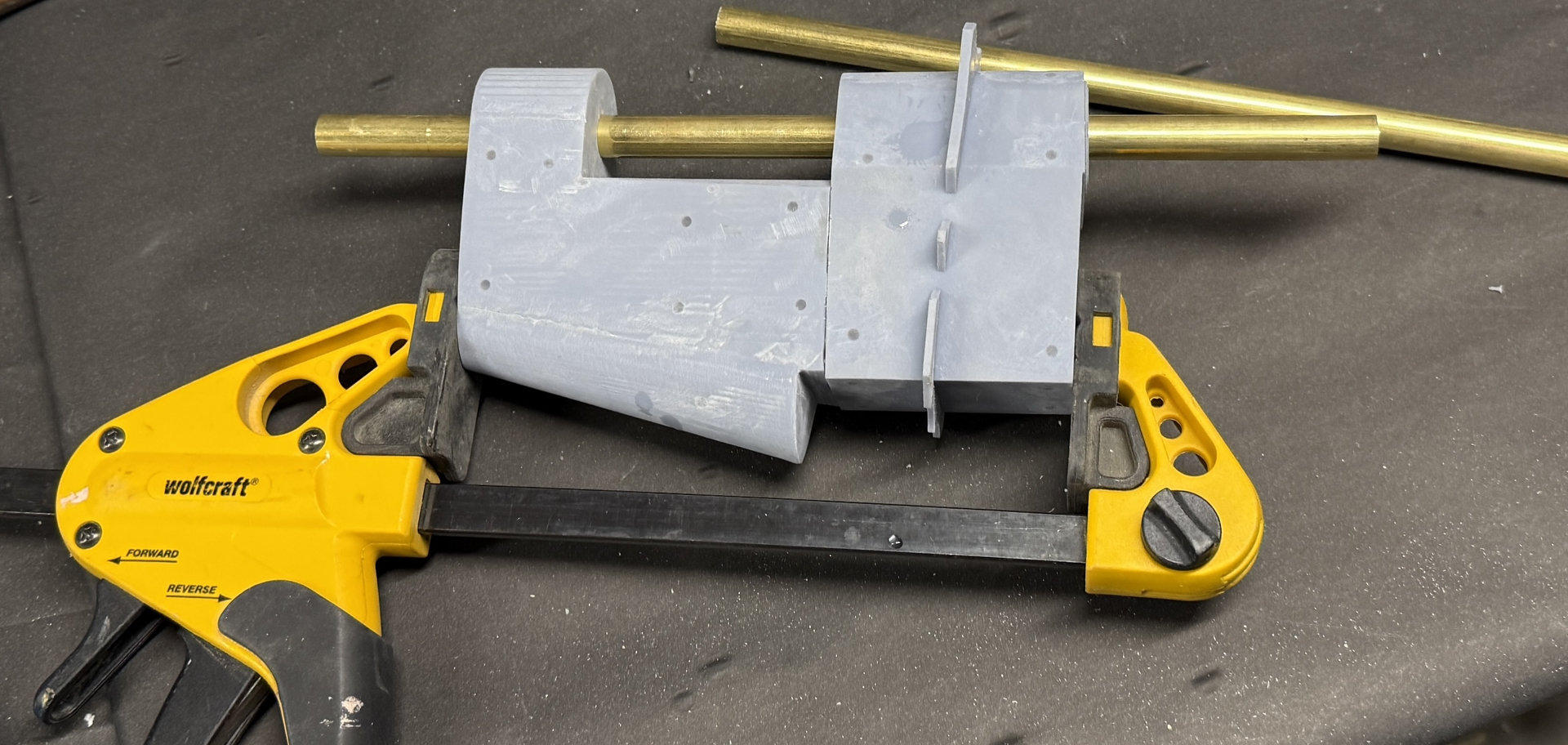
As to the model, it also meant I could build them in two parts. First, so it would fit on my printer, but secondly, as a single component, there would be no way to assemble it with the single-piece rudder forging.

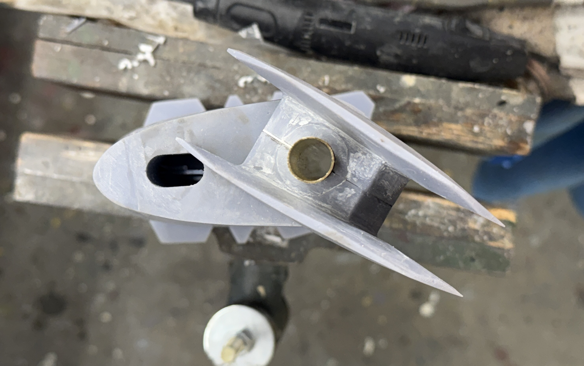
I got the new rudder hub glued together last night, and, with a little relieving here and there, got the rudder to smoothly turn 35º in each direction. The SINGLE weld flange is now correctly located. There was a pinhole in the model that was weeping some uncured resin. I sealed it with Bondic.

There is a positive stop built into the hub that prevents going beyond that limit.

The latest version of ChiTuBox places supports everywhere they’re needed, even in recesses and places that are not visible. Past versions would only place supports where they had a direct connection down to the build plate, and in many cases wouldn’t let you place supports from one part of the model to another. That said, it results in hundreds of supports on a part this complex. Removable was slow, but steady. You have to be careful not to remove actual part when manhandling the supports. For the frames I used all medium supports with heavies only on the bottom most portion to the build plate to ensure that the base connection is strong.

This was when half of the supports were removed.

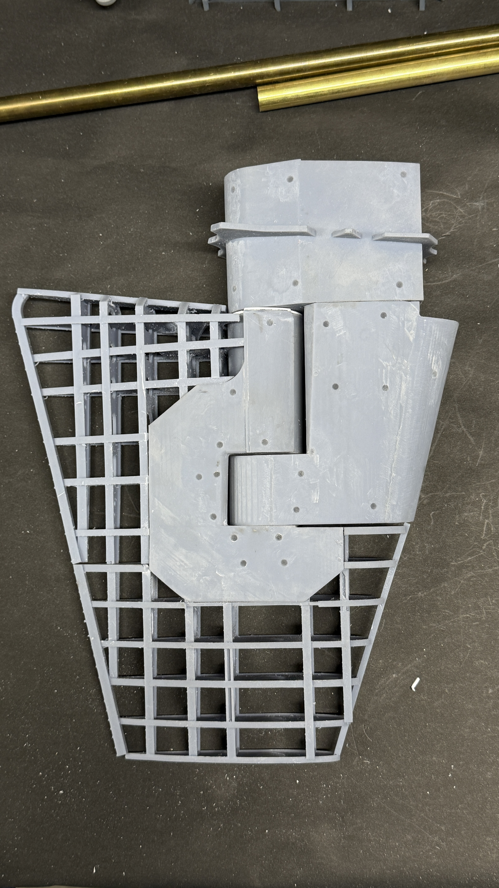
I had to remove some stock where the frames entered the confines of the rudder forging. I was expecting this since I used “Interface Surfaces” to locate the interacting contact points and knew that it would be an interference fit. After several cycles of fit/sand/fit, I got the frames to nestle into position.

I then, working slowly and carefully on the 1" belt sander, removed the high spots on the stringers and faired the leading and trailing edges into the frame.

This pic is before any surface sanding.

And lastly, here’s an oblique view showing the sanding.

This whole part of the job came out much easier than I envisioned. When I saw John’s rendering and how complex it was I ran through several scenarios. One was to make the ribs separately and use strip stringers to tie them together a la model airplane construction. But it meant that the web frames had to be individual pieces needing gluing and fitting. They simply couldn’t pass through each other as seen on SketchUp. But, once I drew them all together with the stringers, the printer didn’t care.

Next up is skinning. I can use styrene or balsa. Styrene has a better surface, but isn’t really good to glue with CA or even epoxy, and solvent cements don’t work on resin. Balsa glues well with both, but requires tons of filling and finishing to give it a metal-like finish. I have enough styrene in the shop. I’ll go this route, using epoxy and small screws to hold the plates in place until it cures and then fill the screw holes aftwards. Any thoughts?

5 Likes

Fantastic build Myles – a 3rd candidate for skinning might be one of several grades of metal foil. I won’t sully your thread with my usage, but the grade used for foil baking trays could be worth experimenting with. A slightly lighter Goldilocks grade I like to use is the foil seal in the 500g tins of Nescafe. As for adhesion, it tolerates epoxy & CA to styrene, never tried it to resin though.

Tim, the real rudder is covered in something so thick that none of the framing contours are visible on the surface. I don’t have the specs, but I would assume that the plate thickness is an inch (25.4mm) or more. That’s 0.030" in 1:32. I suspect that it’s thicker than that. I have one framing plan and it gives plate thicknesses in pounds. I don’t have a rudder skinning plan. I’m assuming that’s the weight of the steel in a square foot, just like railroad rail is pounds per linear foot. I have 0.040" styrene and would use 1/16" balsa. It’s not really an airplane wing… it just looks like one. Think of the pounding the rudder takes in service…

BTW: John Miano has framing plans for the sections of the ship that I need. I’m going to try and replicate as much of the surrounding structure as I can and his plans will be perfect. I just sent him a DropBox file request for him to transfer the files to me.

1 Like

Today, three things happened. Two good and one meh.

I finished cleaning up the rudder frame halves, added some styrene strips to level out some dips in the frame, and then epoxied the three parts together after getting the fit as good as I could get it. There’s a divot in the trailing edge that I’ll fix before painting on Monday.

I had a plan to enlarge the 13mm holes in the rudder bearing to accept the 17/32 brass tube to serve as a better bearing in the existing hole. I had to order a 29/64 drill to do the job. The drill was UPS’d to a local dropoff point at a Michael’s Crafts store. I had to go three days in a row for them to finally find it.

The drill just barely fit my drill press. It was almost a push fit into the chuck. Then I had to loosen the drill press head to revolve it so it would hang over the table edge to fit the entire rudder bearing under it. Holding the part with Channellocks, I attempted to enlarge the hole. Even with removing the sharp leading edge on the drill, it kept grabbing. It also was overloading the small drill press’ power and old belt kept slipping. I did get the holes deep enough on each side to slip in the bushing on the ends. But they weren’t perfectly in line and the shaft spun no smoother than without them. The experiment was deemed a failure and I wasted money on a drill that I will never ever use again. Because I ground off the leading edge, I can’t return it.

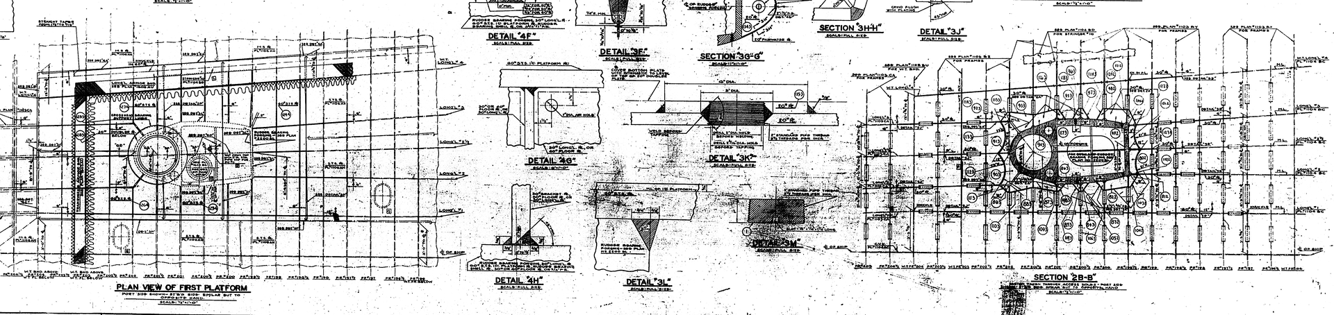
Lastly, John Miano sent me the entire set of Big J framing elevation drawings covering the entire aft section including the steering gear. Plus a plan view of all the complex framing that traps the rudder bearing into the ship’s structure. This stuff is priceless! I can now make the ship hull structiure as detailed (or not) that I wish, not constrained by lack of information.

Here’s an example.

This is so much fun!!

Have a wonderful weekend. If you’re Jewish, have a good fast and best wishes for a healthy and happy new year.

5 Likes

After getting the framing drawings from John Miano, I got down to business drawing them in 3D. The first thing I noticed was their quality. Not good. I could barely make out any text, but just enough to make out a few dimensions that I could use for scaling. That brings up the second challenge. I would scale the drawing to a specific measure, for example: 4’-O". I would draw the part. Then I find that on the other end of the sheet with another 4’ dimension, it measured 3’-9". I found out from John that the microfilm transcription sometimes warps the microfilm. I then had to individually scale each frame on the sheet to ensure that they’re based on the same scale.

Lastly there was a 3rd challenge. The 1:32 scale frames came out to over 11" wide. No material what I did, that sized part will not fit on my machine. I then started working on Plan B; sending scaled 2D profiles to CorelDraw and drawing them for auto-scribing the shapes on the digital vinyl cutter. This would have taken a ton of time. Then when visiting the shop this morning, I realized I could break down each frame into parts to fit the printer. That is what I’m doing.

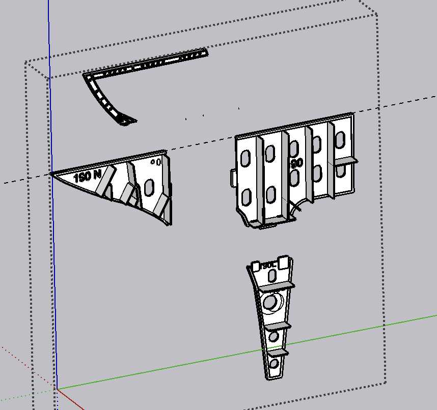
You will notice that the parts of the longitudinal members are included in the drawing and being printed with them. This serves two purposed: it automatically sets the frame spacing for assembly and ensures that all these pieces are shaped and positioned properly. In communications with John he explained that the longitudinal are installed in long sheets and it’s the frames that are welded in pieces to them. I conceived it in reverse. Actually, to build the model prototypically would have been much more difficult.

I can get two frame parts of the four onto the printer and this image shows the job almost complete.

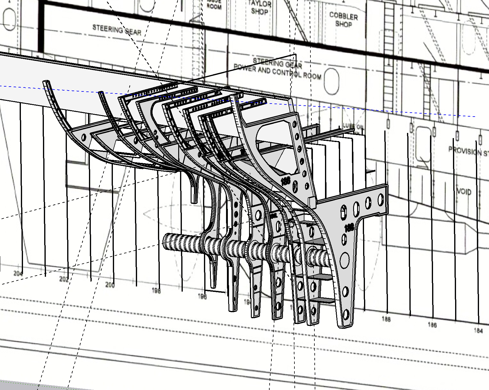
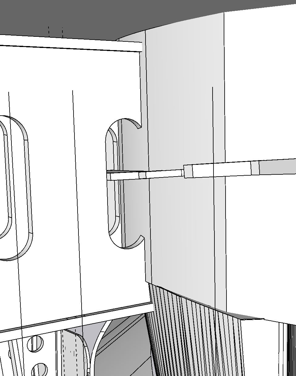
Lastly, here’s the progress so far. If you’re paying attention, you will note that the frames are not lining up vertically with the section diagram of the ship. They are situated much lower. Turns out that this diagram, that I have been using for lots of New Jersey projects, is not correct. It’s an illustration, not a blue print. I know that the frames are correct since they are drawn from builder’s plans.

The plans have the bulges on the sides of the skeg portion. The plans call this the “Twin Keel”. Actually, those bulges on the ship are the massive prop fairing casting which I’m printing separately. So everywhere I drew them according to the plan, I’m removing while editing each frame for printing.

This project is starting to cost some $$$. I have to buy heavy 1/4 plexiglass to make the support, case and base materials, and sheet styrene for the skinning of all the parts.

6 Likes

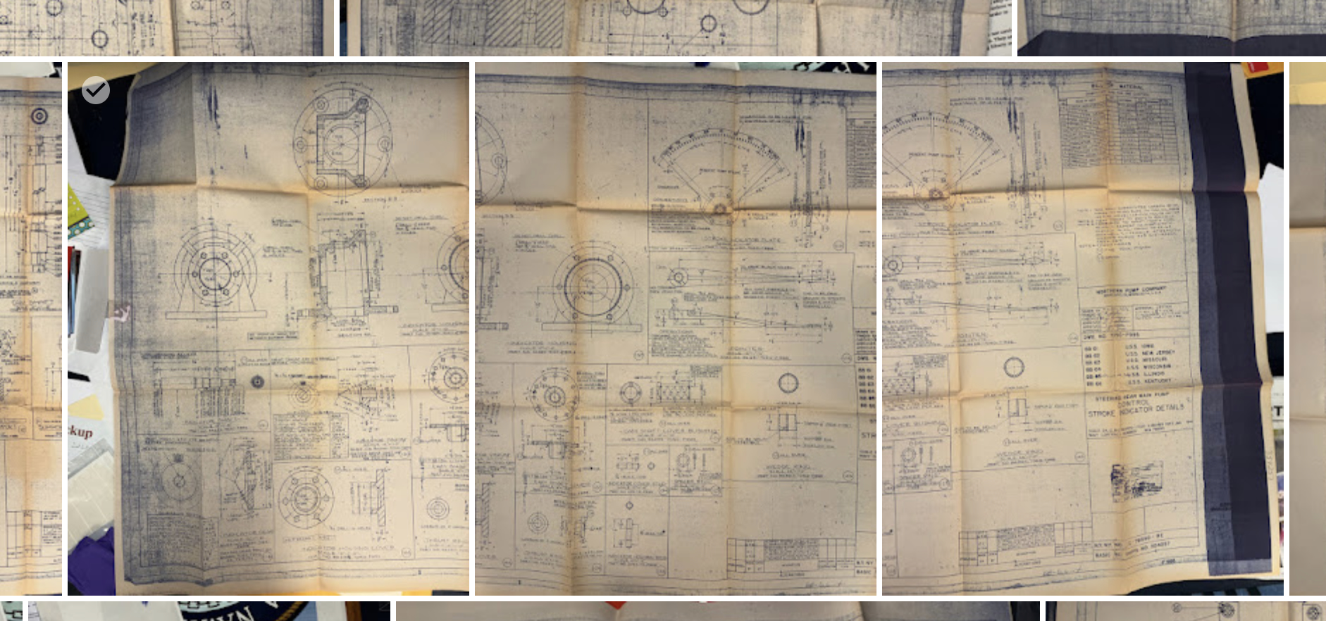
I’m figuring all this out as I go. With each new piece of puzzle I have to reconsider what I’m doing. On Friday, Ryan sent me 99 images representing many of the drawings of the hydraulics section. Due to the width of these original blueprints (held in the ship’s “Blueprint Room” next to Ryan’s office) he had to take multiple exposures of each on. There’s actually around 25 actual drawings involved.

For them to be usable I had to import them and then… hopefully…clean them up so I can read and trace over top of the them.

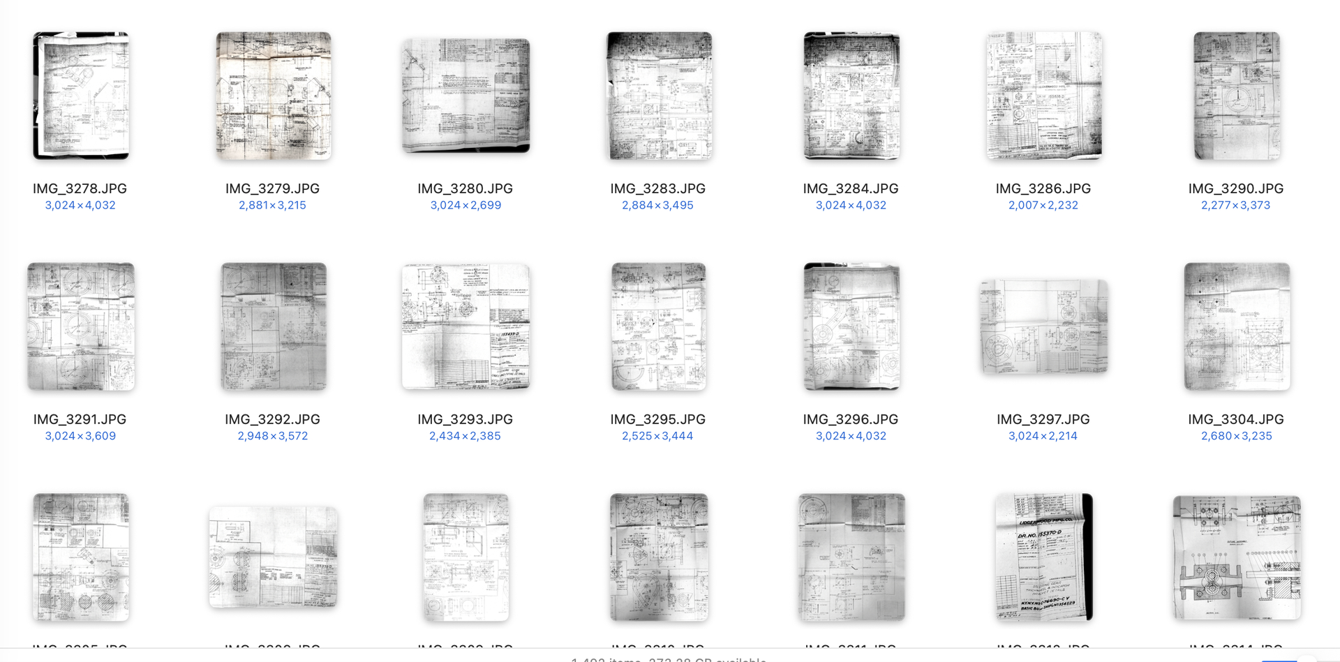
This is what it looks llke in my file directory. This is not all of them.

Many have details that I don’t need like specific designs of gear boxes, etc., but reading them all is interesting in its own right. For example: the Navy calls the massive hydraulic rams “Servos”. I suppose they do what a servo does, but that would mean all hydraulic actuators are “servos.” It also have the actual pipe runs for ALL the piping including the critical high pressure lines. They’re interesting too. There’s one pipe that goes to the starboard fore cylinder and the port aft, and another that does the opposite. There are T’s that carry the fluid to the first end and then to the other. This means the opposing ends get exactly the same flow giving the push-pull force needed. And there’s two identical pump systems in each rudder system. Only one pump is running at any time. They are switched over for maintenance and there’s a 6-way valve that controls this. There’s a whole page of plans on the control lever system that operates that valve.

I’m going to have to meld plans from the same sheets together to give me complete drawings. That won’t be easy since there’s a lot of distortion introduce by the creases in the plans. It would have been better if they were photographed under a sheet of plate glass to flatten them out. But, hey, I can’t complain.

Designing the frames has been somewhat nightmarish due to the changing of scale from one to the other. I’m redrawing all of them since I could tell there were significant errors. They weren’t lining up properly due to scale size differences between them.

The first one is complete. I used epoxy on the mating surfaces and it worked as designed.

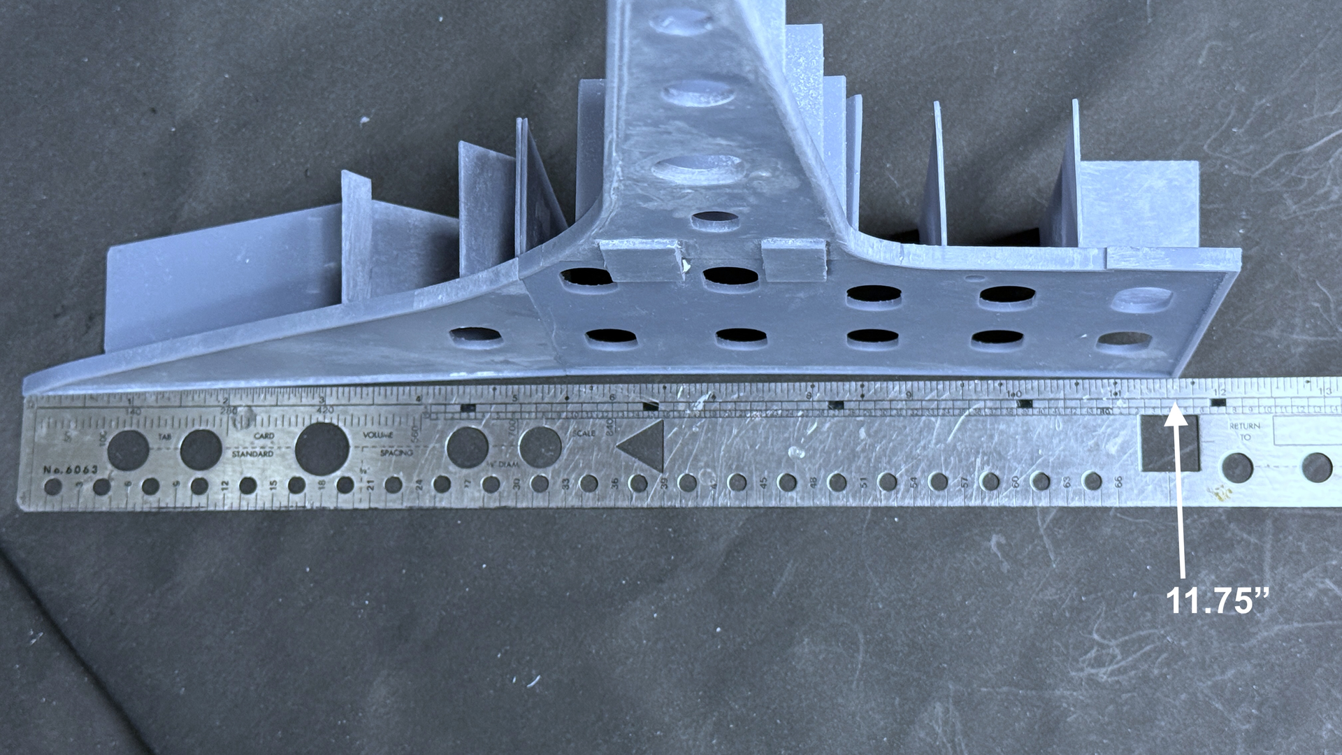
And it’s huge! Almost 12". The finished model will be about 18" wide.

The longitudinals are 3’ 9" long (scale) giving the four foot separation of the frames when you add their thicknesses.

One down and 15 more to go… Ugh!

6 Likes

A new week… new challenges. I’ve gotten 90% of the frames drawn and fit in the drawing. I’m not printing anything until I’m sure that the drawings are correct. This project is eating a lot of resin and don’t want to waste any.

The hardest part is fitting the frames around the rudder bearing. The drawings are a bit ambiguous and I had to spend a lot of time understanding them.

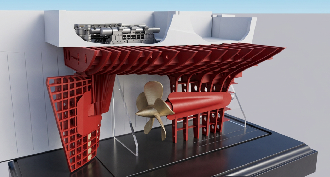
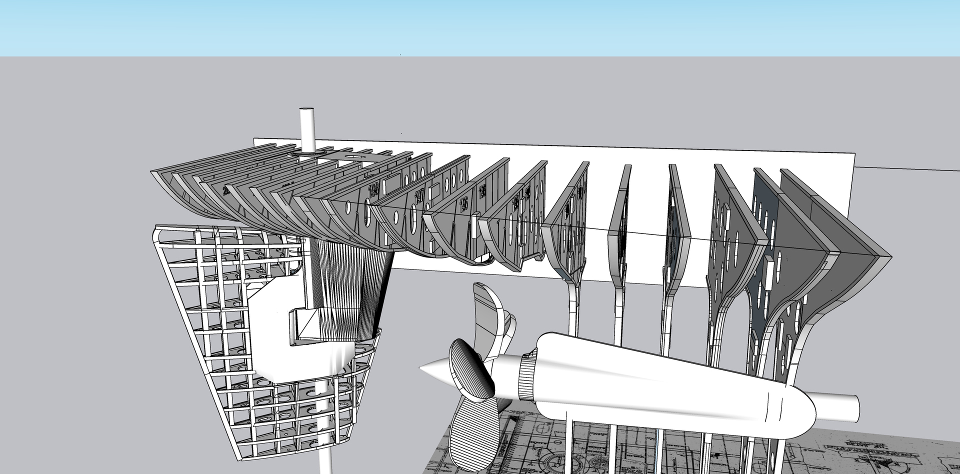
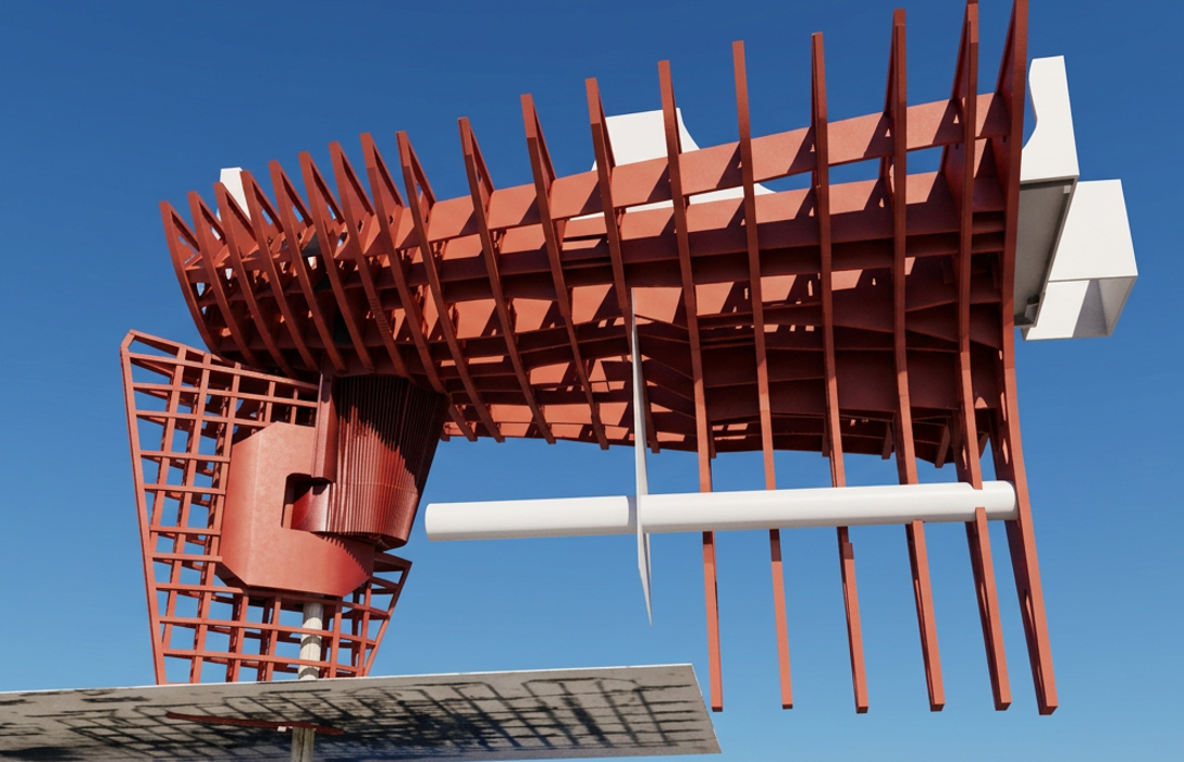
The newest interation of SketchUp has an AI rendering engine. I gave it a test run today. Produces a nice render… not as sophisticated as my VRay sub-program, but does some things well. This is what’s drawn so far. Most of the frames are broken into two or three parts, but the ones in the aft section and those wrapping around the rudder bearing don’t need all that fussing as they fit as is.

The real frames are thin plate steel with a welded this plate flange arond the perimeter and encircling each manhole. While the printer could replicate these cross-sections, their longevity would be suspect. I’ve attempted to make scale structures, but breakage becomes a major attemtion grabber. Viewers will not mind, especially with the animation and the complexity of the mechinery.

I drew the frames full and then intersected their faces with the rudder hub. Cut away all those that interfered, and closed all the open edges to make them solid again for printing. Time consuming and a bit finicky.

Here’s the AI rendering.

So dear readers, what do you think if I decided to leave the frames open as you see here? I could skin part or skin the entire thing and make some cutaway openings. Not skinning would save me some $$. Sheet styrene is expensive.

Later this week I may do some printing, but we’re taking a short trip Back East to visit family next week.

7 Likes

“Frames open” as you’ve shown in your rendering looks fantastic!

—mike :hammer_and_wrench:

5 Likes

Will the whole thing be viewable from the other side? If so I’d use a single sheet of heavy foil (heavier than tin foil) to skin just the reverse side. With very light pressure you could even press in some (or all) of the squares to create that panelled effect often seen on the real thing.

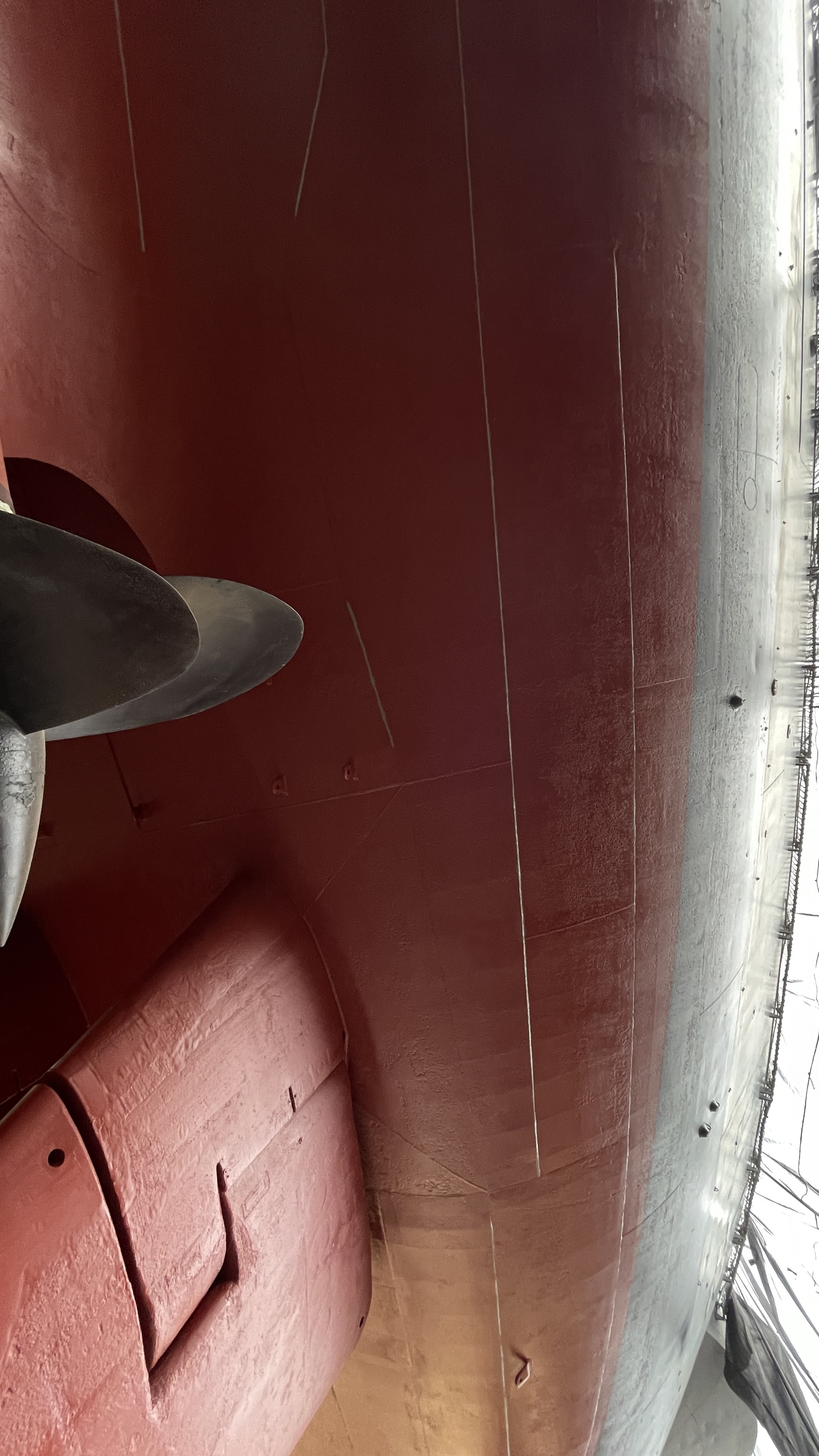
The skin at the aft is about 3/4" thick. The paneling effect only occurs near the water line where the black boot topping absorbs more heat than the gray and causes uneven expansion. This only occurs at the bows and stern. You wouldn’t see it below the water line or in places with heavier skin. Many modelers over do this effect.


Note, very little “oil canning” in these areas. In fact, the hull is remarkedly smooth considering what the shipwrights were dealing with. The skin panels are welded on their vertical seams and riveted on the horizontal overlapping ones.

The consensus is to leave it skeletal. Now that creates more work, but that’s okay.

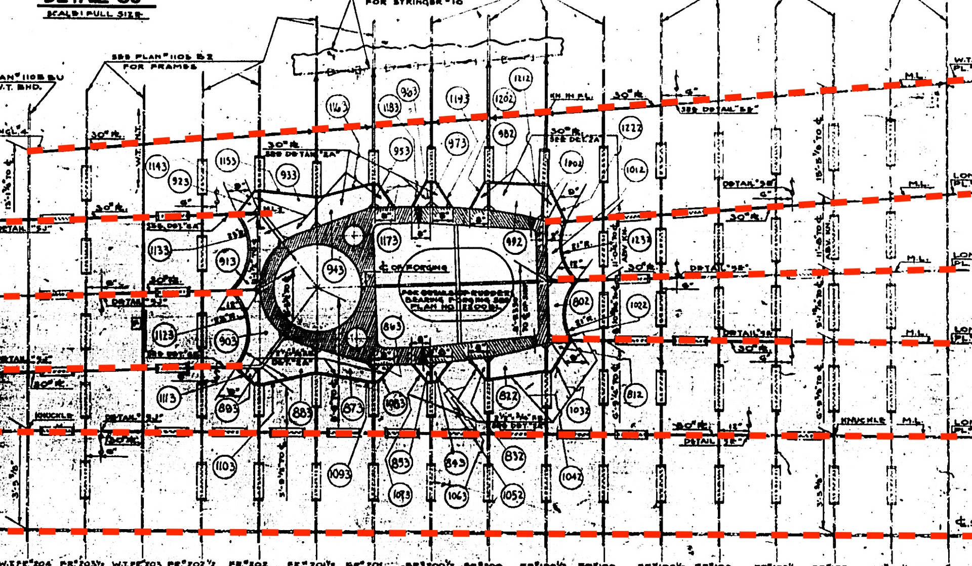
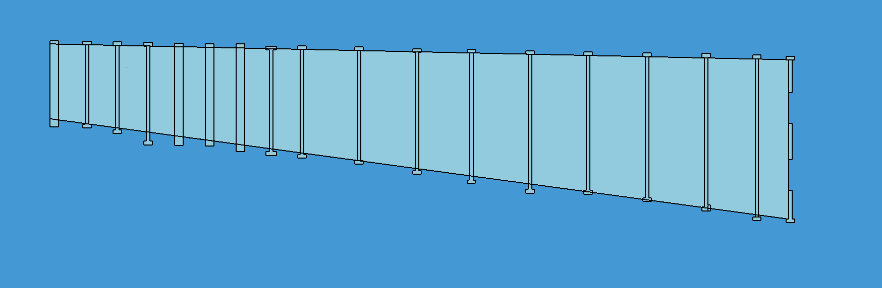
This drawing with the red, dashed lines shows the longitudinal plating that runs the length of the ship’s framing in this area. Notice that they are not parallel, but rather follow the ship’s lines. In my original design, I extruded these from the frames themselves leaving me with panels that were parallel with each other AND incorrect. Since I was planning on skinning the hull, that disrepency would have gone unnoticed. Now with it all exposed I’m compelled to fix it.

Here’s how.

I first removed all the extruded longitudinal pieces that existed at each frame. On the real ship, it was the longitudinals that were continuous plates of steel and the frames were segmented and welded to them. I can’t do it that way. I’m segmenting the longitudinals onto solid frames. To establish their sizes and locations, I’m using a solid sheet and intersecting it will all the frames at each location and at each correct angle. First, I ensured that all the frames were where I wanted them to be. I had to adjust some of their scales plus or minus a few percentage points so they would give smooth transitions from one to the next.

The intersected plate looks like this.

The next step will be to extrude the plate to thicknss since it’s now only 2D, and then separate the plates from the frame outlines, cut and paste each to the corresponding frame to which they connect. I only have to attach them to one side. By cutting and pasting IN PLACE, the plate will be sitting in perfect contact with the frame and at the correct angle. The when the frames are printed with their associated longitundinal component, they will be correct.

Stay tuned.

4 Likes

We had a nice trip back to Philly, short visit did not permit a visit to the Big J. I don’t need any more on site visits to finish the model.

It took a bit of time to use the new scheme to fit the longitudinals into the framing, but I finished that last night. They now form nice straight lines as they do on the 1:1 ship. They are not exact, but like a Monet, they give the correct “impression”.

The longitudinals are all attached to the frame on their left in the images. They will print with them. Assembling them around the rudder bearing will be tricky, but the frames are separate on the port and starboard sides and will slide into place from those directions. Even though the parts fit on the drawing, I’m anticipating a lot of filing and cutting of interferance areas.

I also have to order the heay plexiglass that will make up the support for the model. The frame will be attached to that plexiglass bracket. The local vendor I use can cut accurate pieces with a CNC router so I won’t have to worry about doing it by hand.

I’m not going to attempt to create the propeller end casting until the frame is completely done and aligned. Then I will shape the clay model to exactly fit into the space on the frame where it’s supposed to sit. Then I will scan it, finalize the drawing and print it.

5 Likes

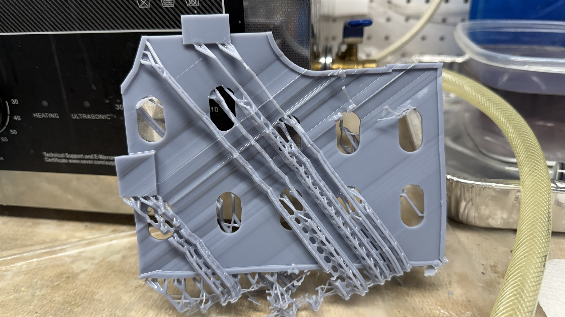
My next print job failed miserably. I thought I could get away with all medium supports except for the bottom most, but they failed. One part, the skeg portion, printed okay. The second, shown below, came out like something that goes very wrong in a Star Trek Transporter accident. And the last two ended up as large blobs on the barrier film at the vat bottom.

Something else may have been going on at the same time. When the build plate came down from the home position at the top of the x axis, it chattered badly as it approached the vat. That chatter could have caused some of the distortions you see. The cause, I am surmising, was the printer sitting idle for weeks and the slide lube might have been drying out. I lubricated the slides and lead screw and exercised the axis many times through the binding portion until it smoothed out.

The next print, finished and draining in the machine, came out flawlessly. I changed the support scheme to all heavies. Don’t know which variable was the root cause, but it’s solved.

I realized that I forgot to add the longitudinals on the portions of the frames forming the skeg, so I took the time to add them and re-exported those as STLs for printing. It’s one print job per frame assembly until I get to the smaller ends and maybe I’ll get two per print. That’s a lot of prints, a lot of resin and a lot of days.

We’re heading out tomorrow very early on a short 4 day trip to Charleston SC. Work will commence on the day before election day. (in the USA).Processing: SG What happens with weak supports.jpg…

2 Likes