Iowa Class Engine Room #3 Model for BB62 Permanent Display

Certainly could be…I hear that’s a bad thing to do…

I printed out a first draft of the entire LP turbine. It’s in three part: base, back upper and rotor. Each needed tweaking, especially the rotor and the rear upper part. I had forgoten to remove stock on the upper part to accept part of the rotor diameter. In SketchUp, especially working with shapes that are not “true solids” in 3D CAD terms, you have to mess around a bit to get it to work.

The process is somewhat arcane. You put the two assemblies in contact and then “Intersect Faces” (an SU function). You have to open each group to do this. First you intersect the faces with the open rear asssebly. And then reverse it by intersecting faces with the rotor. You are left with lines that separate the faces, which you must remove by erasing them from the part you wish to remove the stock. This leaves a gaping hole, which you could fill by carefully recreating lines to make a new surface in the hole. But that gets almost impossible on an old-shaped cavern. Instead, there’s a trick. You open the rotor’s group, copy the faces that were intersected there, and close the group. Next open the rear assembly group nad PASTE IN PLACE. This restores the missing face in the carvern perfectly. One more thing. The new face is inside-out, since you’re now viewing it from its backside. Before doing anything else, since this face is still selected, reverse the faces so they are “normal”. 3D printers do not recognize reversed faces! Whew!

Anyway, I opened up the back part to accept the rotor’s profile. I will print them today.

Here’s yesterday’s print. You can see that the rotor will NOT nestle into the back assembly because those spaces were NOT created pushing the rotor forward.

NJ ERP LP Test Piece 1.jpgNJ ERP LP Test Piece 2.jpg

I redesigned the rotor blades to make all of the smaller ones into a solid disk. I’m only printing the true contours on the biggest. They were the only ones that had the strength to hold up to the real world. If that still has trouble I’ll have to come up with plan D. Here is the final drawing. I only drew and printed enough blades to be seen. A full 360º spread would be very hard to print.

NJ ERP LP Turbine.png

I got a whole raft of new pictures from Ryan documenting the small steam turbine that drives the auxiliary condensate pump. I’m also doing research on the actual sizes of the gears in the main reduction gear since I’m also going to do a limited cutaway of that important unit. Up next will be designing the HP turbine. For that I have excellent drawings.

4 Likes

The latest print is hanging on the drain fixture on the machine and it looks like a winner. The blades look nice and regular and I think the latest version will work.

​The laser-etched surface on the build plate holds like crazy. To avoid damaging it when trying to pry the work off, I developed a two-step approach. I use a razor scraper to just lift one corner. I then use a plastic scraper to then work the part free. It happens with essentially no damage to the plate. If you attempt to use a steel sharp-edged scraper, you will catch the plate and eventually damage it.

The draining rig is a Cults3D part that you can download for this printer that hangs the entire build plate assembly on a 45º angle and lets all the excess resin drain back into the vat before you remove it. It greatly reduces cleanup and saves expensive resin in the process.

4 Likes

Well… The blades are still not viable. After the resin dripped off of them, they got a little squirrely and will not work. The Reverse blading at either end of the rotor didn’t do so well either. I’m going to have to rethink the whole blading design to make it work. The lower body came out perfectly. The upper body came out well, but I realized that I didn’t draw some of the details on the lower half, and that’s not acceptable. Meanwhile, I got a good start on the engine that drives the main coolant pump. The photos sent by Ryan didn’t show me the reverse view and I don’t know what’s holding up the back side of the gear box and turbine. The turbine is so enclosed in insulation that you really can’t see what its shape is. Therefore; I am imagining it. There are three insulated pipes entering the insulated space. One is superheated steam, one is exhaust, but I have no idea what the third one is. Ryan’s going to capture some more images for me. I’m also in a quandry about the foundation holding up the high pressure turbine. I have fabulous dimensioned drawings for this piece of gear, but very ambiguous drawings about what it’s sitting on. I will gather more info about that too.

To solve the warping blades I’m going to cheat and build up the bases of each row so the blade portion will be much smaller. It seems to be isolated to the first four wheels.

It looks like this big pump is driven by a single wheel impulse turbine. It also seems like it has a double reduction gear transmision to step down the many thousands of turbine RPMs to more manageable pump speeds. The pump assembly is a separate printed part and I merged the shapes using Interface Surfaces to mold the pump supports to the piping below. It should nestle in nicely when it’s ready to be assembled. There’s lot of smaller lube piping that will be printed also.

I’ll do it over and over until I get it right.

7 Likes

Fascinating project Myles, I’ve been diligently lurking. Looks like you’re exceeding tolerances regarding printing the smaller turbine blades.

If I’m right in perceiving each blade-wheel has an outer rim, maybe you just need to print a solid disc for each smaller wheel and (say) make a decal or whatever of the blades to affix to each side of the disc. Obviously you’d need to estimate the likely lighting/visibility conditions of the final display in order to match the shadows of each blade as closely as possible to the larger blade wheels. The darker the better probably! Sorry, that’s all I got.

1 Like

So much trial and error to get it at that point so it looks the part … great work and as always, wonderful attention to detail.

John Miano came through again! He sent me a full 3-view engineering drawing of the entire main condensate pump. Most of my drawing was a little bit off and I’m attempting to redraw it. Once I have real drawings, I no longer have the excuse to imagineer the details. That only works when it’s only what I conjure that determines the output.

The trickiest part (so far) was figuring just how these three views related to one another. Initially I had one of them backwards. Even with the drawings, the actual shape of the steam turbine itself is still ambiguous to me. Lots of valves and piping needs to go on. It will make it a very intesting item. The real machine has a single rotor impulse turbine and a single stage reduction gear reducing the 10,000rpm turbine speed to around 600rpm. I don’t intend on making a cutaway of this. At least not now…

I finally have a usable rotor! Strange delamination on the central core, but it doesn’t look like it’s going to causse a problem. The main thing is that the blade wheels are intact.

I also got a good print of the top half and test fit it together.

It wasn’t fitting right on the RH big wheel and I found out why. A drawing error that I hadn’t picked up earlier.

I’ll fix this and reprint. All it costs is a bit of resin and time. Since I often print overnight, time doesn’t matter much either. Right now I’m printing a new condenser end cap. I dropped it and it broke, in a way that would be hard to repair.

5 Likes

Nice fix on the rotor … time well spent and looks great.

Thanks you! It’s always a test. While sanding and filing the rotor and upper back part, I droppd them on the concrete shop floor. The housing got its nose knocked off, and the rotor lost the small diameter extenision. It’s the reason I don’t throw away bad parts. I was able to cut the nose off a junker and graft it to the new housing. The fix is undetectable.

This series shows the evolution of the blade design. To quote Tim Allen in Galaxy Quest, “Never give up, never surrender!” As an eternal optimist I always think there’s an answer.

The oblique view shows how nice the big wheel is and that you can perceive blades on all the rest.

I wanted to reprint the now-broken pump-end cap, but inadvertently printed an older version of both ends. The other end actually came out better than the one I kept so I’m exchanging them. The other—the one I wanted—was the wrong version, so I re-set it up on the slicer and will print it later tonight. The improved lower housing is finishing up on the printer right now. That fixes the incorrect profiles I discussed yesterday.

7 Likes

The new LP Turbine base was a big success! Therefore; I’m declaring this piece of apparatus done and ready for paint and assembly. Of course there’s a lot more to do since none of the steam inlet piping or lubrication lines are there. And the main steam line needs to be done in unison with the HP Turbine. The blade design worked very well and from the two views you see just enough to be very convincing. Frankly, it’s way more successful that I thought it would be when I dreamed it up.

The enlarged ribs holding up the faux blading is totally out of view further enhancing the effect.

We’re heading out of town for a week, so don’t look for anything new. I may or may not have the chance to visit the ship while back in Philly. I could use another visit to the engine room to clarify the foundation design for the HP Turbine. I’m getting pretty close to finalizing the design of the Main Condensate Pump Drive, and another visit for that is probably not necessary.

8 Likes

We’re back. The ride to Philly was splendid with gorgeous weather both days. The ride home was the polar opposite with clouds, rain, sleet, snow and wind. All that was missing was hail. It took a bit longer, but the car ran perfectly and we arrived unscathed. My wife decided at the last minute that she was not so inteseted in visiting a battleship so I went alone.

With the main condenser and low pressure turbine in pretty good order, I started working on the high pressure turbine and the small impulse turbine that drives the main condensate pump. John Miano got me good drawings of both, but there were stil many ambiguities that I couldn’t resolve. Those concerned with the pump engine weren’t show stoppers, but the questions surrounding the hp turbine were crucial. The most imoort of these was how the machine is supported. I couldn’t find the answer in the drawings. I had to visit the ship again.

Last week, Ryan Syzmanski and I spent and hour and half in the un-refurbished engine room #3 and I focused on three areas: HP details and foundation; Main steam piping runs; and the main condensate pump drive.

Boy! Am I glad I did this. I was completely wrong in my thinking and had two triangular brackets installed on the output end of the main condenser that are actually two of the four that support the startboard side of the main reduction gear, the apparatus that sits BEHIND the condenser in this view. There are also triangular brackets surrounding the MRG on the other three sides. I am assuming that even with the properller shaft’s thrust bearing quite a ways astern from the engine rooms, there is still thrust that must be directed into the ship’s structure to push the ship forward and these massive supports are part of that system.

The propeller shaft from the engine room forward of this one has a bearing that sits on top of the curved support that’s welded to the triangular supports. Thse supports captivate the MRG and it ain’t goi’n anywhere! Engine room #3 has shafts running through the lower level from engine rooms 1 & 2. Engine room #4 has three shafts spinning through it.

Just imagine, for a moment, the noise in these spaces when the ship was crusing at flank speed. I counted six steam turbines of various sizes all running. And that’s not including the pumps and sub-systems that were run by electric motors. Steam turbines ARE NOT quiet! And propeller shafts spinning 18’ props at 220 rpm aren’t quiet either. I’ve read that the MRG makes all kinds of noises too, even when in perfect running order.

I also found that the foundation holding up the massive HP Turbine is a rectagular heavy I-Beamed weldment that is supported on end by additional triangular braces on the forward end of the main reduction gear, and has its other end simply resting on a shelf-like bracket on the boiler-engineer room bulkhead. There are no separate foundation legs or supports holding up the hp turbine. Ryan was surprised to see this since he didn’t think the bulkhead thickness had the helf to support a 30,000 pound, vibrating machine.

I took 80 pictures and one 3D scan of the curved inlet end of one of the two auxiliary steam turbine electric generators. I also just discovered that my Scaniverse APP on my iPhone 12 Pro is much more versatile that I knew and that I using the wrong file type to import the processed images into SketchUp.

I have to decipher the images I took. Many are like the analogy of the blind men trying to describe an elephant when each is touching a different part. For example: the main steam pipe runs out of the boiler room bulkhead and the follows a ridiculously long path before reaching the HP turbine. At one point it makes a 180º turn back on itself. We assumed this is all to manage expanision issues since the steam in that pipe is over 800ºF.

I was in areas that most people will never go. Access around the HP turbine, in general, is very tight and visitors would not be allowed there, if (and it’s a big if) this room was to be re-conditioned and opened to the public. Making matters worse was most was completely unlit and I had a 1,000 lumen flashlight that I used for most of the images.

Here’s a confusing taste of what I saw:

Astern Steam Lines: These lines snake back and forth providing 800# steam to the two astern turbines on each end of the low pressure turbine spool.

The air ejector unit is a rather small and ridiculously complicated maze of piping and valves. It’s purpose is to remove entrained oxygen from the feedwater condensate coming out of the condenser before sending it to the boiler room. While I think I can model and print it, I’m not sure why.

There are seven of these cam operated, spring-loaded throttle valves perched on a manifold atop the HP turbine. They are manually operated in sequence by a large hand wheel on the main control board. as the wheel is turned, the cam is moved via a gear box which opens each valve in order to increase or decrease steam inlet. I will be modeling these!

These are water collection points under the HP turbine. Just how much of this I can/will model is anyone’s guess at this time. You won’t see much of it. I don’t yet know where this water ends up. It’s hot, as noted by the insulation wrapping, and it’s basically distillate and is relatively pure with probably traces of the lubricant and it wouldn’t be wasted. I will find out.

Looking up under the HP turbine you can see part of the weldment that holds it up. The large flange on the right side is on of the center joints of the main condenser. The HP turbine nestles up against it.

The other end of the frame rests on this support welded to the boiler room bulkhead. This is a two-image composite.

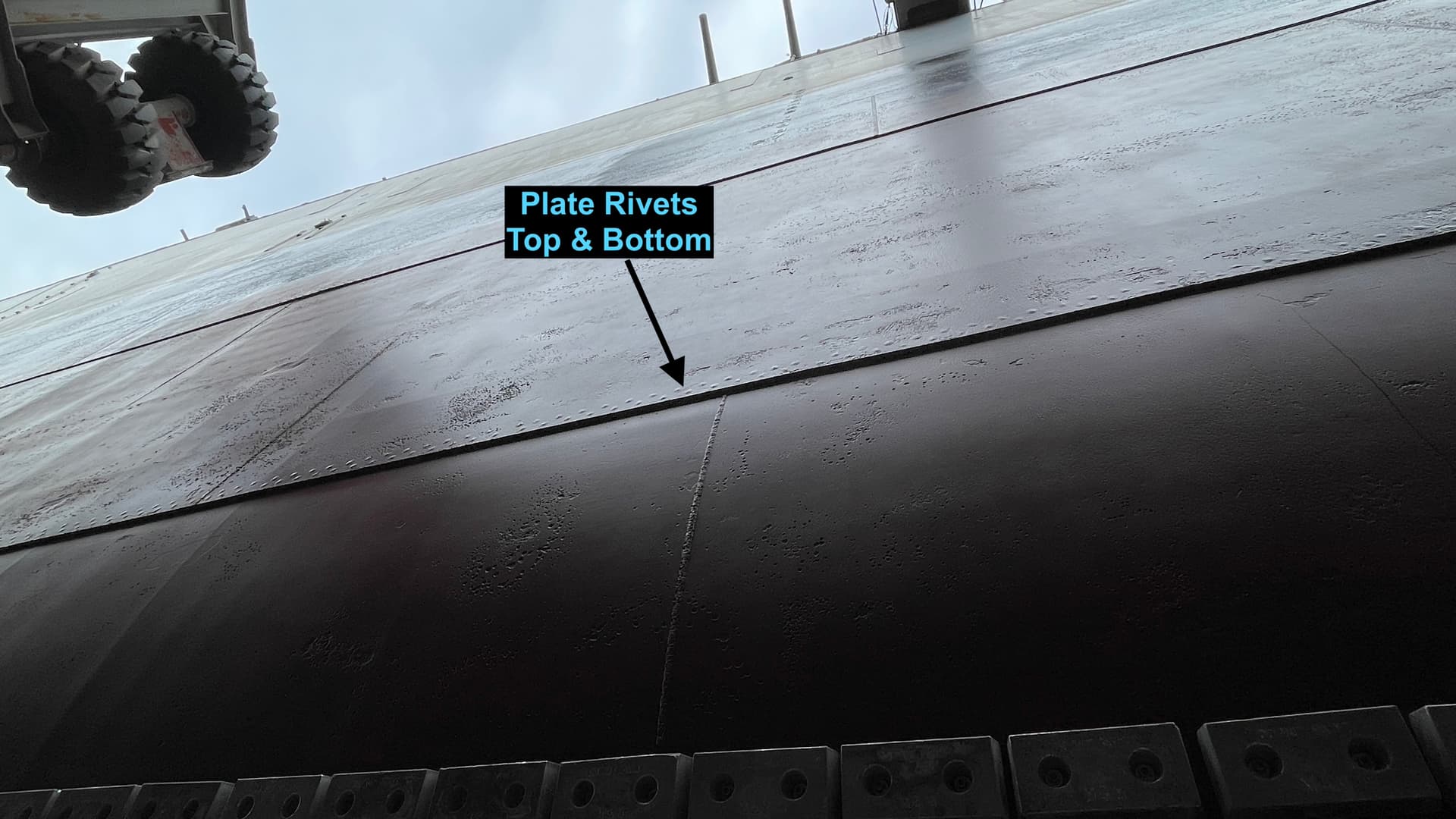
As you can discern, it’s not overly complicated. it will require that some portion of that bulkhead to be included the model. The other suggestion that my older grandson made was to detail the far wall to show the ship’s framing and the armor plate installation. Ryan thought that would be a good idea. These is actually very little equipment of interest on the port side of the engine room with the upper deck having electrical switchgear cabinetry and the lower deck being completely bare.

This is the kind of stuff that makes this model both enjoyable and a bit scary. Working with no net!

8 Likes

Starting designing the HP Turbine in ea Starting designing the HP Turbine in earnest and concurrently, its foundation. Speaking of foundations, I got another 9 drawings from John Miano including details of the bracing system around the Main Reduction Gear and Auxiliary Turbo-generators, and the lube piping for the latter. Here’s a couple of WIP shots.

For those technically interested: the HP turbine has 7, cam-operated throttle valves that come on squentially as the forward throttle wheel is turned. But they don’t all enter the turbine at the same place. The first few feed into the 2-wheel impulse turbine at the start of the spool, with the remainder feeding into wheels further along the spool. This enables 600 pound steam to be evenly applied through more of the machine. I will be detailing some of this mechanism. It will be small, but it will be there. There’s still more work to do on this drawing.

Screenshot 2024-12-19 at 10.11.49 PM.png

This is the beginning of the HP Turbine foundation. I hope John can get me some more drawings about this assembly, otherwise, I’m going to be taking some “modeler’s license”. The non-detailed square log on the right is the wall bracket that I will be detailing further. I bought the large format styrene sheeting for the base decking and bulkheads. The bulkheads will not be full since it will block to many sight lines. Instead, I’ll just show bits that are critical to show things like where steam enters the room and the bearings for the prop shafts that pass through the space.

Screenshot 2024-12-19 at 10.18.04 PM.png

6 Likes

I hope all of you have had a happy and healthy Christmas (Hanukkah) holiday, and hope for an equally happy and healthy New Year.

Besides spending Christmas night (First night of Hanukkah) with our daughter and family, I did a lot of design work over the last week. I am declaring the HP Turbine Designed and ready for printing. I now have the actual engineering drawing of the welded foundation that supports this vital piece of propulsion and feel confident that at least the main propulsion portion of the project will be as accurate as I can make it. Even with hundreds of pictures and lots of actual drawings, there are still unknowns that i have to guesstimate.

The drawing of the frame on my last post was from my imagination and I will now draw it exactly as it was originally designed.

Meanwhile, the HP Turbine rotor, with my previous experience with the LP Turbine, was pretty straight forward. i can’t say the same for the complete throttle valve structure. This bit took days to get into an acceptable form… and I don’t know if it’s printable in this form. It depends on where the supports are going to fall. The HP throttle consists seven similar mechanisms. I drew them the same even though there may be some variatons between them, but no one will know. They’re very hard to visualize in their 1:1 form due to the forrest of piping and insulation that surrounds them.

Let’s get started looking at a nice finished rendering of the completed unit. Like the HP, it will be printed in multiple parts. I would like to print the throttle body integral with the upper housing if I can. But I could print it separately.

HP Turbine WIP.pngHP Turbine WIP 3.pngHP Turbine WIP 2.png

This drawing project, although it may not appear as such, was one of most challenging I ever drew and forced me to get better using a plug-in call “Curviloft”. I keep forgetting I have this app because I don’t have many times I need it, but when I need it, I REALLY NEED IT. I permits SketchUp to create organic, compound curved shapes. There were two instances where I needed this on the HP Turbine. The first was the funnel-shaped discharge outlet that conveyed 46psi steam to the LP Turbine. I first made it a regular cone, but it looked terrible. I used the Curviloft function where you draw a series of contoured frames and the app skins it over like building an RC airplane out of balsa old-school.

Screenshot 2024-12-23 at 5.23.38 PM.png

The next opportunity presented itself in properly shaping the 600 psi steam inlets on either side of the throttlle housing. There are no square edges on most of this equipment since they all massive casting and they are usually associated with lots of filets. In this case the shape had to curve in one plane and then in two when it had a full-surround filet where it joined the main body. Again, I tried to do it with simole SU shaping, but woke up thinking about how to form the frames and use Curviloft.

This shows the early attempt with its square entry.

Screenshot 2024-12-25 at 12.07.47 PM.png

Here was the shaped object drawn off the main housing.

Screenshot 2024-12-25 at 12.01.17 PM.png

And lastly, after attaching and forming the rest of the area around the protrusion. It took a lot of work removing the old shapes and preparing the area for the new work. This is often a problem with what I’m doing. I first draw the parts as best I can directly from the drawings. Then I start heavy editing and modifications based on pictures and then, worst of all, getting it all in a position to be printable. My drawing time would be hours shorter if i didn’t have to be concerned with solids, reversed faces and thickness to make things printable.

Screenshot 2024-12-25 at 12.07.13 PM.png

The last utterly enigmatic design work was coming up with something resembling the 7-valve cluster that makes the ship go slow or fast. I have another plug-in that quciky lets you draw springs (or any kind of spiral/helix) which I put to good use creating the valve springs. I was going to do a cutaway of part of the valve body, but the innerds are not right and making them so is more time than I want to spend. Furthermore, the details would be so small in 1:48 as to be meaningless. As it is, some of the details may be too small to render successfully… think about those turbine blades in scale thickness. I am not duplicating the cam mechanism that controls the sequential valve opening. I don’t have any accurated information about it and it’s buried amid the valves so it can’t be seen.

HP Turbine WIP 4.png

​Like this….

At each point in the drawing process I would export the parts as an STL file and load it into my ChiTuBox printer slicer to see if it is a full solid object and printable. I don’t spend time adding supports, but it’s a good way to catch anything missing.

HP Turbine Upper.png

Screenshot 2024-12-25 at 12.27.19 PM.png

This is a complicated part as it is, so including the valves on top might be overkill for the printer. My other choice is to print the entire valve body separately and attach later. With the HP unit designed I can turn my attention to building its foundation based on the scale drawings I now possess. Stay tuned!

7 Likes

After returning from a New Years Eve wedding in Miami, I got a gift from Southwest Airlines; a nice, annoying head cold. This kept me out of the shop, but not off the laptop and a lot of design work contrinued. The HP turbine is done and with accurate drawings of its foundation, I was able to draw that too. I stopped work on that because it was now esssential to finalize the main reduction gear since the MRG’s fore foundation also supports the aft end of the HP turbine foundation. I continued designing the steam piping, but see a decision lurking. Too much piping will obscure the wonderful machinery that lies below. I’m also thinking that the undersides of the main piping will serve as convenient locations for LED lighting.

I was able to estimate the actual MRG gear diameters using the overall ratios, the output speed, and the relative space within the housing. I produced a spreadsheet to do the calculation. There is a slight difference in diameters between the first pinion on the HP and LP sides. The HP input rpm is 4,905 and the LP is 3,913, but the second pinions on the bull gear have to be spinning at the same speed to create the 202 rpm at the properller shaft. After doing all this, I realized that viewer will not discern any difference so I made both sides the same. I’m cutting away the gear covers on both sides so the innerds can be viewed from either direction. i did a test setup in the print slicer to print the gear set (sans bull gear) as a single part facing vertically so no supports will go on ANY gear teeth. It will work.

Screenshot 2025-01-07 at 10.31.25 AM.png

This was a very challenging piece to draw. I was fighting all the usual SketchUp challenges coupled with the mechanics of creating parts that will assemble correctly.

The frames were equal on both sides. I drew the overall shape and then slice in half using a big rectangular brick as the cutter and insecting the faces and removing the half I didn’t want. You group the good half, MOVE-COPY it directly next to it, and mirror is using the MIRROR tool. Match them up a mating corner, explode both parts and then remove the center line making them a single part with perfectly symetrical features on both sides.

Screenshot 2025-01-08 at 6.25.25 PM.png

Another annoying, but necessary detail with making a SU drawing 3D printable is all the faces being “normal” not reversed. I set my default colors so reveresd faces are quite obvious. When reboring some of the bearings, the inside faces come out reversed. If this was just for an illustration, it wouldn’t matter a whit, but to print they must be all forward faceing. I had to go back and reverse then on facet at a time. It’s very finicky, time-consuming work that must be done. Reveresed faces are seen as missing in the slicer and missing faces don’t print. This screen shot was taken in the middle of the face reversing task.

Screenshot 2025-01-06 at 12.52.36 PM.png

I “line bored” the bearing mounts by creating a set of shafts that were used to “cut” their channels in all the support struture. Even with this cleverness, I still created problems for myself when I didn’t have the frames properly aligned when I did the cutting. I have to close up all the bearing holes and redo the whole operation. I used the same setup to cut corresponding bearing in the gear covers.

Screenshot 2025-01-05 at 4.09.46 PM.png

Speaking of gear covers. While seemingly uncomplicated, they took a lot of hours to get resonsable. I was shaping them without paying enough attention to my pictures. Like the gears, I don’t have technical drawings of these highly-visible parts. When you come down the ladder into the engine room, the first thing you see is the top of the MRG. I tried to fix my errors, but gave up and redrew the part from scratch. Since the same on both sides—although one side has the electrical turning gear attached—Made one, copied it and then mirrored it using a -1.00 scale factor.

When I first drew the gear covers I had the lid face curved on all sides. After closer look at the pictures, it was only curved on the front and back edges, not the sides. Making the curved edges is EASY. I have an SU Plugin, Fredo6Corner, where you dial in the amount of edge to be curved, select the edges and click. Voila! Curved edges. But… to fix curved edges, or in this case, remove some of them and re-square the edges, it’s a complete pain-in-the-derriere. It’s not hard to erase the curve, but it’s very finicky, re-laying the lines to create the square edge. You make heavy using of SU’s “inference” facility that highlights the line end that corresponds to an adjacent/nearby edge. You draw out one segment at a time to the inference point of the bottom line, and then connect these lines to make faces, and finally close the long wall. It’s complicated to write about it and complicated to pull it off. This shows the lines pulled out to the correct distances waiting to be connected to the same form on the other end of the part.

Screenshot 2025-01-10 at 3.38.32 PM.png

Today I spent time building the output end of the MRG. I didn’t have a drawing of this, but a good photo I took. So the upper works are complete. I still have work to do on the MRG lower foundation and lubeoil tank upon which it all sits. The cutaway area is what’s going to be printed.

NJ ERP MRG 3rd Render.pngNJ ERP MRG 4th Render.png

The X-ray view shows the bull gear and why the housing so darn big. The bull gear is about 13’ in diameter. The real one could be bigger or smaller. I don’t have any information about it, but this size fits the housing appropriately, and I do have housing drawings.

Screenshot 2025-01-11 at 1.55.55 PM.png

So here’s some eye candy to brighten up a cold winter day (for us Northern Hemisphere folks). It’s definitely starting to shape up. Notice that there’s now machinery on the top of the main condensate pump. The big four (HP/LP turbines, MRG and Condenser) are now almost finished. I don’t expect that any of the auxiliary equipment should be more difficult.

This is the high pressure side:

Master Draw WIP-1.png

And the low pressure side:

Master Draw WIP-2.png

5 Likes

I’m almost finished designing all the parts of the primary propulsion system. In addition to the drawings, these parts have been prepared for printing. I just placed an order for a larger ultrasonic cleaner to replace my smaller (and no longer working) unit. Bigger parts require bigger cleaning systems. I also ordered another UV curing light to double the illumination in my post-cure box. With the larger box, and with the inverse square rule regarding electromagnetic radiation, the curing power was diminished. The second lamp will solve that problem too.

To the best of my ability I created the aft-end main reduction gear foundation that abuts the bulkhead to the #4 fire room. It’s a very hard location to photograph and the drawing of this area in cross-section is equally ambiguous. I never let confusion stop me. I just added my own bit of naval architecture and pressed on.

This shows the aft-end of the MRG and the #3 propeller shaft penetrating that bulkhead. You can see the structural steel retaining the unit, but it’s a very oblique view so getting good dimensions was dificult. Furthermore, the space is only about 3’ wide and hard, if not impossible, for an 80 year old guy to get any closer. You can see piping and valves buried in there. In 1:48 and considering the lack of visibility, I’m not modeling them! You wonder how a human can reach that valve in 1:1 scale. I found a lot of valves in places like that. It has to be reached from the bilge which lies below all this.

IMG_6375.jpg

And here’s the drawing showing that area from the same side. I challenge you to make sense out of it.

Ele Cross-sec MRG aft.jpeg

That said, I did get something that can be created in 3 dimensions. And it looks like this.

Screenshot 2025-01-15 at 2.09.46 PM.png

I also finalized the HP turnine foundation. I was wondering why the #3 fireroom bulkhead was on an angle. I then realize that it wasn’t! The entire propulsion system is on an angle to correspond to the slight angularity of the how the propeller is attached to the ship. All four props and their shafts are angled outboard by, what seems to be, about 3 degrees for the inboard and more for the outboard shafts. Notice too on this overhead of the bilge level the amount of abaft space is taken up by voids and armor for torpedo protection. The ship has a 108’ beam, but usable space inside is only 80’ at the widest. It was a warship after all, not a cruise liner.

Screenshot 2025-01-15 at 12.44.52 PM.png

I had to come up with a better way to attach the HP turbine itself to the its foundation. The plans show the turbine hovering above the frame rails, but I couldn’t determine what’s actually holding it there. I extended upwards the inner stiffeners and matched their curved surface to the HP’s bottom contours. This will facilitate getting all this stuff together and in line.

Screenshot 2025-01-15 at 12.19.36 PM.png

I’m planning on printing the entire HP foundation as a single part, again to facilitate alignment and assembly. The new printer should have no trouble executing this. This part would be too big for my now-obsolete Mars 3 printer. Elegoo just announced a new iteration of the Saturn 4 Ultra with a 16K LCD screen, and some other refinement such as an integral vat heater to stabilize resin temperature, plus a light to accompany the included camers. I’m happy with the one I have, and will upgrade again in a couple of years, if I still doing this stuff.

Screenshot 2025-01-15 at 11.45.28 AM.png

The thing done in this session was to refine and design the #1 & 2 prop shaft bearings. I originally faked this, but then found a good image of the same in the Iowa and, once I have a real thing, I’m no longer at ease faking it. There are a lot of these bearing throughout the length of the shafts. The #1 shaft is 340’ long!

Just to keep y’all from getting too excited, there’s still a massive amount to design, including, but not limited to, 2-1,250 KW auxiliary turbo-generators and their condenser systems, the deaerator, 3-evaporators to generate potable and feedwater from seawater, lots of small pumps and auxiliaries, the main control panel, electrical panels. And then there’s the labyrinth of catwalks, gratings and ladders. Of the latter, I’m quickly coming the realization that too much of this these will hide a huge portion of the equipment itsef. The goal is to show the equipment in ways you can’t see when visiting in person. I have to include some ladders and platforms for scale, but not all.

3 Likes

Looking great Miles. I am envious of your mad CAD skills. I just recently started printing and am nowhere near ready to design my own parts.

IIRC my father told me the shaft bearings were(are ) wood - Lignum Vitae . My dad was a loftsman at Philadelphia Naval Shipyard during WWII and did much lofting for the Big J .

Gino, it’s a very long learning curve. I am literally learning new techniques regularly, and I’ve been using it one and off for 25 years. This project is testing all my skills.

RDT, they are most definitely lignum vitae. It’s quite astounding that the parts that push a 57t, 900 foot long, beast is dependent on the lubricating properties of wood. Did you dad ever talk about what his job entailed?

One of my blog readers on another forum that I post this story, sent me links to two Ryan Syzmanski videos that addresed the prop shafts. I was very happy with my 24" prop shafts. I thought I read somewhere that this was their diameter. Then I looked at the video and found out that they’re 32" in diameter, and solid steel except for the 8" hole down their center. Once I know an “actual” dimension I’m compelled to make the model conform.

That generated about 2 hours of work modifying everything affected by the prop shaft. I also got a good view of the bulkhead Prop Shaft Seals so I changed them also. The 24" shaft scales nicely to a 1/2" in 1:48 so I could use a standard piece of tubing for it. At 32", it scales to something between 5/8" and 11/16". I’m going with 5/8"… 32" is 20% bigger than 24" so I was able to scale up the spring bearings and their supports. I also got a good view of the prop shaft couplings enlarged its thickness and then scaled it up 120%.

I didn’t scale up the MRG’s output bearing becasue they wouldn’t fit in the space. Instead, I intersected the front face with the new diameter shaft and redrew and edited the parts with the new diameter. It also changed the tapered end and that… was a pain in the butt. As I’ve said many times before (and it’s worth repeating), in SketchUp, it’s often easier to draw a part from scratch than to modify it.

The new shafts do look much more massive and, frankly, look bettter to me.

I pause videos that have useful imagery and then do a screen print isolating the parts I want. I did the same with the other video and found some good still images that I didn’t have in my reference library. Every image, even if it’s just a small detail that is exposed, is worth it.

NJ ERP Master Drawing.png

Shame on me for exporting a lot of these affected parts as STLs and then producing sliced print files. I now have to go back and do some of them over again. I was jumping the gun.

Also, my new Ultrasonic Cleaner arrived yesterday and the additional UV curing light for the enlarged post-cure chamber arrived today. That means some of these now-designed components are going to be printed this coming week.

4 Likes

Looks awesome to me.

Check your PMs too.

Hi Myles - Once again , very impressive work on your part. In answer to your question,
yes , my dad often spoke of the work he did on the New Jersey . To all who may be following I hope my lengthy response is not misconstrued as a hijack of Myles’ wonderful thread - hopefully it compliments it .My dad divided his time between the mould loft and the small boat shop . All of his work on the New Jersey was in the loft ( with one small boat shop exception related - details to follow) .
My father , like my grandfather, was a master wooden boat builder and loftsman. Most are familiar with what a boat builder does but perhaps not so familiar what a loftsman does .
Lofting is the process of drawing out full size components of the vessel by plotting points in three dimensions. The name is taken literally from the loft - a large space above the construction areas where the drawing took place on a sterile floor. No shoes please !
My dad was mostly involved with lofting of bucks for the furnace plates . Furnace plates were ( and are today ) those hull plates of compound curvature that required heating in a furnace to form , hence the name . Wooden forms (bucks) where made to form the plates .
Developing these shapes was a highly specialized skill using spherical geometry among others . While my dad did say they had mechanical computers for certain tasks , mostly it was these - his shop books still in their wooden slip cases which I treasure-

  • and that other computer between his ears .

The small boat shop incident alluded to earlier and related to the New Jersey was thus . During sea trials there was one of her ship’s boats ( 50’ Captain’s launch perhaps? ) on deck in a cradle awaiting fitting to davits. Unfortunately it was under the muzzle of a 16” rifle during firing trials . It came back to the boat shop with all the planks sprung away from the stem and all the tankage ruptured.
Thanks again Myles for sharing your wonderful work .
RT

1 Like

I am in awe of people who can do these things. The Iowas (and ships of that generation and earlier) were all “stick built” with frames and plates placed into the building ways and welded right there. There was no “pre-fabrication” as is done today. When I did the Big J bottom tour what impressed me most was the fairness of its lines. The curves and fit of the hull’s skin was perfect! It was a fast ship and that speed was the result of the hull’s shape (like a 47 ton arrow) and the skill of the crafts who shaped and welded/riveted all those pieces together. I struggle to get it right working with a miraculous system of computing and 3D printing. Those guys did it with 3/4" steel plate. Not only were the fore and aft hull joints fitted well, but they were caulked so they wouldn’t create any additional drag. You have to stand right next to it to believe it.

Be my guest to hijack away if you’re going to impart more wisdom.

5 Likes