JLTV UTL M1278 and an RG-33 SOCOM AUV Build Conversion

Well guys, as part of the Convoy Campaign, I’m building a modern truck or two, including the JLTV - UTL, which is basically a pickup truck version of the M1278. A few weeks ago I purchased one of these kits from Sabre Models, so it will serve as the basis for this project. I don’t want to clog up the Campaign thread with too much of the construction so here we are.

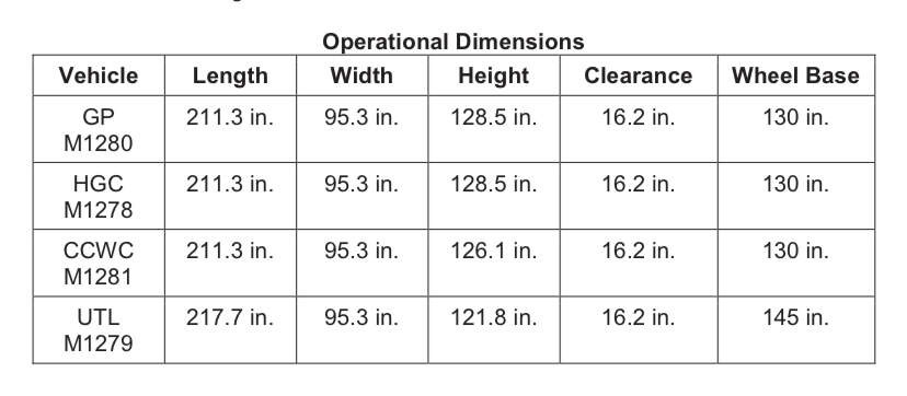
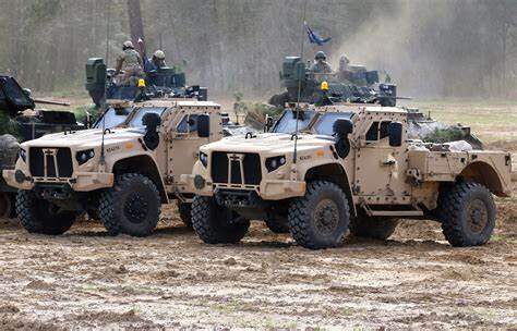
If you’re not familiar with the JLTV, it’s broadly defined as the HMMWV replacement vehicle. The UTL version looks like, and is described as:

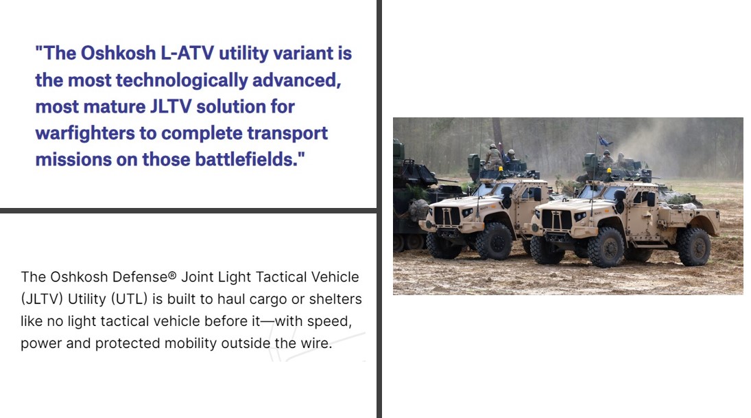
Being a truck enthusiast, this caught my eye as a fun project.

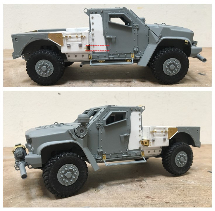
Before jumping right into this, I prepared this visual study:

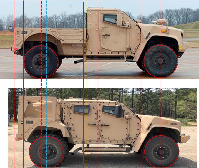
While admittedly low tech, this illustrates a few key points for this conversion. First, refer to the dashed red, and blue lines - the UTL version certainly appears to be a bit longer than the standard version. Unhappily, I can’t confirm that this is the case or not - is it just an optical illusion? well, I don’t know, but am living with the conclusion that the UTL is a bit longer.

Next, for general orientation the dashed yellow line represents the rear of the UTL cab, and you can see where it hits, about halfway through the standard model’s rear door. To the left, you can see a thin red line - it turns out that the running board length of the two trucks is the same, which is very helpful, as the kit includes some well defined mounting points in this location.

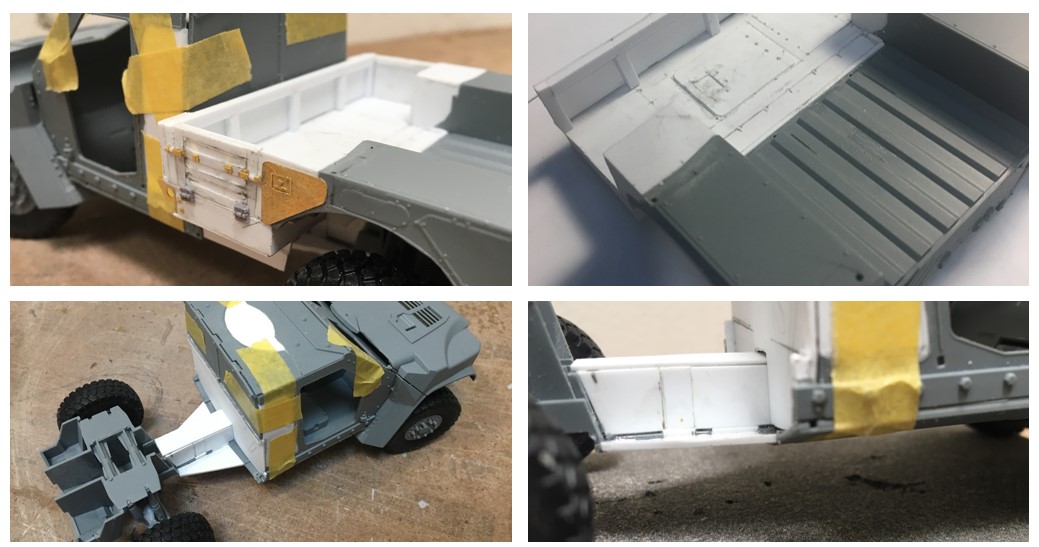
So, with this suspect information in hand, I went about cutting:

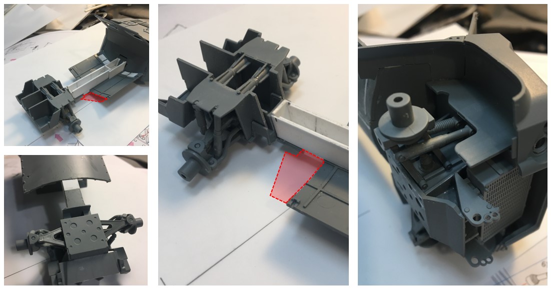
I realized I didn’t include a before picture - perfect! So, the chassis on this model is actually the hull of the truck, which is characteristically similar to what you see under an MATV, rather than a typical two rail, or unibody chassis.

For the build, the hull was cut right next to the running board mounts - you can see in the red shaded area where the hull was. I did not cut this straight across, and instead kept a short segment of the rear of the hull in place, as you can see in the lower left picture.

Then, measured the approximate distance I needed to add to get closer to the right vehicle length, and added a longer sheet of styrene to the short segment to the rest of the hull, adding a small filler piece (the short sheet of evergreen in the pic) to get the chassis to the desired length - whoa - sorry about that rambling description!! bottom line, the hull is longer now :smile: and, as hoped, is rigid! :smile:

Next, added what looks like a trans tunnel - but it’s not - because I cut the back off, there was no longer a way to support the floor of the crew cabin, so the tunnel is a base for the floor to rest on, and adds more stability to the whole thing.

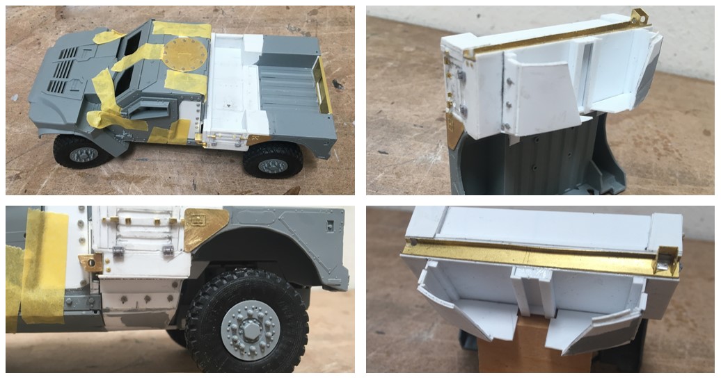
This process went relatively smoothly - I made some measuring mistakes, but was able to get things where I want them to be :sweat:

The Sabre kit is pretty nice, it goes together pretty well. For those of you familiar with building MATVs or other vehicles with the TAK4 suspension, you are familiar with some of the challenges - a third hand would be useful! All of the parts work as they’re supposed to, but assembly requires some patience.

And this is how it worked out:

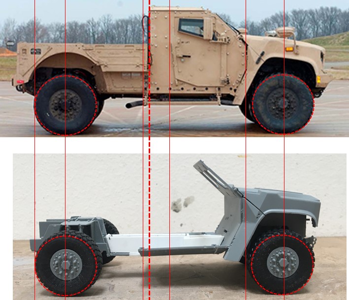
Again - an optical illusion? I really don’t know, but I’m sticking with it! The kit includes posable steering which is really pretty easy to build - much easier than converting a kit not intended to steer!

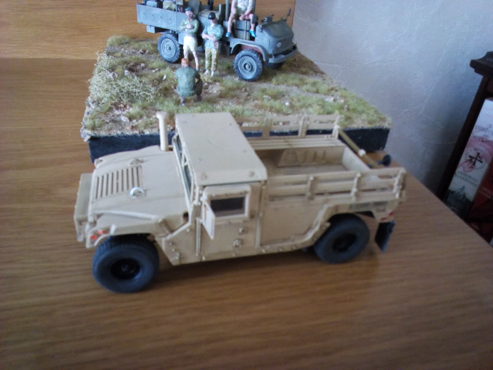
As a scale reference, I compared an HMMWV, this, and an MATV:

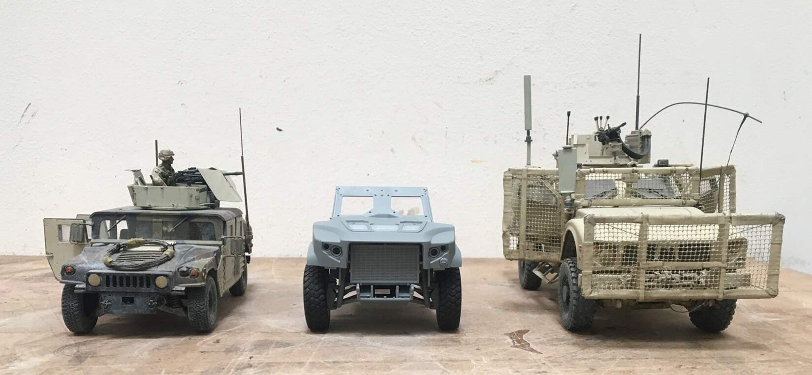
I think it looks pretty cool. I’m also an off road racing and driving enthusiast - I like the styling, and that the rig includes dual front and rear shocks, what appears to be a fair amount of suspension travel, and good chassis clearance.

OK, on we go, thanks for having a look,

Cheers
Nick

13 Likes

Rats Nick you bet me to it, i did the same same with a HumVee a little while ago

4 Likes

Nick,

Might be too late as you’re probably already done :crazy_face::upside_down_face: but the height and length are different according to this https://imlive.s3.amazonaws.com/Federal%20Government/ID262475967522175197973698392766791648919/03%20Appendix%201_%20JLTVA1%20Maintainer%20Training%20POI.pdf

HTH

4 Likes

About the optical illusion or not.
You have the answer in those comparison images with all the lines.
Same running board. The exhaust pipe ends the same distance
behind the running boards
BUT
there is a significant difference in the opening between
the end of the exhaust pipe and the rear wheel.
Since the wheel and the exhaust pipe end are both in almost the same vertical plane (place a vertical board against the side of the vehicle) there is no optical distortion changing the relation between those two items. Objects closer than or further behind that optical plane will move in relation to each other and the wheel-exhaust pair.
Tank_1812 has already provided the correct answer in his post above mine (15 inch frame stretch)

4 Likes

Hi Nick
Totaly off topic but could you says me where you found the mesh that you used on your M_Atav? I don’t find square mesh with 2x2mm even in wedding webshops for my M-Atav and VBCI…
Thanks in advance
Stephane

Well, it seems my assumption that the truck needs to be stretched was right, thanks @Tank_1812 Ryan and @Uncle-Heavy Robin! Robin, yes, I locked in on the running board, which became a key measurement point for the cab cut-off. I didn’t pay enough attention to that tail pipe!

As it turns out, my guess was off, by about 1/8", which while close makes me wonder - should I try and pick up the difference? How much damage will I do trying to fix this? :thinking: as is, I am pleased that the solution is fairly square and strong. If I cut and try and splice in the short segment, will the chassis remain fairly strong??

I have to work today, so won’t have the time for a while to get after this, but I will have time to ponder :thinking: to cut or not to cut?? :smile:

@StephaneHERVE , hi Stephane, I can’t quite remember what material I used. As I recall the material you see came with junk box exchange I did with a friend here at Armorama years ago! I do remember the material was/is very strong, and not easy to work with. It was/is hard to cut and get oriented and fastened correctly in the frame. I’ll look through my various junk boxes and see if I can find any remnant. I might have been so frustrated using the material that I threw out any I might have had left!

OK gents, have a good week, and Ryan and Robin, thanks again -

Cheers
Nick

2 Likes

Many thanks for your reply Nick!

Well, @Tank_1812 , Ryan, with your exciting news:smile: and a moderately productive work day, which included getting some tax forms I was waiting for…and having a client cancel our call…well, what’s a better alternative? fixing a model! So, out came the knife and saw:


And off came the rear end. At least I didn’t need a torch… :smile: As you can see on the right - the big cut-off, and on the left, a multi-spliced chassis, which is now 3/16" longer than before, resulting in a vehicle that is indeed, 15" scale inches longer, as it should be!

Now, on to the rest of the build -

Cheers
Nick

4 Likes

I wasn’t going to follow you around with a ruler but I understand not being able to keep it as is.

The work looks good. :+1:

2 Likes

Unhappily, you provided me with a mental ruler, which was just too obvious to ignore! :smile: At 1/35 scale that little bit makes a difference!

Cheers
Nick

2 Likes

Hello gents,

Next up see how the bed will work with this -

Short of going step by step - to pull this together, as you can see in the lower images, the hull chassis gets extended rearward, using sheets on both sides of the central chassis. Then, on to the bed. I saved a portion of the bed that came with the kit but it had to be cut up quite a bit to work. The wheel openings were carved into a circular shape, rather than the more angular pattern on the standard version. Then extend and detail the upper side of the bed.

A challenge here is that the wall closing in the cab needs to stay removable for a while still, which means the bed needs to stay removable too. At one point, I was going to add some detail inside the cab, but that is getting less likely. I like to build details if the kit will be used in a dio, so the effort will be obvious enough, and because this vehicle is mounted on something, its less likely I’ll snap the doors off accidentally.

In this case, this will not be on a dio, so the amount of detail in the cab is likely to be minimal. But, as I was pondering this, I went about making a bed that would remain removable during construction:


Hopefully these pictures are legible enough to make sense - the idea is to match the curve of the hull under the cab, in the rear under the bed, and that the two can be glued together to look seamless enough. This was a bit tricky.

As you can see in the photos on the right, I built a chassis spine connection under the bed, which defines the center line. Then, went outward on both sides to match the hull location under the cab - which is curved, sloping, and tapered inward towards the rear - yeah - this went together right the first time :smile: No, it didn’t. I think it was worth the effort, as when it’s glued together, the connection will be pretty snug.

OK, on we go -

Cheers
Nick

11 Likes

These are things I can’t do. Interesting idea.

2 Likes

Following along for this one for sure. I’ve also planned this conversion. You’re doing a great job on this build and especially the error recovery.

With all of the info illustrated so-far. It will be an easier path for me :slightly_smiling_face:

2 Likes

Styrene Genius.

1 Like

Good morning model builders, I managed to do some work on the JLTV.

@Makinen, hi Piotr, well, like anything I suppose, with some practice, who knows? maybe you’d really like doing various conversions. If you decide to give it a go, I wouldn’t start with a really complicated project. I’ve found that paying attention to small things makes a big difference with this type of project. For example, if you don’t cut parts square or in the shape you really want, it will haunt you - in this case, as I didn’t initially set the chassis to the correct length. It turns out that if I had left it, the bed just wouldn’t look right. Similarly, some “un-square” cuts can lead to other things becoming unsquare, and can be a challenge to fix once you figure out your mistake. These unsquare parts can also become increasingly visually apparent in obvious places as the build moves forward.

@KoSprueone, hi KSO, thanks for dropping by, and hope this is helpful for your project. Once I was well into this it occurred to me to get in touch with @18bravo for some images - the info he sent over is really helpful - and again, I should have reached out sooner! There are a few details I built, only to discover I was off…well - there you go.

@SSGToms , ha! Thanks Matt - yes, I enjoy trying, but, I’m not quite at the level you suggest!

OK, on with today’s update:

You can see some headway. For this update, mostly adding kit parts and filling in some gaps.

@KoSprueone, I include the two dashed red lines (above) - there is indeed a piece of channel along the front edge of the bed. I used some leftover etch for this - as it is adequately thin and strong - unhappily, it’s a bit too tall - maybe 1/3 too tall. In some ways, this is fine, as it does allow for making a relatively strong frame beneath the deck. But, by using this, the area below the deck is too narrow.

It turns out, this truck has a whopping 20" of vertical travel at each wheel! wow! and this travel is regulated on-board. As near as I can gather, this is either pneumatic or hydraulic, with the pump/pto and related system, located in the space between the cab and the rear suspension. The way I built this basically passes, but, in reality, there should be more room between the rear rocker panels, and bed deck framing, to (I think ) allow for that system to fit. Again, not a deal breaker, but a bit of a bummer to know now!

This conversion is a bit deceptively simple - looking at the side elevation, it looks like you just cut the back of the cab off, and go - but, it’s not exactly that straight forward. You’ll need to modify the roof, fill the gunner’s opening, and use the upper portion of the kit’s rear wall - keeping a few connection points in tact. I suggest lots of tedious dryfitting and measuring :grinning:, while keeping in mind, that you’ll need to attach a bed and extend the chassis hull - piece of cake! :grinning:

The kit comes with a nice front winch, that goes together easily. It’s only dryfit here, as the kit also includes a fine mesh grill, that will be painted black - and I want to paint it with an airbrush, whereas, I will hand paint the other parts black, over the base sand color.

It turns out there is a distinctive and interesting detail on the the tailgate - unhappily, I made the basic gate before I received the pics from @18bravo, which means my gate is about two scale inches too tall - I made it flush with the sides, and it should be lower…well…anyway, I did make up the rest of the gate with the appropriate details.

Regarding the overall conversion, I suggest you decide early on if you want the cab open or not. I vacillated about this, and might have made things harder than they had to be. If you decide to keep the cab open, I would not start work on the bed until you get the cab modified, painted/detailed (interior), buttoned up, and then start the bed. This will allow for a tighter fit for the bed and chassis hull. If you don’t want the cab open, still work to get the cab closed in then, get after the bed. The way I did it required making the bed as a module, that drops in place, requiring the builder to make some “floating” parts that get locked in when you go to assemble it.

Another subtle detail to be aware of is where you decide to cut the rocker panels. If I did this again, I would make the cut behind the last bolt head above the rear running board, but remember, the rear wall of the cab will be inside/forward of these bolts. I didn’t do this with the rockers, and had to go back and add a short segment of the rockers back - which led to some problems with aligning the PE brackets that visually hold up the running boards.

I have photo of this rig with a CROWS mounted on the roof - just over the windshield, which I will add - the kit comes with a nice 50 cal with a brass barrel - which I want to use!. As for the rest of the CROWS, I’ll raid a PANDA MATV kit I have and scratch the rest.

Ok gents, thanks for having a look.

Cheers,
Nick

8 Likes

It’s coming along nicely. Thanks for the kind words on the photos. All other things being equal, the best references yield the best models. :slight_smile:

3 Likes

Yes - getting the pictures before wielding the knife and saw is a good approach - or, live on the edge and add some excitement to a build - haha.

This is getting some paint:

So far so good - today is good and sunny, so I already went outsider and sprayed on the primer - hoping to get the base coat down later today - have some real work in the meantime.

Cheers
Nick

11 Likes

Looks outstanding.

image

2 Likes

An excellent build Nick, your scratch work is tight and the detailing is exquisite. Look forward to seeing some color on it.

1 Like

Looks good its funny that you are building the pick up version becauces trumpeter/Iluv kit is coming out with it this year

1 Like