Kenworth 963 Super 1/24 scale

Hello gents,

I’m starting a new project, which I’m really looking forward to:
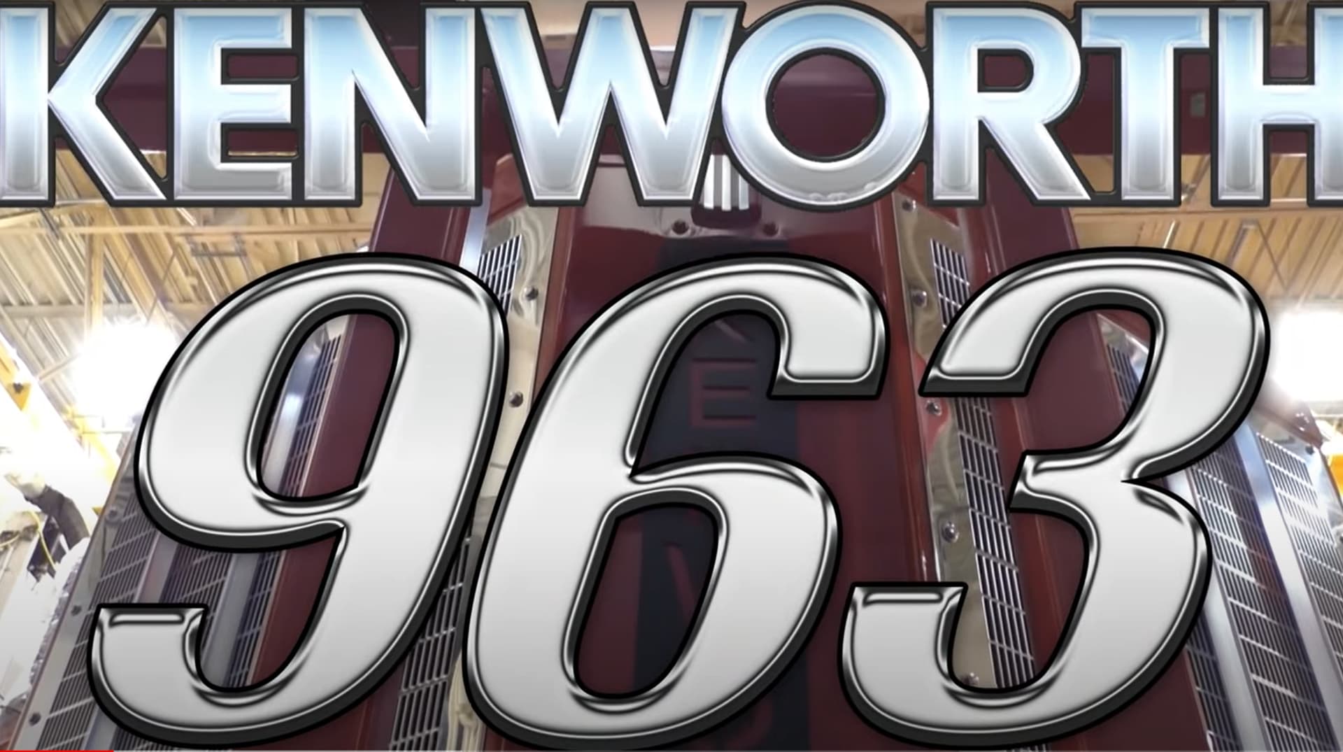
What a beauty!

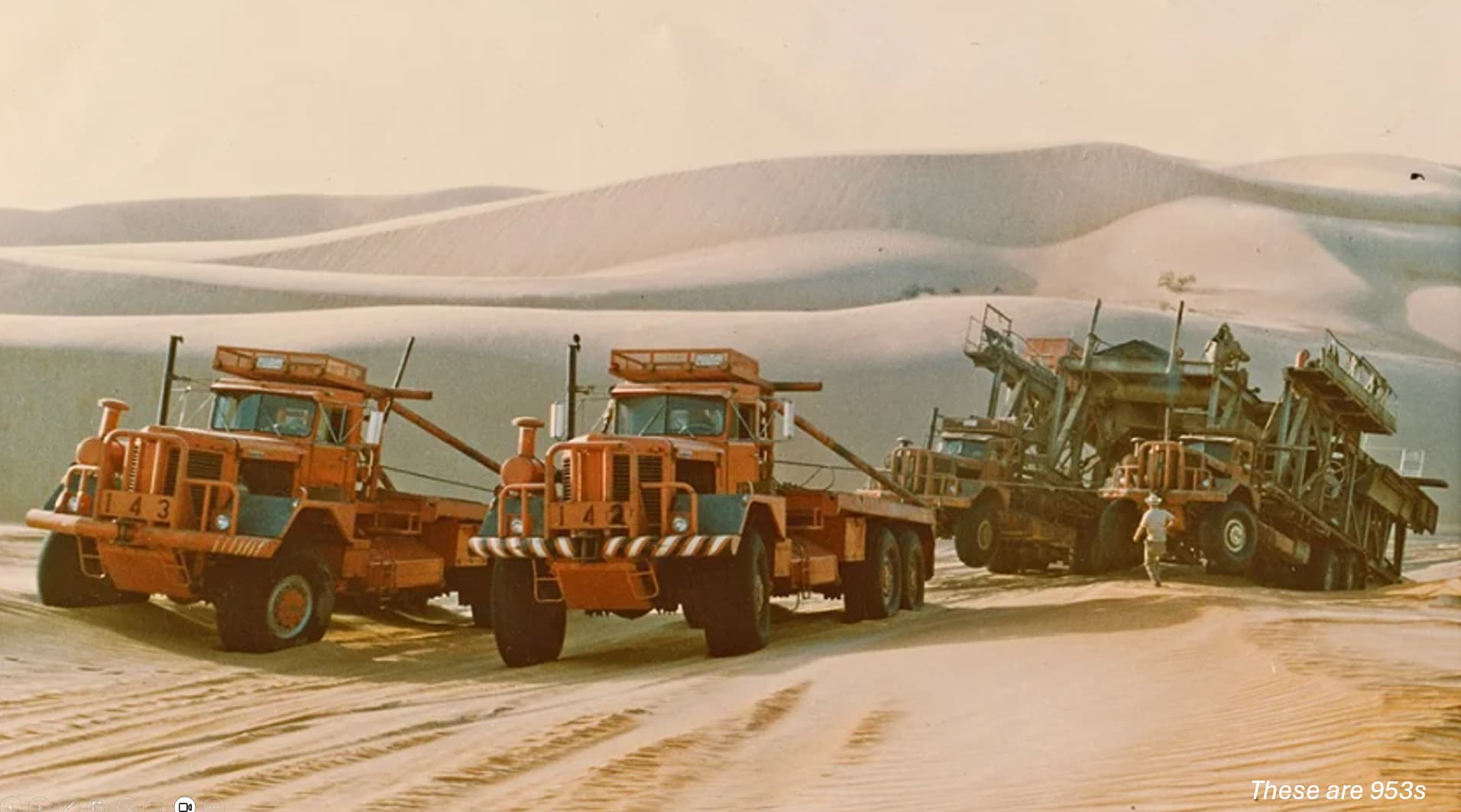
The KW 963 S, is a large, 6x6 used for oil field work - it is a beast! The engine is a Cummins ISX, which turns out about 3,600 HP at 2000 RPMs, and is capable of carrying 100,000 lbs - so, a big truck.

A long time ago, I built on using a resin kit and some scratch work, but in 1/87 scale:

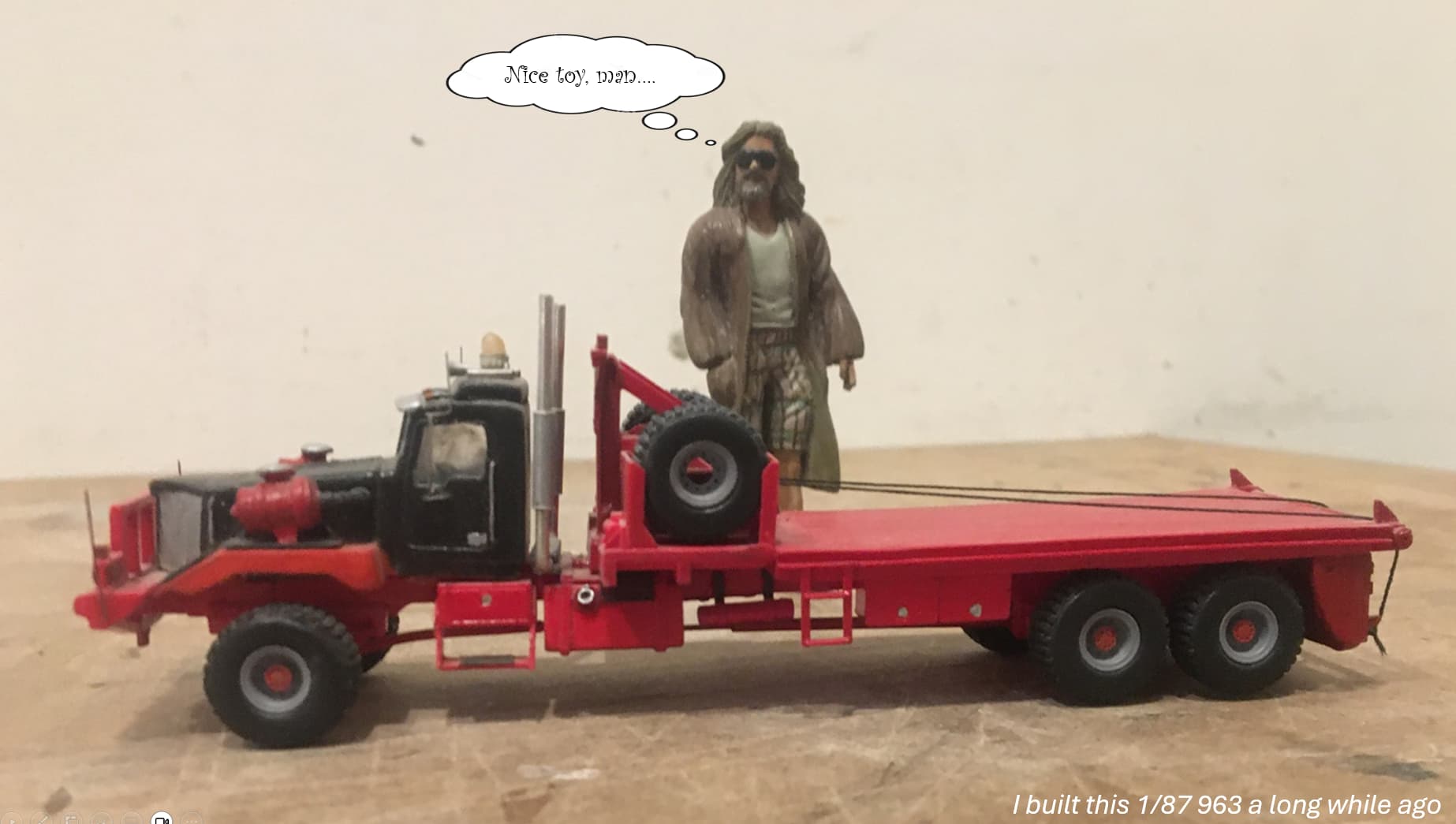
While pretty cool and with nice detail, it’s pretty small - and the tires are not tall enough.

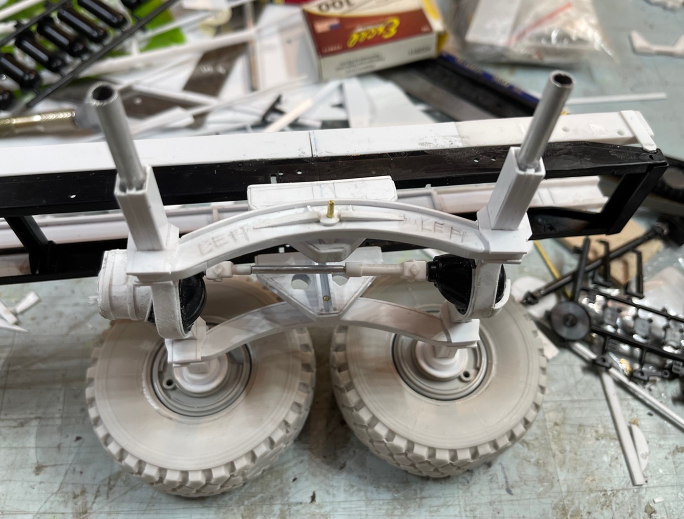
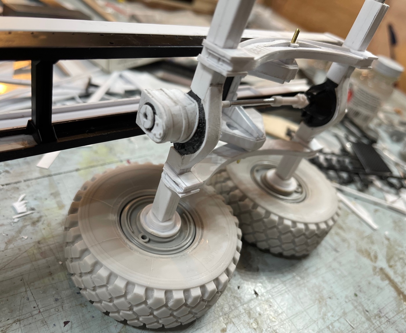
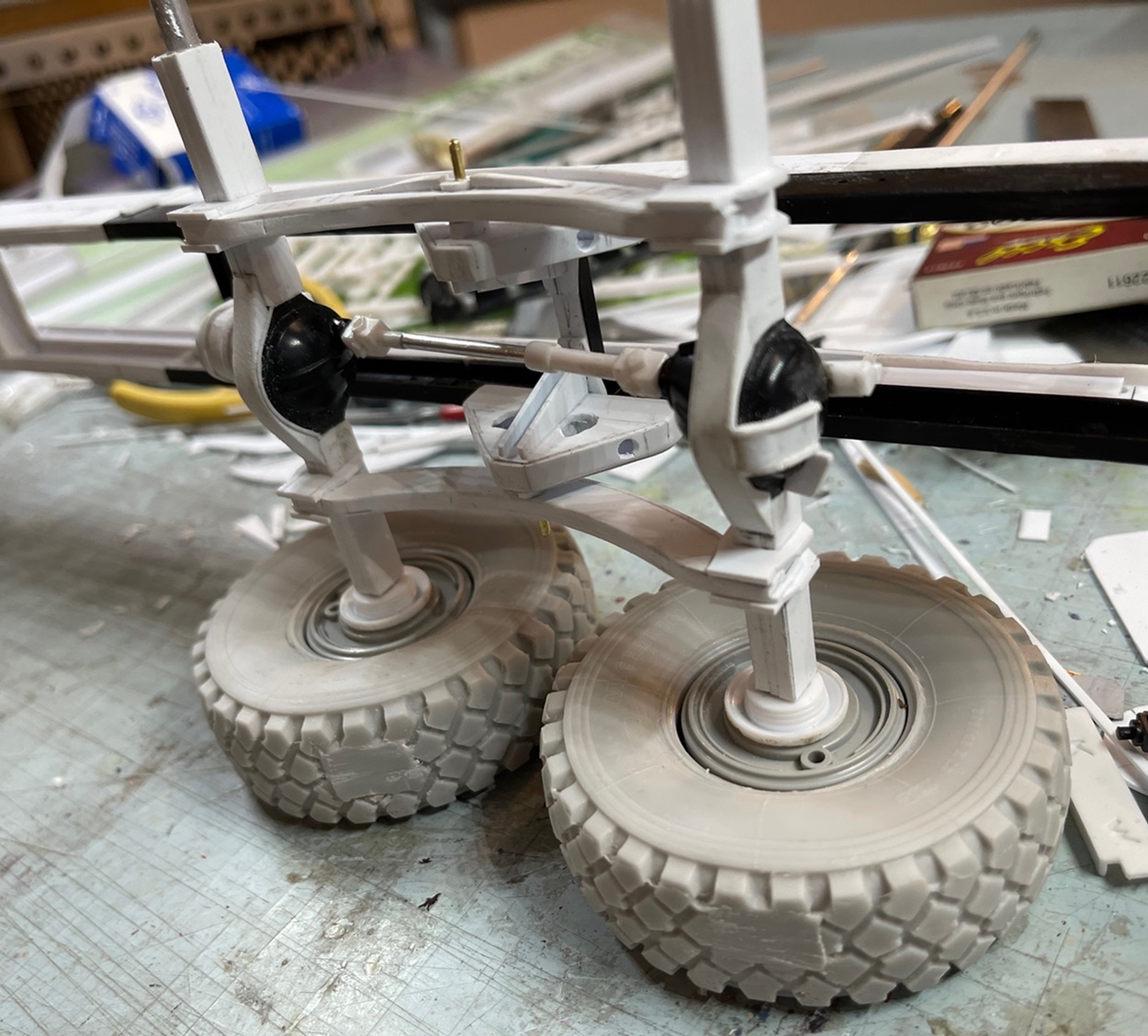
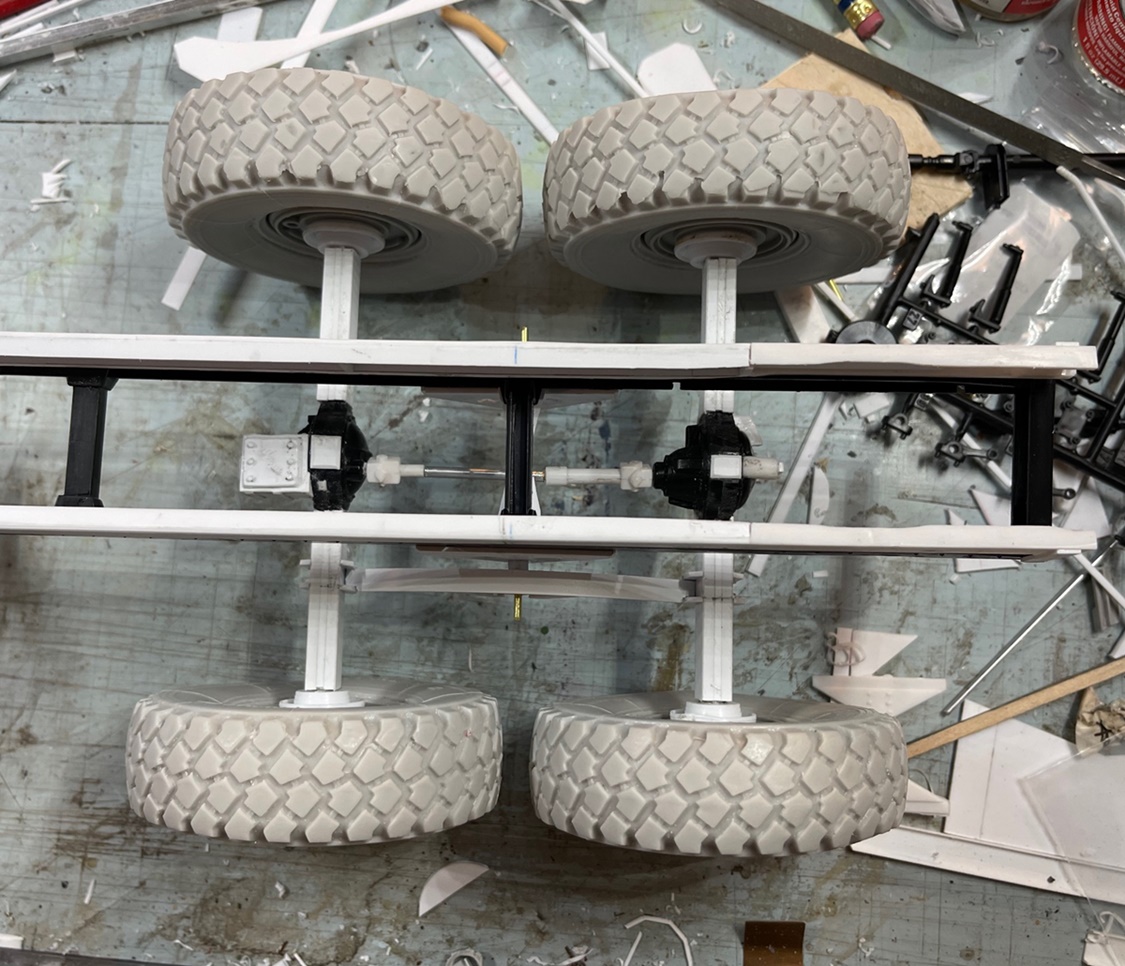
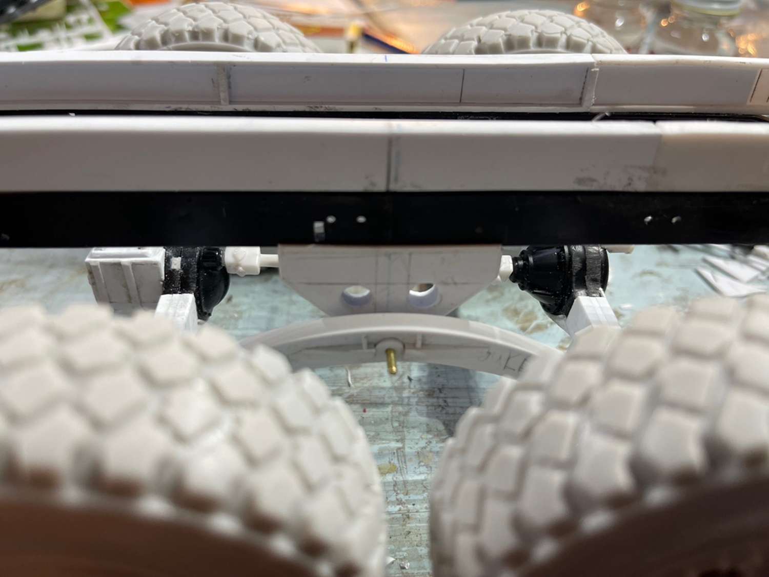
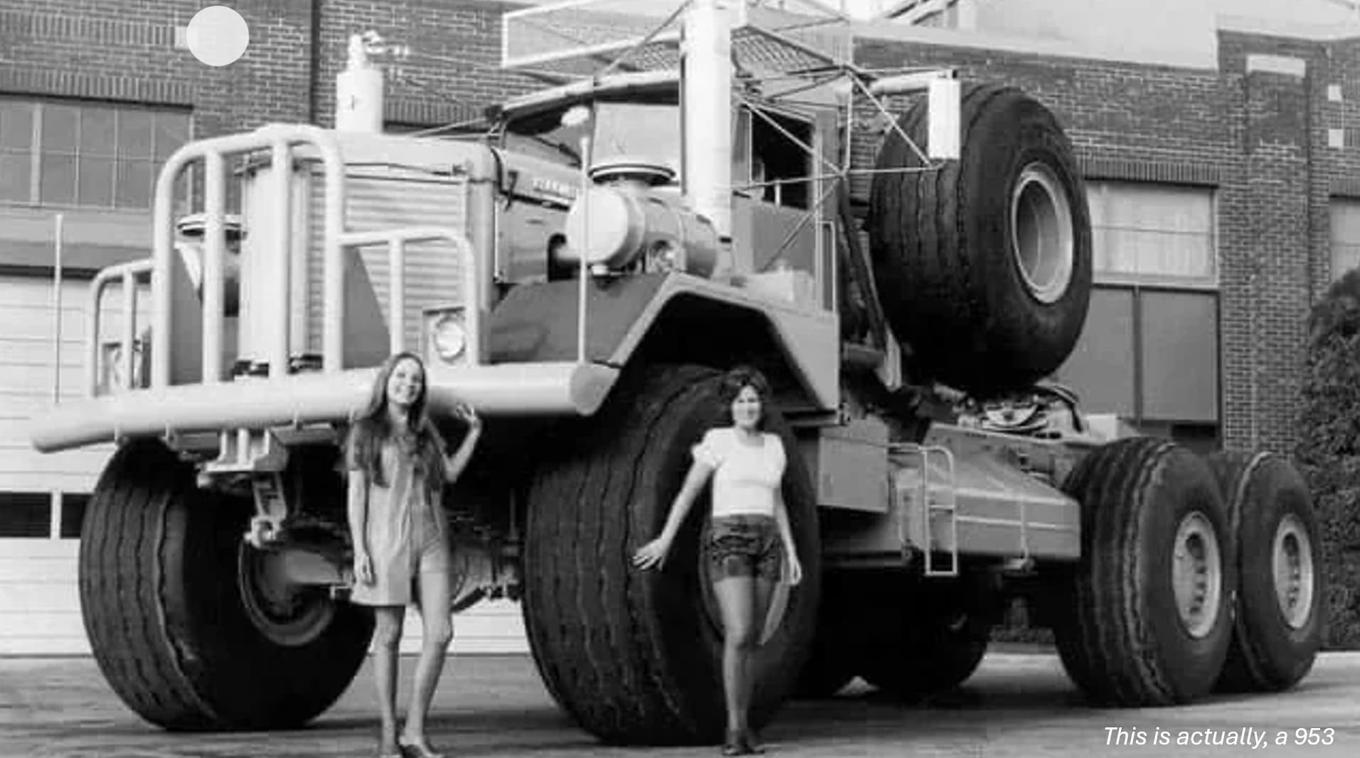
I’ve pondered making one of these for a while, and have not done so because of those tires - they are huge! 73" in diameter. While talking with another model builder about this, I thought to look at the 1/16 scale MATV kit I’ve had sitting for a few years - the tires are an almost exact match:

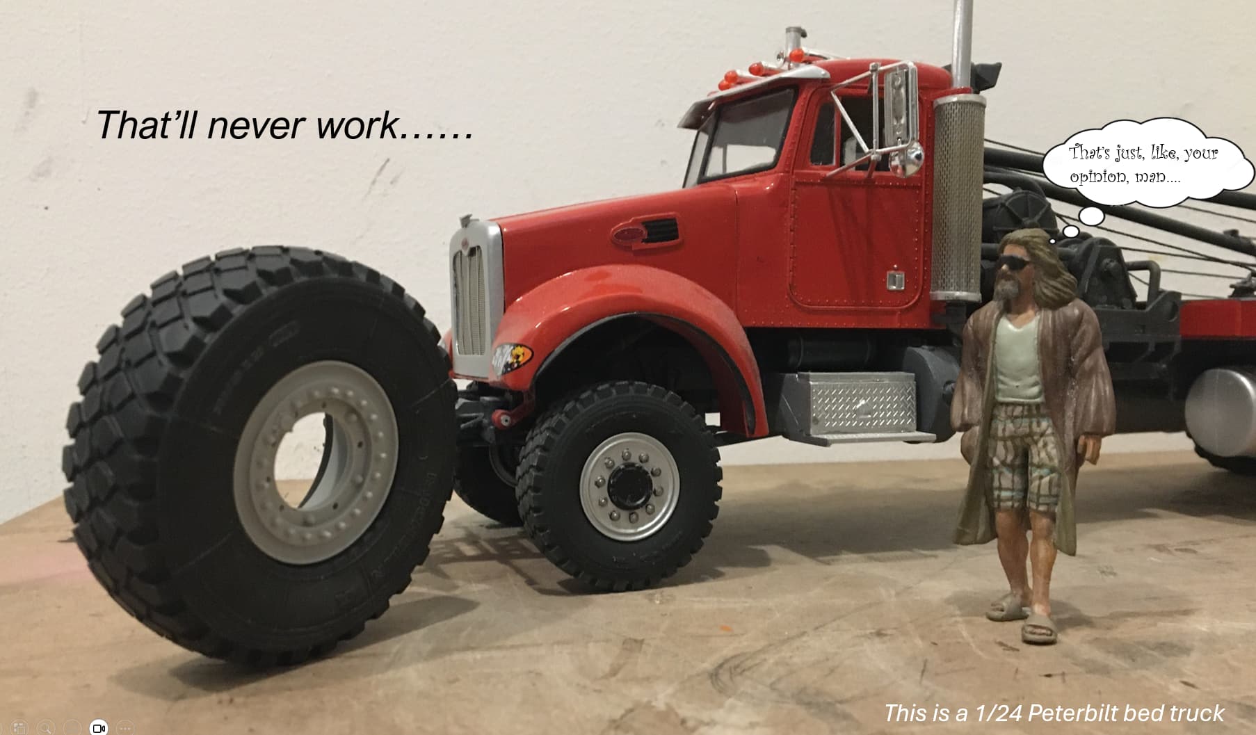
At 1/24 scale, the tires, at 3" in diameter are an almost perfect match, and the width is correct. The wheel size is a bit large in diameter, but I can live with that. I looked on ebay etc for for a few more of the tires, as this is a 6x6 with no luck, so, I opened the wallet and ordered a resin set from Blast Models…all I’ll say is they are not cheap, and on their way to me. Oh, and while the pics of the real truck show a different tread pattern, I happily have other photos that show a similar tread!

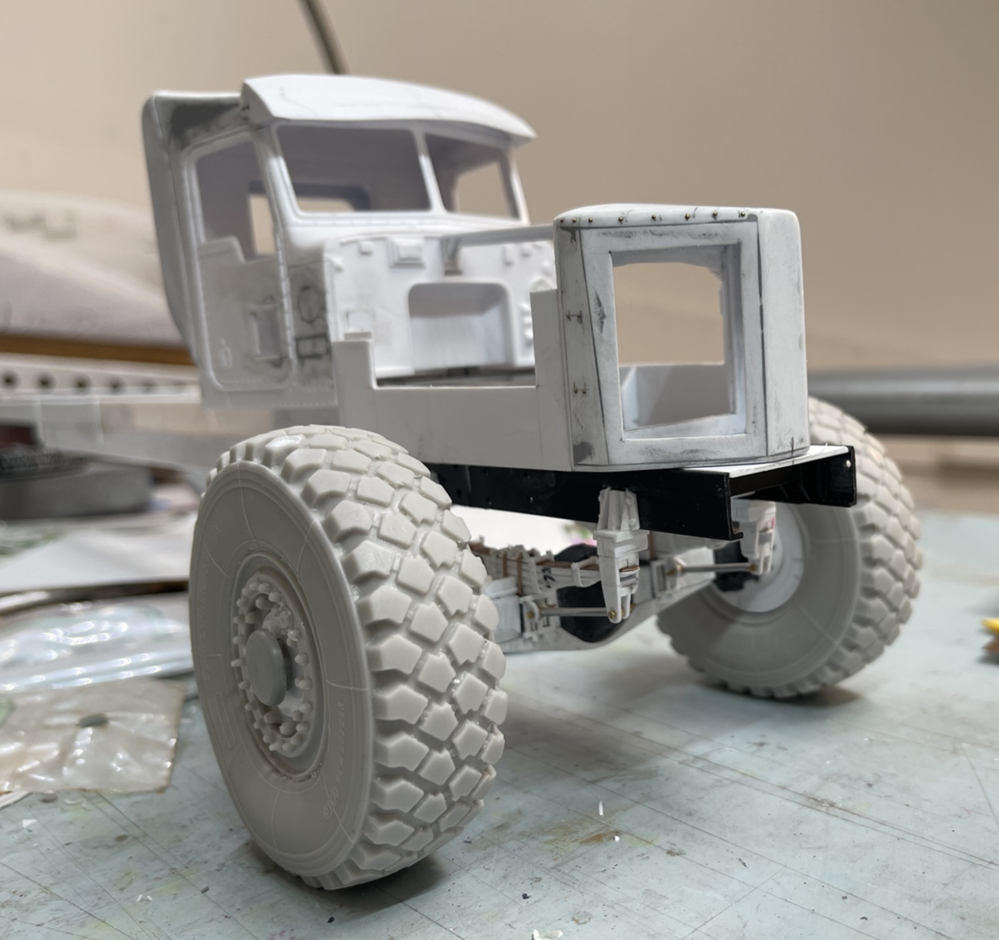
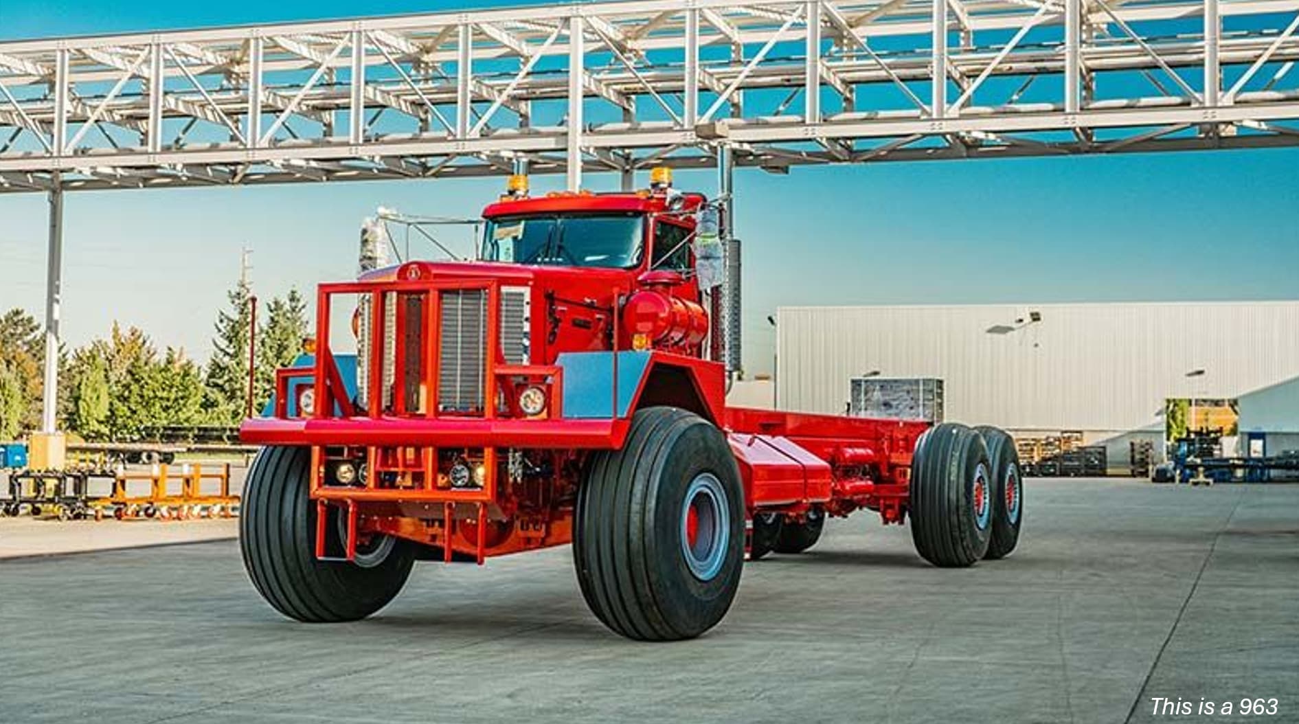
While waiting for the tires, I started work on the cab. This is a bit tricky. Most KW models are in 1/25, and reflect an older style cab. I want something closer to the newer version, specifically the 963, not the 953.

So, I decided to start with, and here, I encourage some of you to take a deep breath, a 1/24 scale…Peterbilt cab - - I know, just try and shake it off. I did this because while some of the the basic geometry is off (the KW has a flatter wind shield), the overall structure serves as a better foundation for change, than the 1/25 KW (which surprisingly, does not have the flatter windshield?)
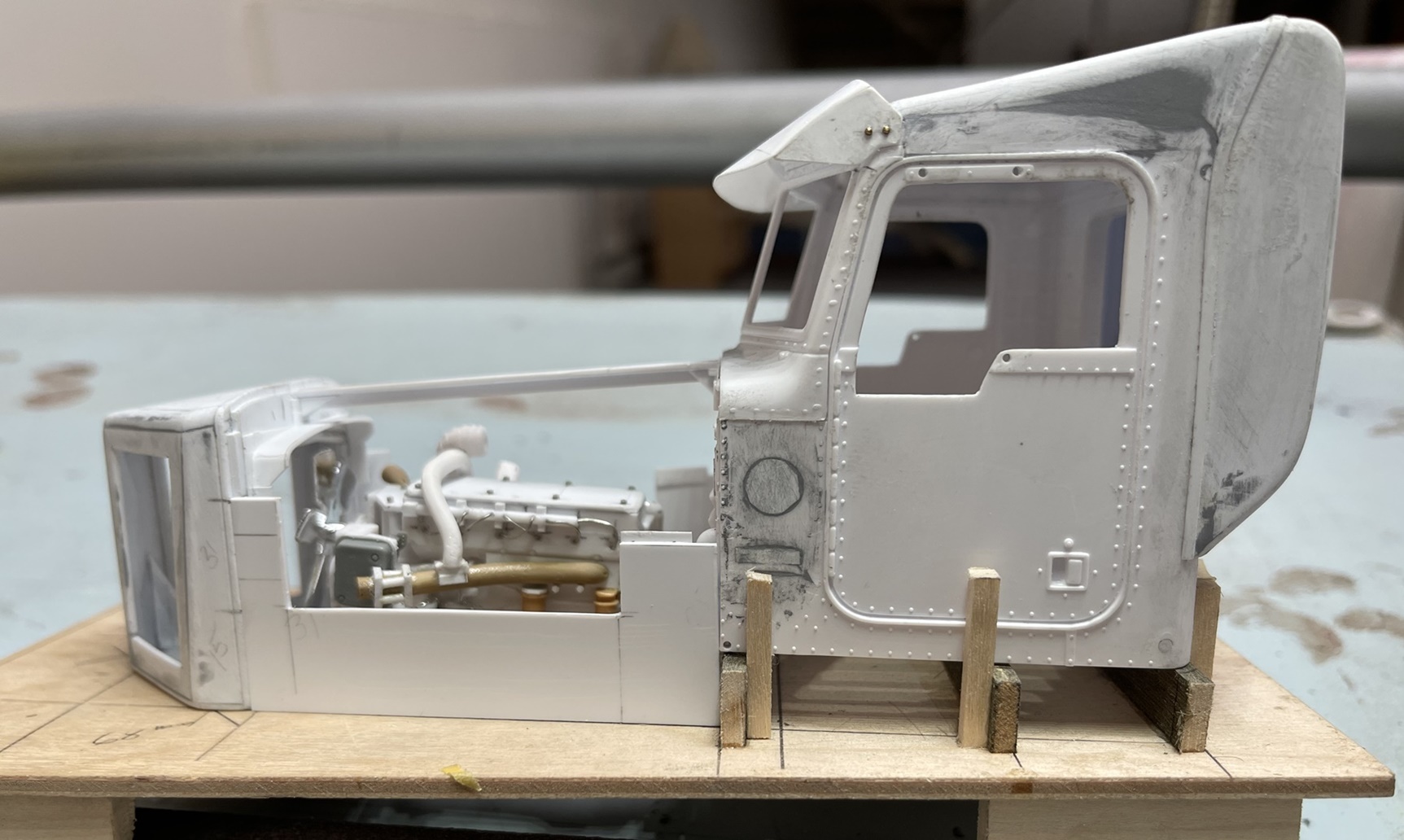
So, here we go:

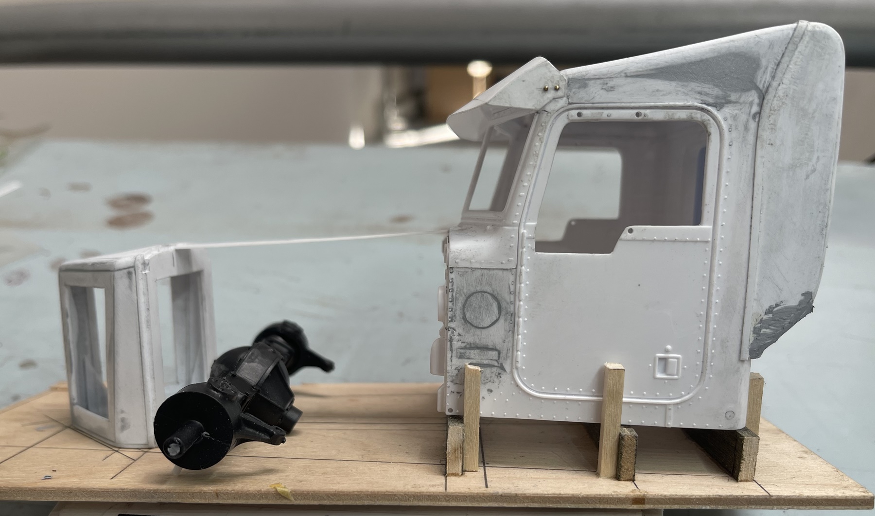
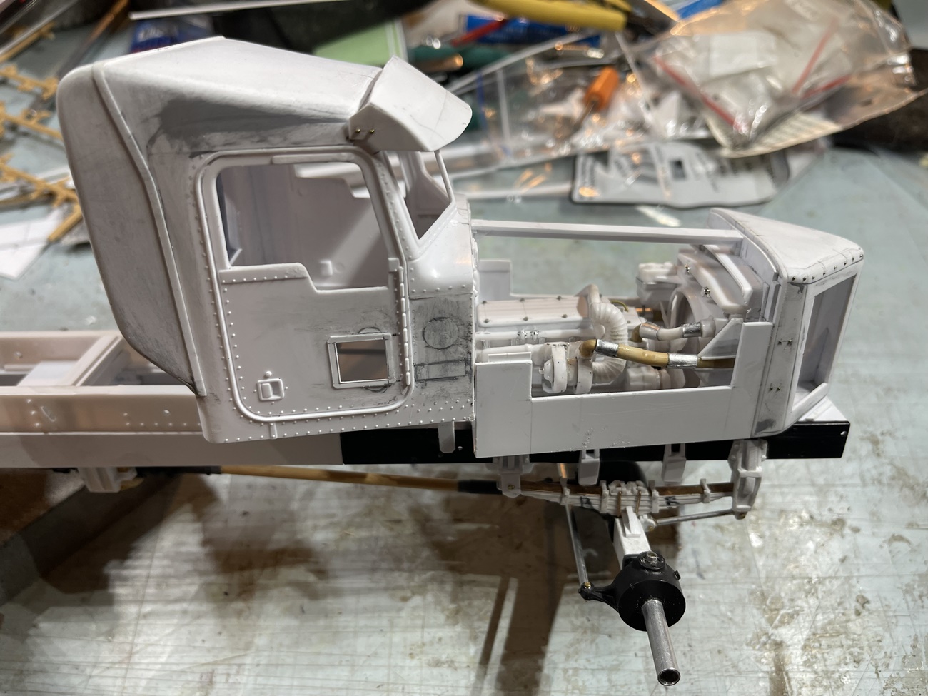
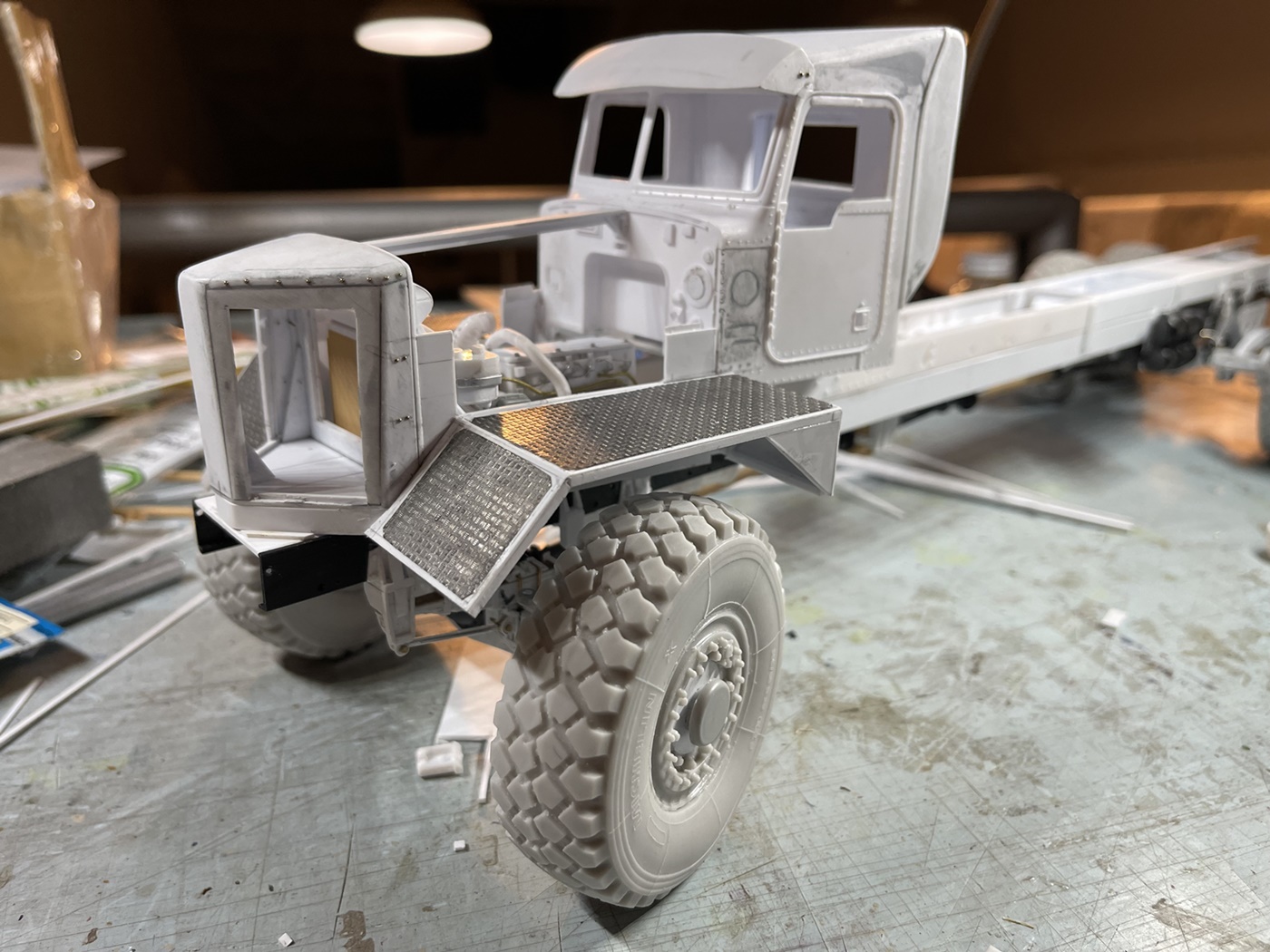
There is plenty going on here - the doors were cut to look like a modern KW, the lower window on the passenger side re-cut to look like the KW version, and the rear and top of the cab reshaped to match the KW.

The visor was a PITA and too a lot of thought and time to resolve. The Peterbilt base cab has a “V” shaped window, and while not completely flat, the KW does not look like a “V”. So, in order to create the illusion of a flatter window, the visor has a long flat curve on the lower edge which when viewed downplays the “V” shape, while retaining the basic look of the actual part.

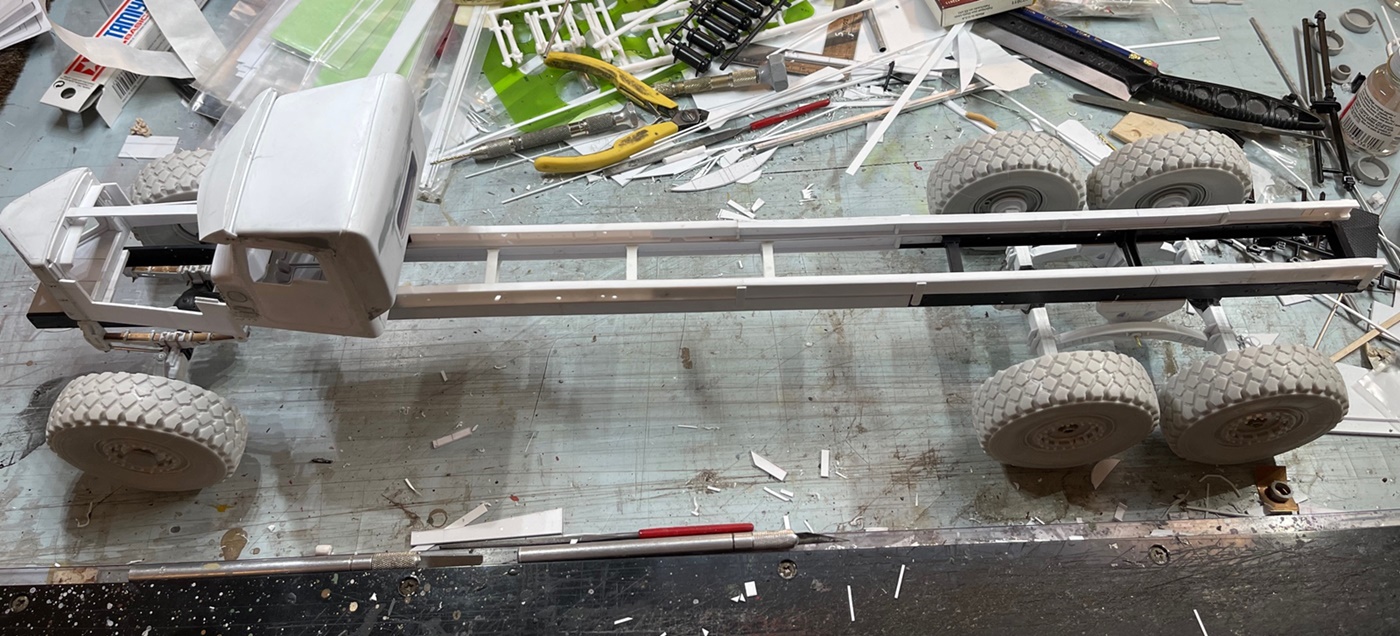
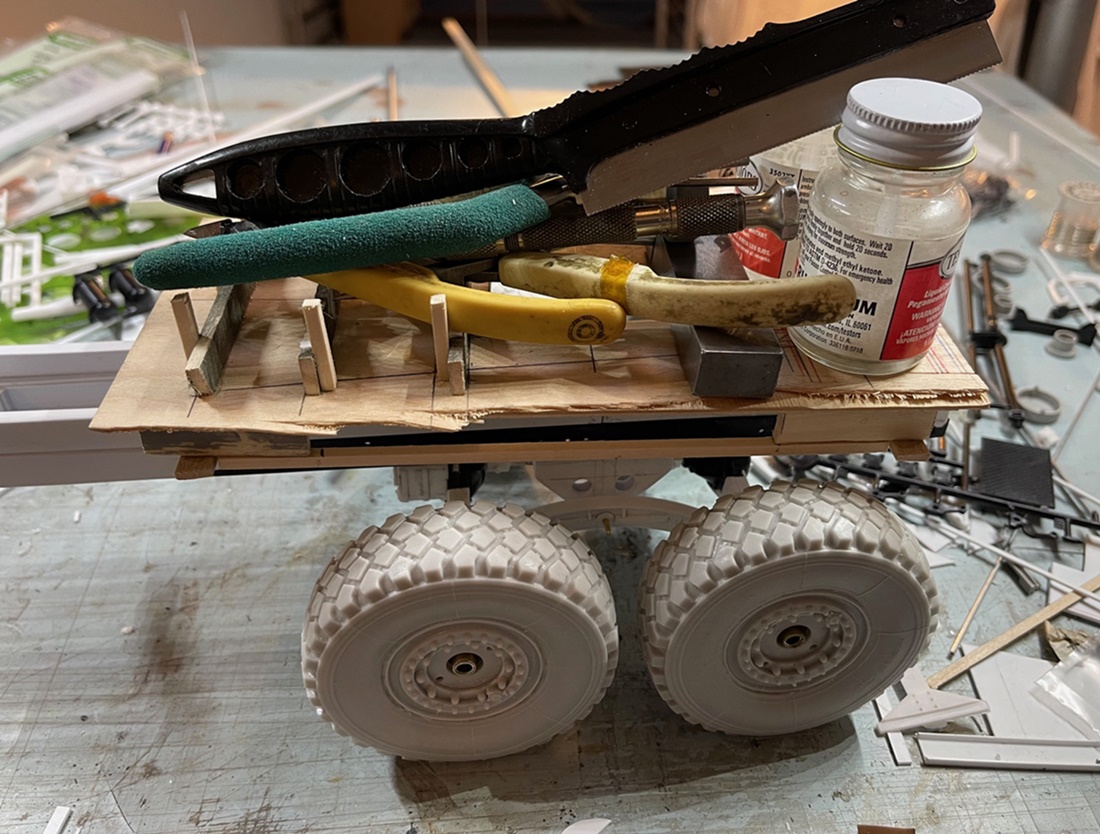
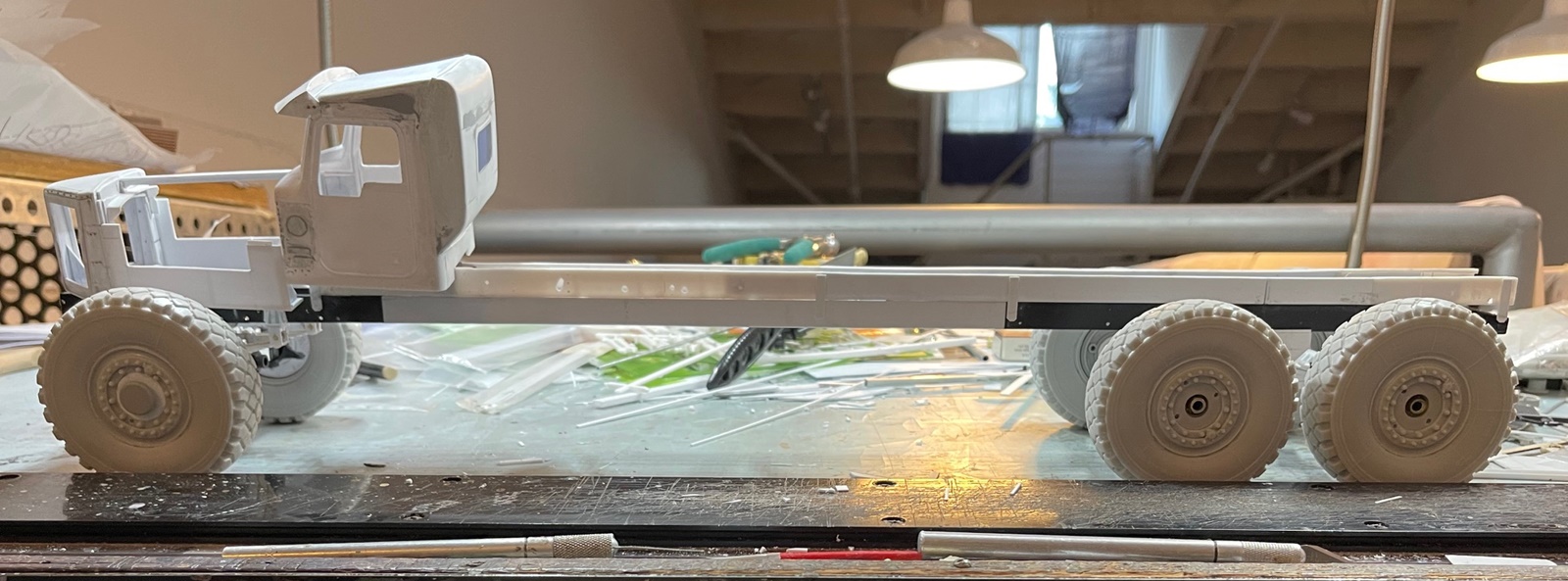
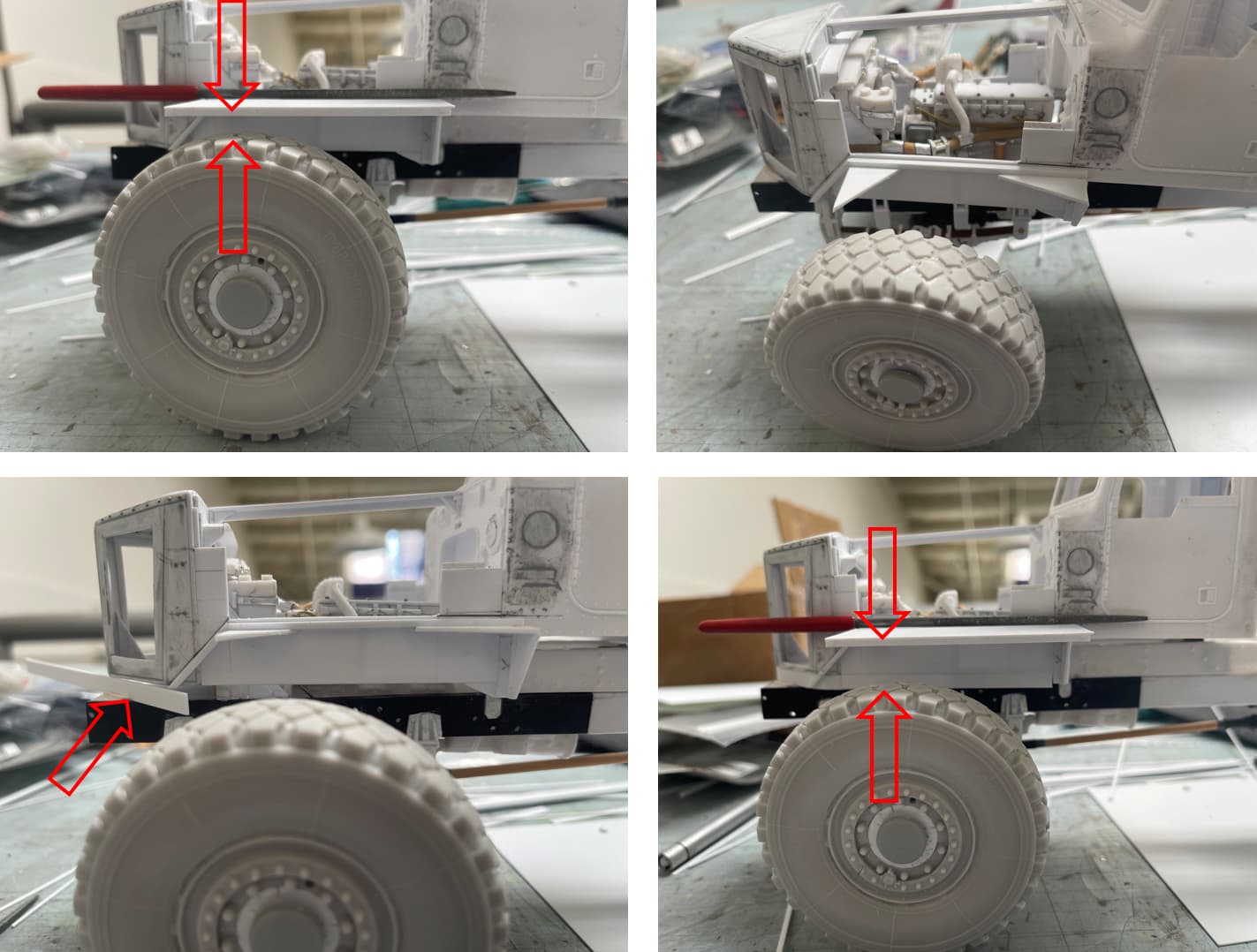
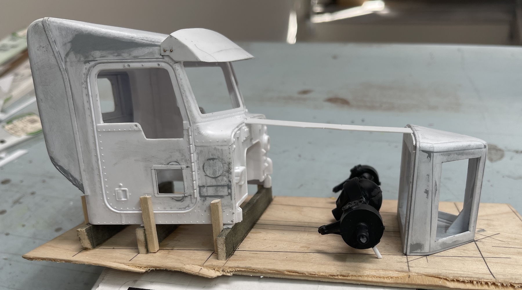
Another challenge is that this is big, and the hood nothing like a normal truck. To address this I made up a jig with the overall shape drawn onto it. As this truck uses a partial twin rail chassis, the cab sits higher than where the hood rests, so it’s elevated.

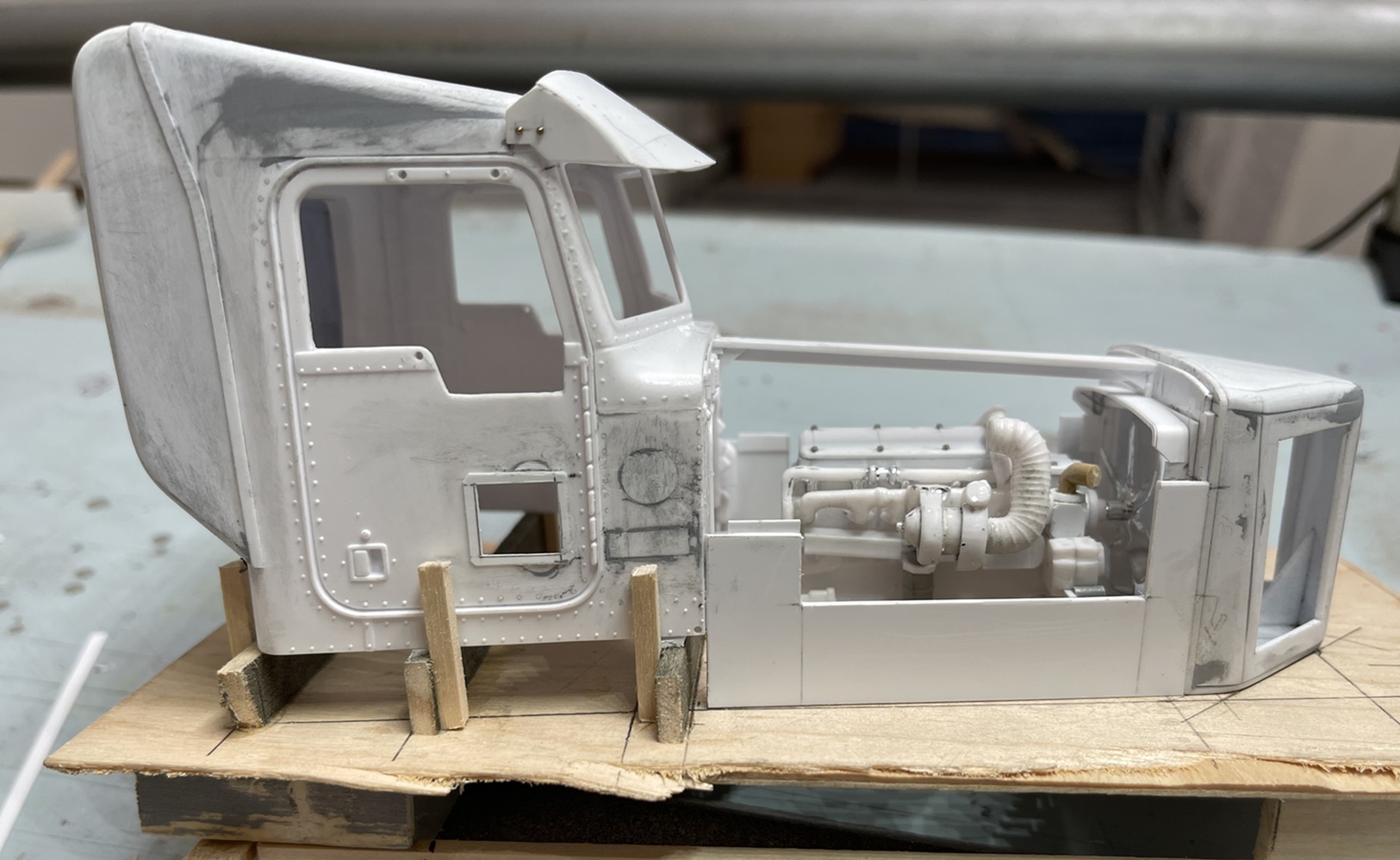
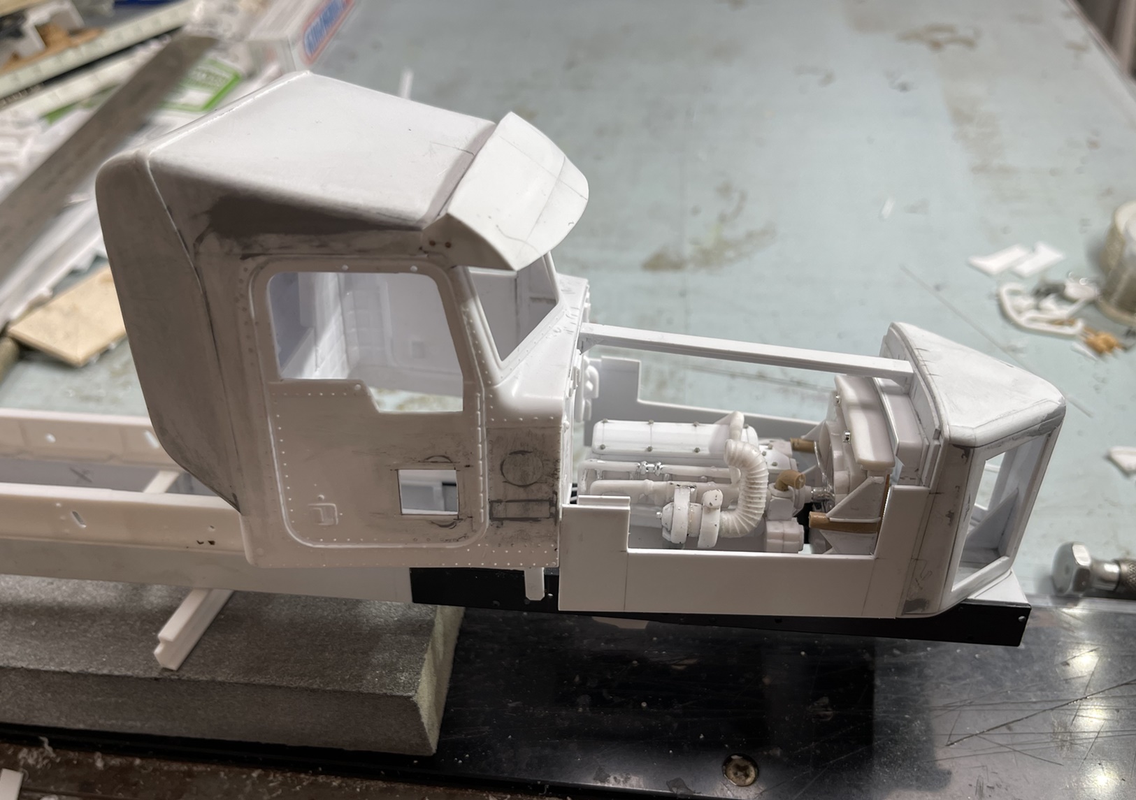
Ok, a guy could go on and on - but won’t. Following the cab, I made the basic nose - which is almost exactly 1/4" lower than the sil that the hood rest on below the windshield - oh - again sorry!! too many words! :smile:

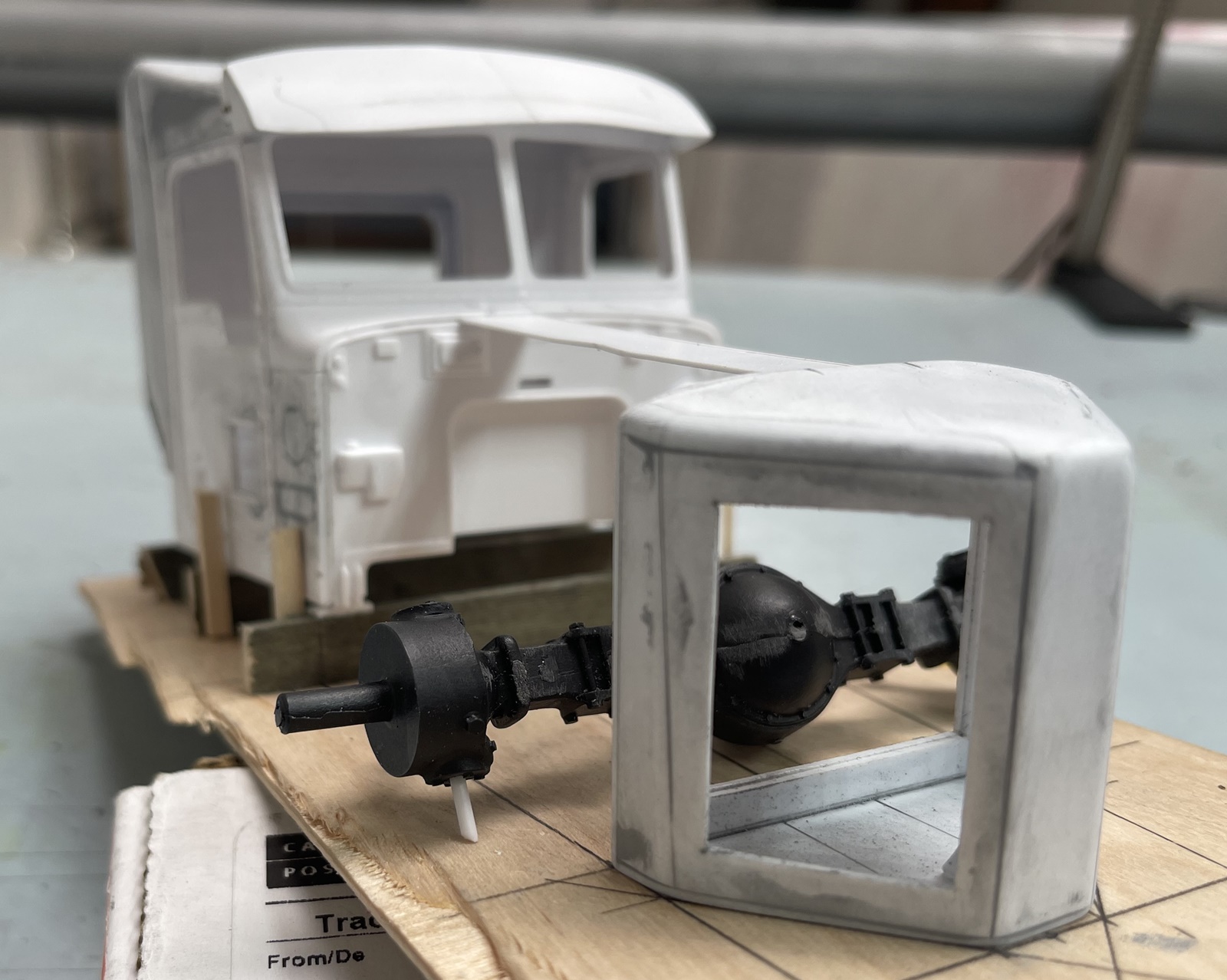
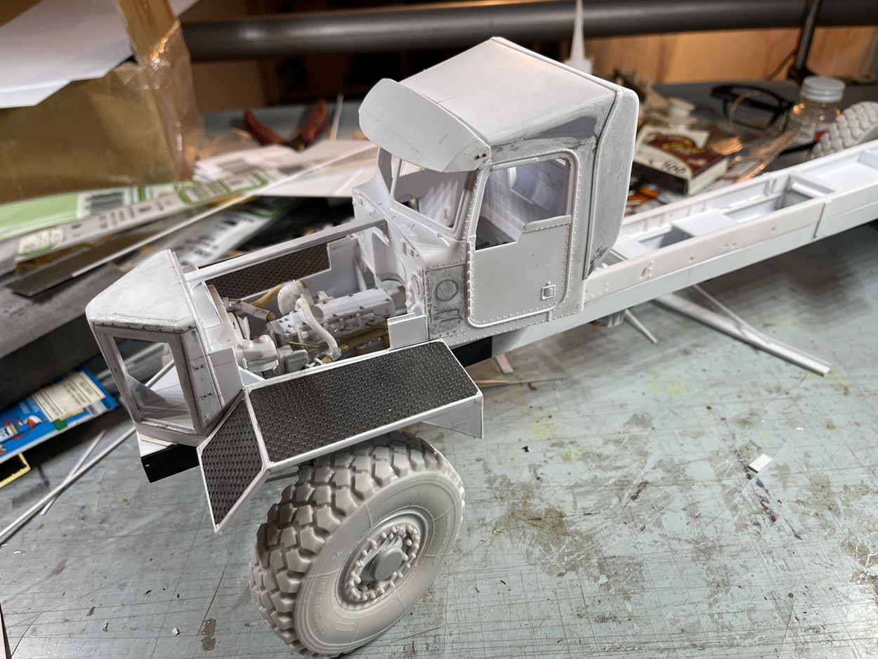
Another real challenge to make! that nose!!! :sweat: :sweat: :smile: (oh, and the visor does not look this wonky - an optical illusion)

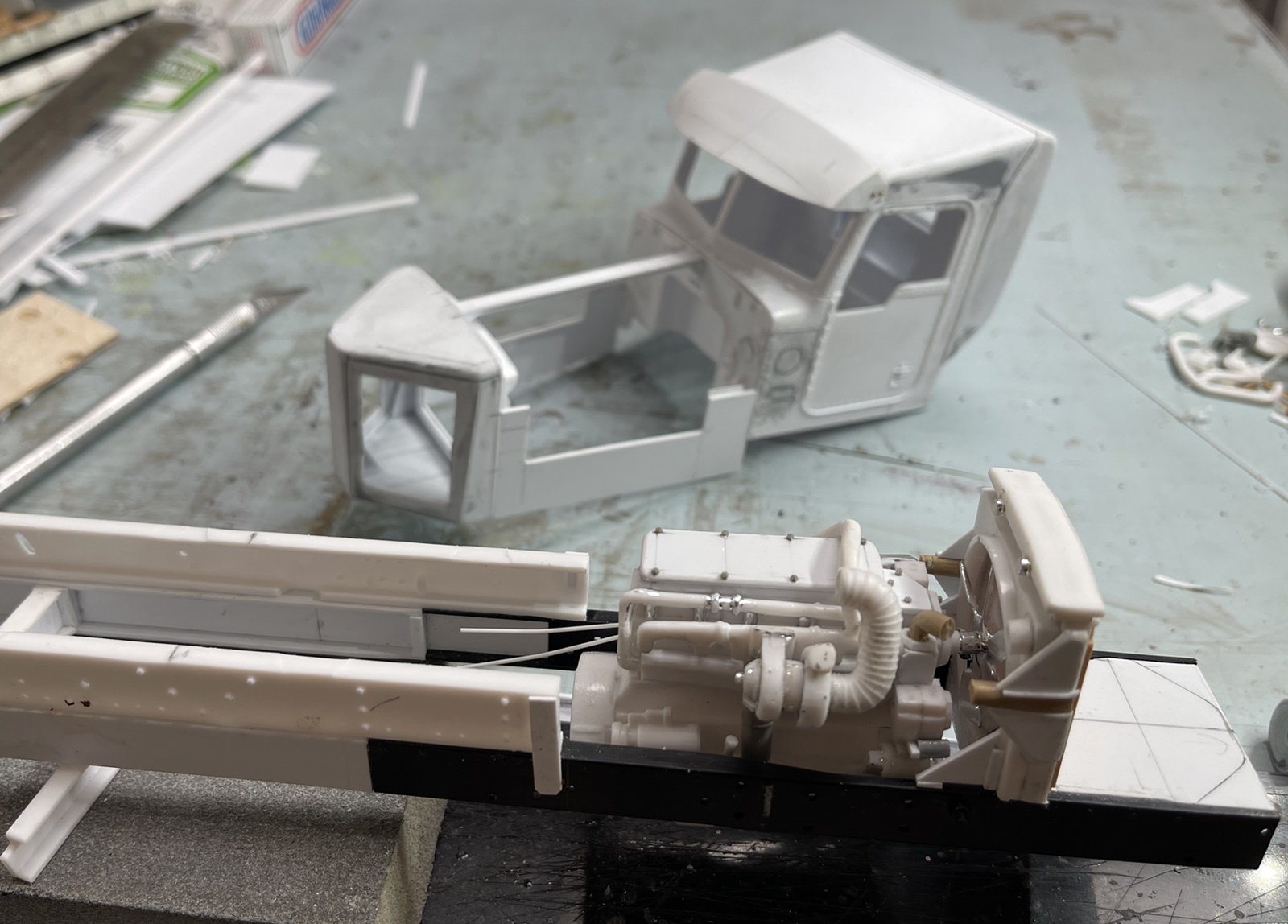
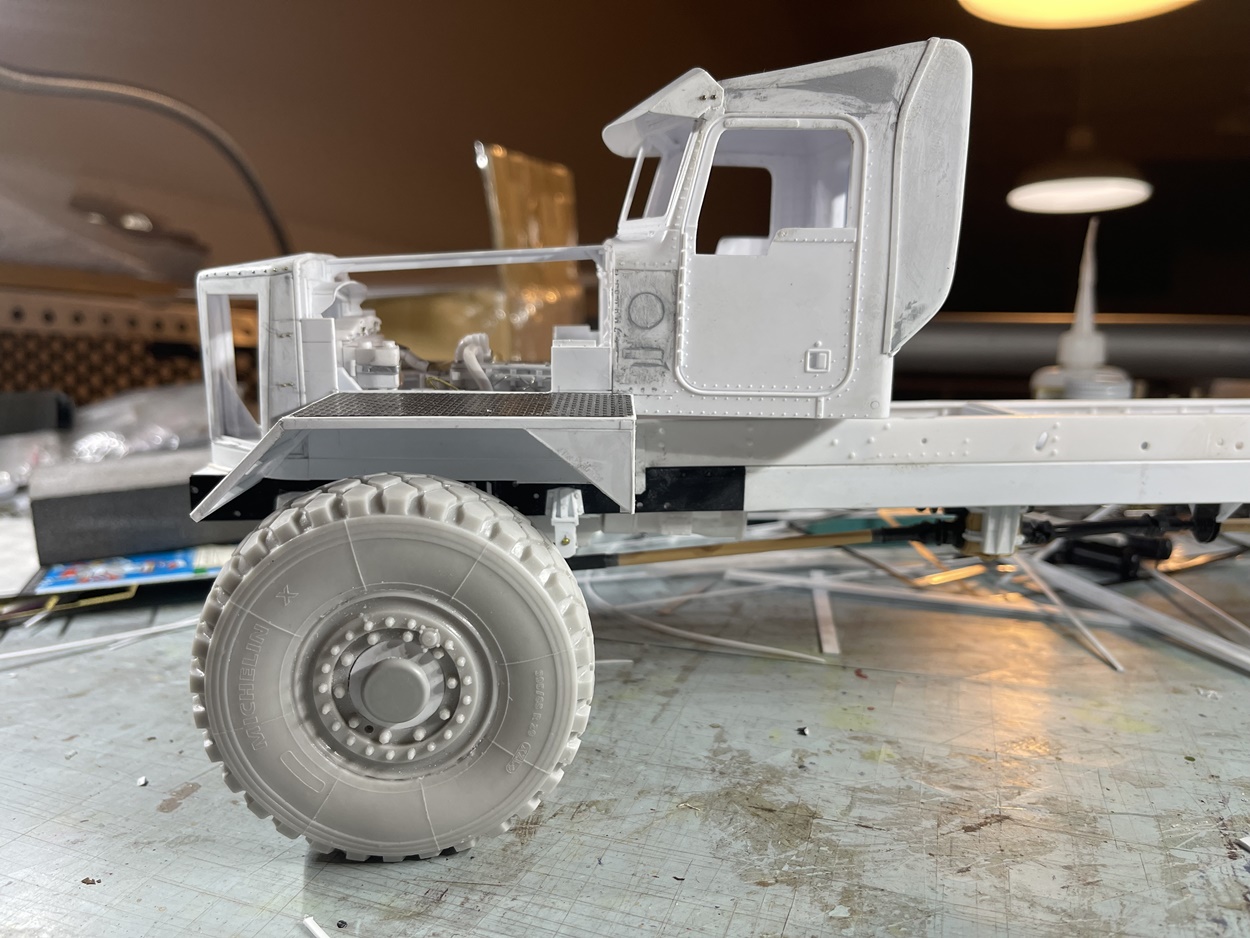
And for a basic comparison:

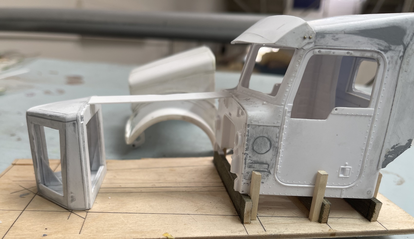
In the background is a hood I made and didn’t use for a Peterbilt 348 - and you can see it’s steep slope and comparatively short length. The 963 hood does not tilt and is instead hinged in the middle.

So, on we go - thanks for having a look -

Cheers, Merry Christmas, and happy model building!

Nick

11 Likes

Dude! Grabbing my White Russian and sitting back to enjoy.

Merry Christmas.

3 Likes

Nice work Nick - I’ll be watching this one.
Best of the season to you and yours.

2 Likes

Yeah man, I’m on board with this one.

Looks like RC Airplane wheels, maybe
https://www.motionrc.com/collections/main-wheels?filters%5Bcustom_fields.Wheel_Diameter%5D%5B0%5D=75mm%20To%2099mm%20(3%22%20To%203.9%22)&filters%5Bcustom_fields.Wheel_Diameter%5D%5B1%5D=50mm%20To%2074mm%20(2%22%20To%202.9%22)

2 Likes

Oh yes, yes, yes, this will be epic! Definitely settled in and watching for updates :face_with_monocle:

Best wishes from the antipodes mate.

Cheers, D

1 Like

That’s one big beast!

Jim

1 Like

Merry Christmas Nick!
Great start on this and I will happily following the “963” into 2024!

cheers
Michael

1 Like

Hi gents,

Glad you have some interest in this project - as a few of you have noted, it will indeed be pretty big - at 23.5" in length! sheesh - and the tires, 3" in diameter. Thanks for the tip KSO, wish I’d have been aware of those earlier - but, the damage is done - big, expensive resin tires and wheels are on their way… :face_with_spiral_eyes:

But, as they are not here yet, I’ve stuck with working on the cab. While I don’t have many detailed drawings of this, I do have one side view that I scaled. And, have a few pictures that show glimpses of the motor, which as it turns out is a Cummins ISX 15, and lots of other photos, which I am relying on to pull this off!.

The donor motor for this is from an old 1/25 scale Kenworth kit, which happily appears to be a Cummins engine that has the same general form as the newer one. But, the top of the engine and most of the front dress is wrong, and it does not have an intercooler for the turbo. So, I did what I could to build those parts up. Which led to other changes, like adding the never to be seen intercooler and adapting the inside of the “nose” to allow for a clean fit. Then I realized that while the hood on this is giant, I wasn’t sure if the air intake assembly would fit between it and the top of the engine. To address this, I cut an opening into my jig for testing:

Happily, there appears to be plenty of room for the ductwork. One pipe will project upward from the turbocharger (you can see the flex tube part), then head toward the cab, and then split off to the left and right side of the truck - easy, right? :smile: The ductwork will emerge from the engine bay, through the sides of the hood, just ahead of the duct holes I filled on the donor cab (you can see the circular putty ring on each side). Big air cleaners will eventually be mounted on the front fenders.

I also got going on the chassis frame rails. This is also oversized - as this truck uses stacked frame rails, which run most of the length of the truck, with the second rails stopping just before the engine:

This frame was a challenge - just keeping it square was a headache. As I expected this to be a handful, I took a very slow and deliberate approach. First cutting kit frames up then filling in segments with several sections of various widths of cut styrene. And on an on - just imagine cutting relatively long lengths of .040" styrene and keeping the cuts generally clean - no fun! then do it twice! :sweat: :sweat:

I added a few stiffeners - at the ends, and along the mid section where I am guessing other things, like transfer case, rear suspension and so on will eventually go. Even otherwise easy steps, like mounting the cab, required some head scratching! It turns out the cab sits atop the second frame rail, while the “nose” sits on the lower rail. You can see the plate in front of the radiator, which sits flus with the top of the frame rails. My jig includes this, but deciding how to set this up on the rails… :sweat: Above you can see how the intercooler works - lots of evergreen and filed pieces of sprue!

Anyway, on we go - thanks for having a look!

Cheers
Nick

9 Likes

A good update for today! The tires arrived and I have set them up for use. As they are intended for 1/16 scale use, and this is 1/24, some changes were needed. Now, new hubs and spindles added, front and rear. I wanted to get that out of the way so that I could get on with the suspension.

First up was changing the front axle, widening it, and adding a truss:

While this KFS axle is already pretty big, it needed to be made 1/2" wider, and the real axle, made by Axletech includes a built in truss - so, mine is now wider and has a truss!

The next task was to finish up, or at least get the rough work finished on the leaf packs:

Piece of cake… :smile: :smile: well, not exactly :man_facepalming: As far as I can gather, the rear of the leaf pack has an eye, while the front floats - but, the front of the pack also has control arms :sweat: :sweat: if a guy just had a third arm, this could have gone more smoothly - alas, no luck. For the model I used the eye in the back, and kept the front floating. The control arms, at least my control arms, are used to locate the front brackets the proper distance from the axle.

Building the suspension was the obvious first challenge, the second challenge tho might have been harder, which was getting all of this attached to the frame and squared up. I took a methodical approach for this, starting with a thick rectangular sheet of styrene taped to the frame rails, used to set the location of the edges of the first layer of locating pads for the spring pack hangers. Then added the smaller bits used to define the locating pads, then adding various gussets to the hangers themselves, which were also used to get the ride height corrected.

Happily, I have lot of pictures of these components, and while my reference pics are from a few vintages of the truck there was enough info to figure out how to interpolate them to build this.

Finally - I had to look at the build with some tires and the cab:

What you can’t see her is that the frame is a whopping 23.5" long! Which, while true to scale, is a bit of a mess to handle - it’s huge and typically winds up knocking parts off my bench as I move it about :man_facepalming:

That said, it’s coming together. The tires fit as planned, and can be steered. Regarding the body, you can barely see I’ve begun adding really small brass rivets to the nose. But, I ran out of them, and the supplier says they are out of stock - so, will worry about that later -

Cheers, thanks for having a look, and happy New Year!

Nick

10 Likes

I remember that feeling from when I built the 48’ Reefer :rofl:

Awesome progress mate, absolutely loving this one! Best wishes for the New Year celebrations, stay safe and have fun.

Cheers, D

4 Likes

Phenomenal engineered progress on the monster. Those wheels are giving it some serious attitude!

Happy New Year :beer:

2 Likes

Hi guys, and Happy New Year! :sparkles:

@AussieReg D, yes, this is indeed huge - I can only imagine working with that trailer!! Did anything stay on your bench during the build?? :grinning:

@KoSprueone Hi KSO, yes, those tires - are big, and heavy! It was almost impossible to do any real testing until I figured out how to make and install the hubs/spindles/axles… :sweat: :grinning:

Anyway, try I did, and as work starts again tomorrow, well, I guy kept at it.

First up, figuring out the rear end. It’s a big walking beam, mounted on some towers - easy enough? right? well, no.

Without going on and on, the challenge here is that there are pins on opposing sides, that hold the walking beams to the towers - easy - that way this could be built like a saw horse, with the pin running the full width of the chassis - except, it doesn’t do that in real life, because if it did it, it would hit the axle driveshaft. :man_facepalming:

So, I went through my pictures again, with the hope of getting a better idea about how the real version works, and as it turns out, there are gussets on the inside of the towers, supported on a cross member. So, mine has this too! The axles - well, like the front, they have trusses built in, and both diffs have modifications.

Another thing, the walking beams are mounted under the axles!! where are those third and fourth hands??

Here’s how it lays out:

And how much weight will it carry? All of it!

If I had more heavy stuff on the bench, this would easily carry it.

This was built using mostly .040" styrene, with alu and brass tube for spindles, so it’s pretty stout.

Finally, yes, mercifully, it sits on all six! and appears to be fairly level, front to back. As I’ve been building this on an drafting table with a tilt, it’s hard to tell exactly:

While it looks like this is nearly done, it’s not. The rear end still needs a lot of work, and the body has lots of steps,. ladders, tanks, winches and on on! Oh, and the engine and driveline!

Cheers, and thanks for having a look

Nick

9 Likes

Amazing detail in the build and love the approach and problem solving tutorial. That last photo shows perfectly the scale of the task.

cheers
Michael

Hi @cosimodo thanks, Michael. I have pushed aside the thought that this is something of a ridiculous project, as it will hardly fit comfortably on any shelf, but to your comment about the process, it has been a pretty good test in problem solving. There are some parts that despite their scale have some nuance, and, as this is indeed big, whatever gets built needs to be strong enough to support itself.

The resin tires/wheels are pretty heavy. Sitting in place things are fine, but, when you lift the model by the frame rails with them on, you can clearly feel and see the frame twisting. To resolve this, I’m thinking about adding some solid sheet between the frame rails to act like a diaphragm, essentially creating a horizontal shear wall. We’ll see. The suspension attaches to the frame at discrete points, which unhappily also serve as moment arms - so- when the chassis is lifted up, the heavy tires torque the frame, more so in the rear, where four tires are attached to the frame at two points (the towers that connect to the walking beams). Ahh - my coffee is still working!! words words, blah, blah, blah!! :smile:

One way or other, I will try and take some flex out of the frame!

Cheers
Nick

5 Likes

Missed the initial post for this … WOW ---- this will be epic — now thats a genuine working monster truck …

1 Like

:man_lifting_weights: woooooooo000000000OOOOOOOOOW!!! :man_lifting_weights:

Extremely nice! :metal::star_struck:

—mike

2 Likes

Ha @Johnnych01 well, it’s certainly a monster in the works! Sorry to hear about your arm! hang in there with that!

As for this, well, more details added:

Added front bump stops and more to the engine

And some slow going on the driveline… :man_facepalming: had to reset the transfer case a couple of times :sweat: and the carrier bearings, happily, they are able to rest on some cross members I installed early on -

And, got the cab mounts set, and well, a guy added details to this side of the engine…new to be seen again! :smile:

On we go,

Cheers
Nick

11 Likes

Dam Nick , that’s beautifully engineered !!! … and exquisitely scratched and rendered in scale !!!
No miniaturist verbiage used here !!!

4 Likes

@Cheyenne, Glenn, you’re right, this clearly is NOT a miniature!! :smile:

It is actually a highly detailed, accurate representation of…uh, what? that doesn’t look right:

Uh, wait, what? hmmmm…this is not a low rider - what in the heck is wrong with the fenders??? ahh, nobody will notice…yes, they will. Shoot - what to do about this (upper left). Giant tire, limited suspension travel and whatnot, no big deal…that is not right.

So, the testing began (lower left) how could I pick up some height? what’s wrong here??? well - after rescaling my one line drawing - I figured out that I spaced on a dimension, just forgot about 3/16"…perfect.

Not any more, as shown in the lower right. It now sits at the correct height. I added to the lower portion of the hood area and adjusted the cab mounts, so now it sits where it needs too.

And while I was at it, got after the front fenders in more detail:

This ain’t no miniature - and I’m not kidding…It’s, well, a model of truck! :smile:

After watching my 49ers lose…back to the bench I went, and struggled through this. These fenders, like the rest of the truck, are big and more complicated than they look - oddly shaped, projecting far from the body, and with diamond plate decking - in reality, the whole fender is diamond plate…ok, yes, I settled for an alternative! Not done yet, but they are firmly attached to the truck, looking about right, and with NO wobble!

On we go -

Cheers
Nick

7 Likes

Beautiful representation of a molecularly challenged 1/1 scale truck .

Looking great Nick !!!

Niners didn’t need the win for the playoff scenario but yeah it still sucks losing to a division rival .

1 Like