Only discoverd your topic today and read it, love it! Had a radio controlled Graupner ship when I was 17, so allways kept a slight interest in it.
This is fantastic!
And about pictures upside down: if you add 1 picc first, and check that out, you can turn them (if needed) uoside down in your picture folder before uploading them, then once finished turn them back as they were for watching on your ipad. Happens to me to, don’t have an ipad but took pictures with my phone and stored them on my laptop.
Thanks for the tip, it was too late last night to mess about. The iPad camera is pretty good but drives me nuts on this site only. Everywhere else it’s fine
Well from where I am the last photo is definitely the right way up 

5 Likes
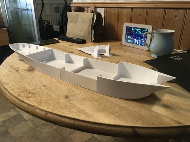
Another 11 hour print and I have a bow. Now I have a possible LCT(2). Need another section like the one just behind the bow to make LCT(3). Decks have been designed for the midships sections today, a set of those will be printed next to test them. The sectioned appear to fit pretty well.image|640x480
3 Likes
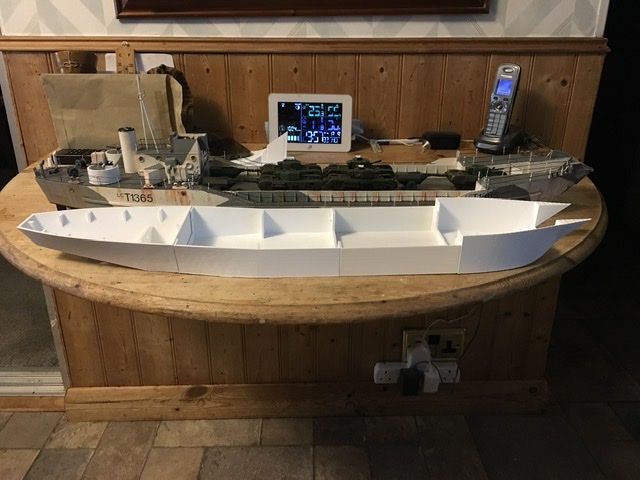
Just to compare sizes LCT(2) against LCT(4)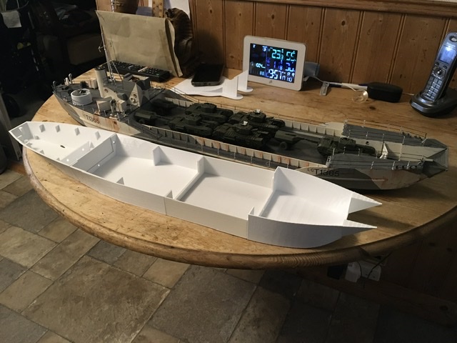
4 Likes
Terrific work.
1 Like
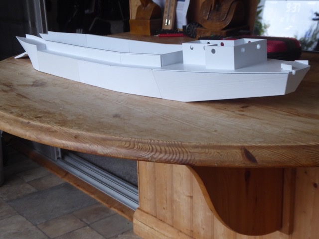
3D printed, set up as LCT(2). Aft tank deck insert ready to print, bow internals are tricky shape but design started. Good news is I can get batteries in the sides under the tank deck. Might build this as a 2 but will have to add a third shaft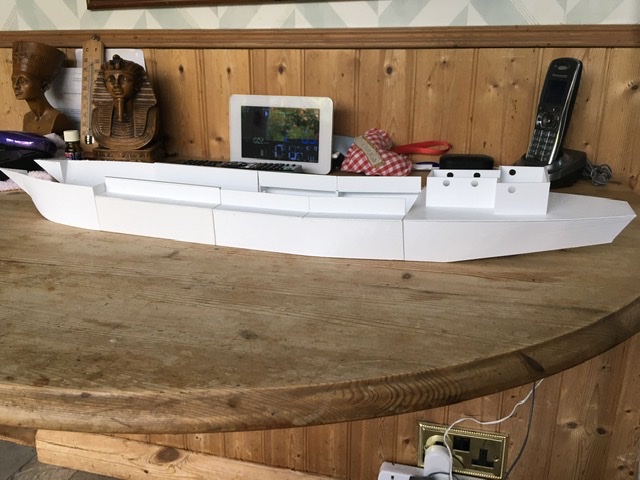
4 Likes
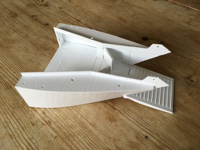
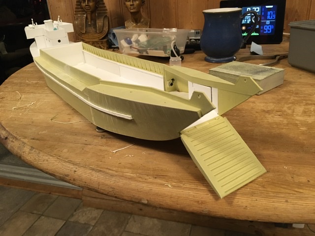
Not been able to do much over the last two weeks, but I have printed the remaining tank deck pieces and ramp and corrected a couple of mistakes. The worst mistake was the bow where two lofts join, the sections were wrong.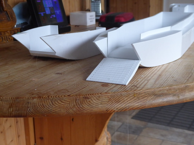
The wrong one on the left.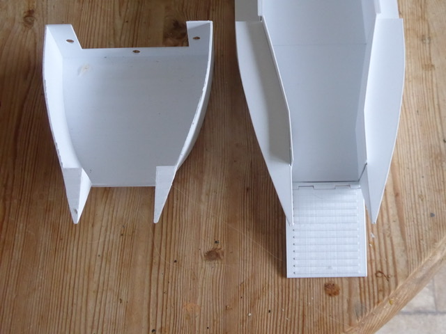
The error shows up better from above, the left print is pinched in where the deck stops. Printed the ramp and fitted using a piece of filament for the hinge.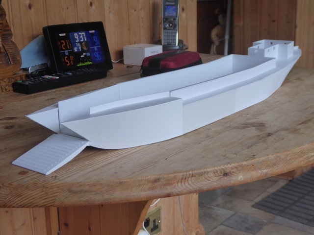
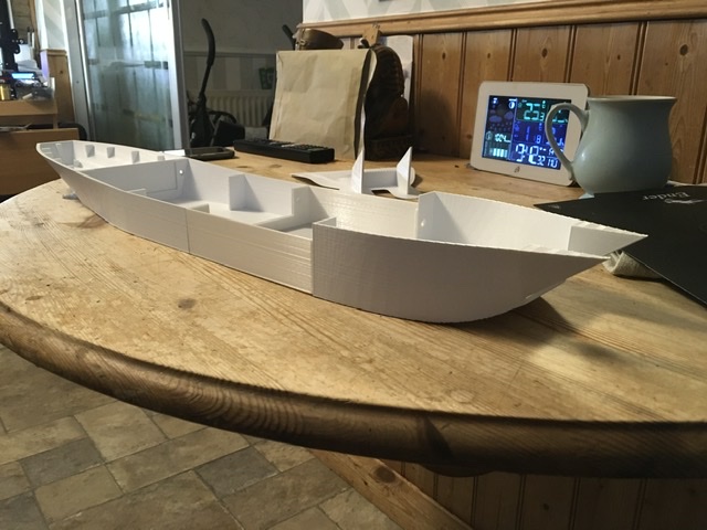
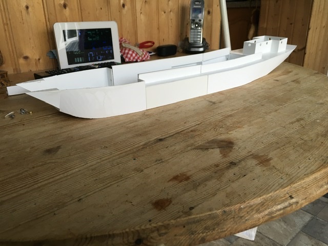
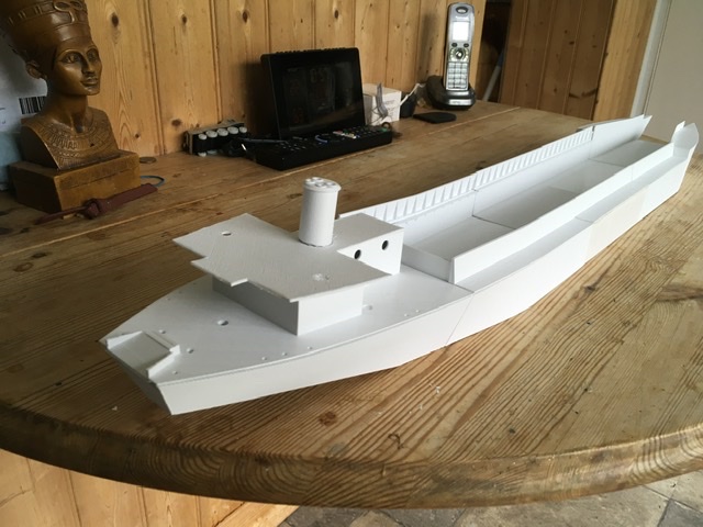
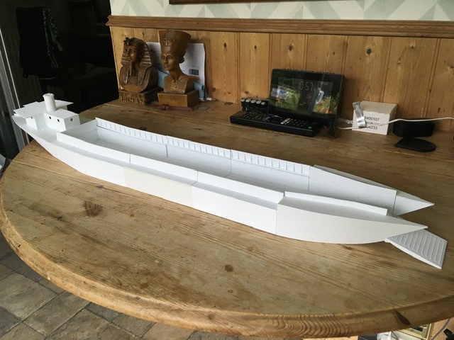
Sections all bolted together showing the hull shape for an LCT(2).
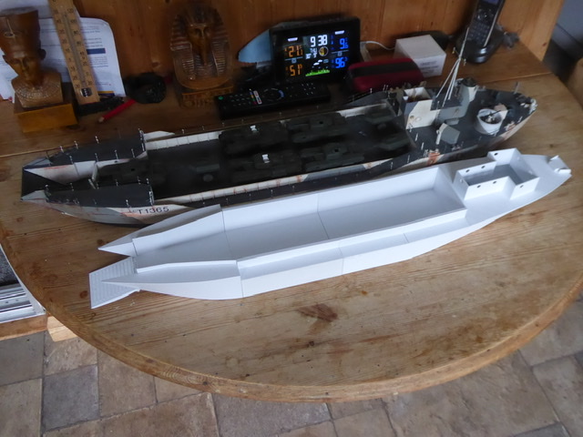
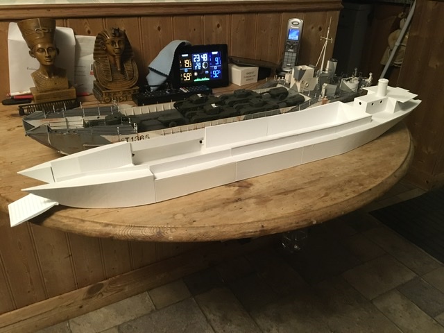
Finally, comparison between LCT(2) on the right and LCT(4) showing the increased beam and length of the 4. The reduced draught isn’t yet apparent. The 4 also carries the tank deck higher in the hull
7 Likes
I went to Portsmouth to look at LCT7074 a week or so ago, came back and scrapped half of the LCT(3). I decided that the gunwhales had to be changed, I had glued then in place and damaged the hull sections trying to get them apart. (Cyano works on PLA) Reprinted all the midships sections, the bow needs minor mods as does the stern. 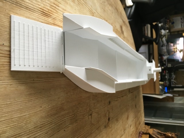
New inner bow needed without side bulkheads
New quarterdeck with built in anchor bed and part location holes added
New gunwhales, NOT yet glued in place with supporting ribs. Lower tank deck sections with internal flange at the top
 the old gunwhales just don’t cut it
5 Likes
Getting good solid references late in a project sucks …
2 Likes
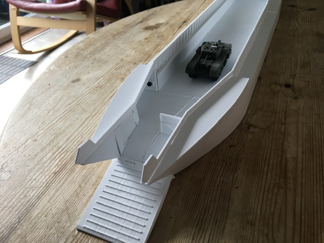
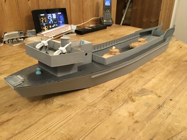
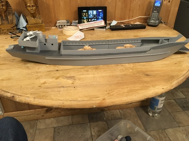
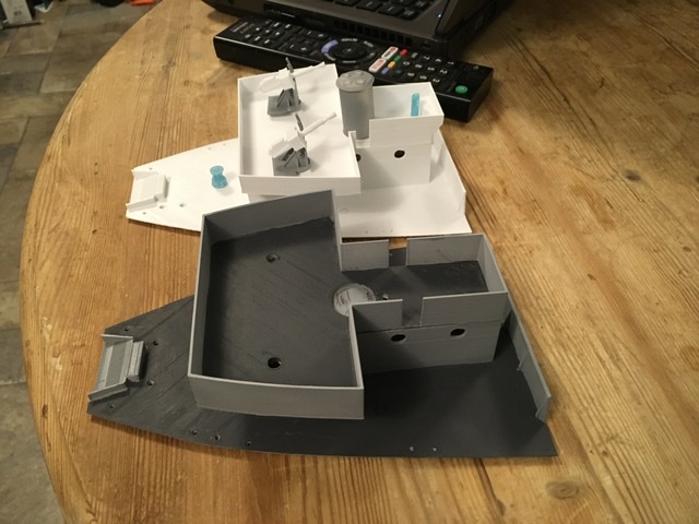
Now have all prints for the main structure of the LCT(3). These photos show a dry assembly for the proposed model, an early LCT(3) for Operation Husky, 1943 invasion of Sicily. The bow needs some small mods to improve fit and to build the breakwaters into the hull print.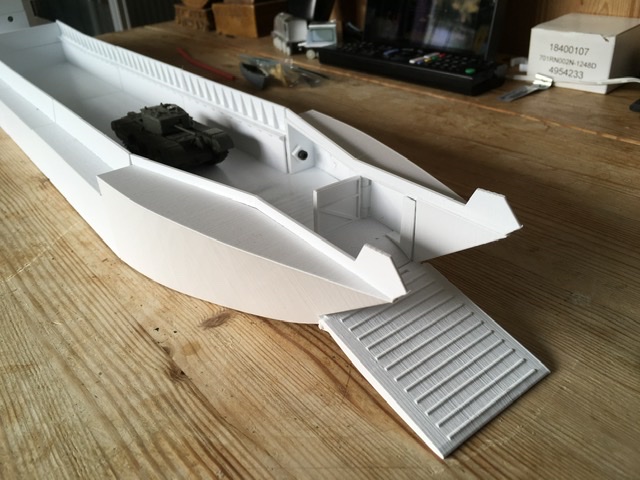 Bow with port watertight door closed. Bolt will be hidden by the fresh water tank. Bow profile needs cutting away at the tip both sides,
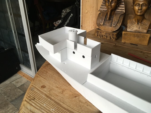 New gun deck print with bridge and gun protection incorporated. This is a different shape from the later 7000 series
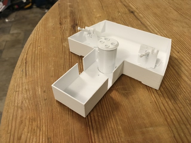
 Gun deck and revised quarter deck with locations for deck fittings
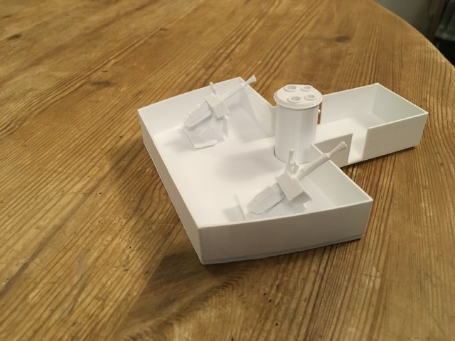
 A closer view showing holes for capstan, stoppers and vents
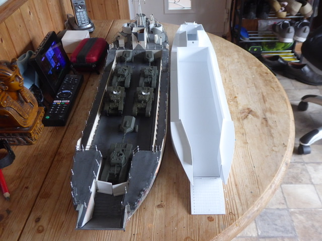
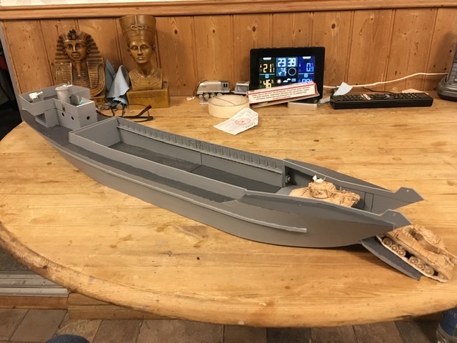
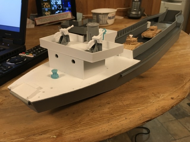
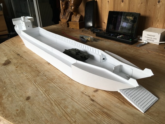 Overall view of the whole dry assembly. Tank is Airfix Churchill, slightly underscale but not far out. You can see how low the tank deck sits compared with the LCT4
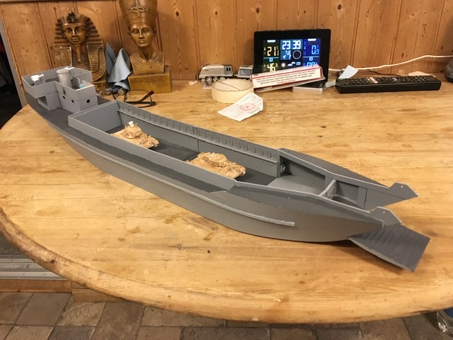
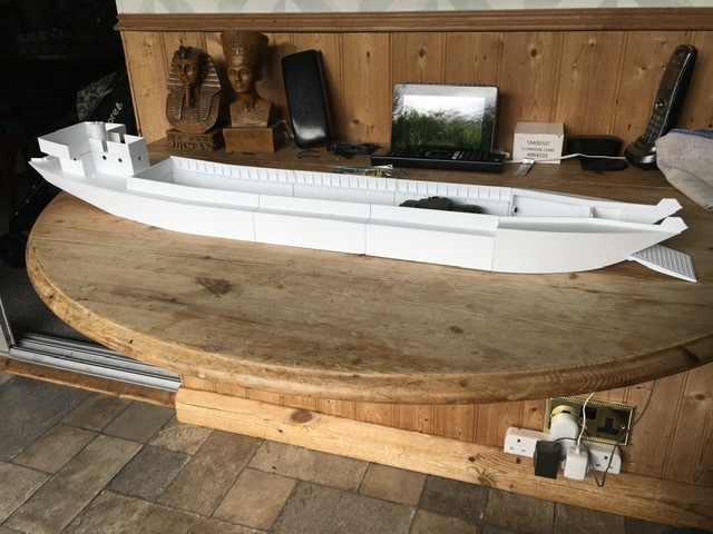 side view, actually, not an unattractive little ship!
 Starboard WT door open. Starboard bolt will be hidden by washing facilities and heads.
4 Likes
Bit more work on the printed LCT. I was never happy with the bow assembly, the outer wasn’t too bad, the inner difficult to assemble accurately. So redesign and then prints to prove fit
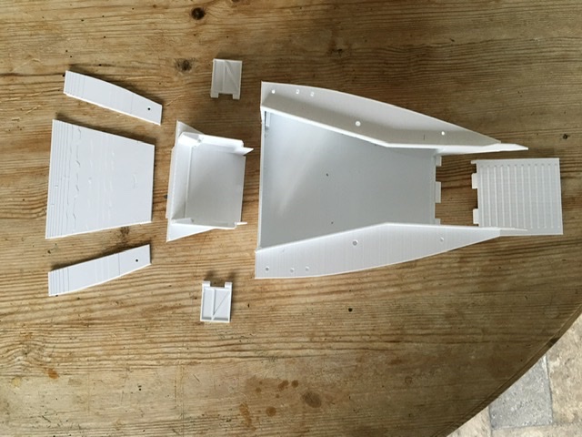
This also allows fitting of a working ramp and watertight doors, impossible in the first one.
I also altered the stern and quarterdeck to add detail and improve fit, also adding an LCT2 option with three shafts. But the time I had these printed I had enough bits for an LCT2. As the 2 was introduced early in the war, before Oerlikons were widely available they carried Vickers 2 pdr
Pom-Pom guns, these have been drawn and the first pair printed

These are first guns dry assembled on early bridge.
6 Likes
Sections joined using Milliput to hide joins, two coats of filler primer, rubbed down between coats and fender strakes added.
LCT(2) 1/72 scale
Bow ramp lowered but WT doors shut
WT doors open
Starting to use SLA printing using resin, first test prints, binnacle and capstan
New capstan is much better than FDM version
6 Likes
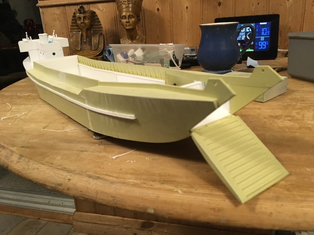
Paint, well first coat anyway. Amazing how it lifts a model
Printed two tanks, a Matilda and a Valentine gave them a wash of brown need paint now
Side view, I like the shape
Time to start adding detail
Playing, tanks unloading, Valentine leading. Planning to show the ship as in early to mid 1942 in the Med, so Desert camouflaged tanks, and with Matildas being phased out, mixed units are possible.
6 Likes
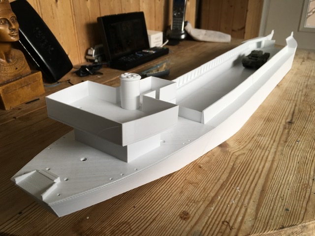
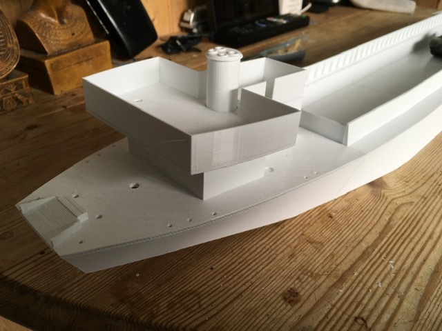
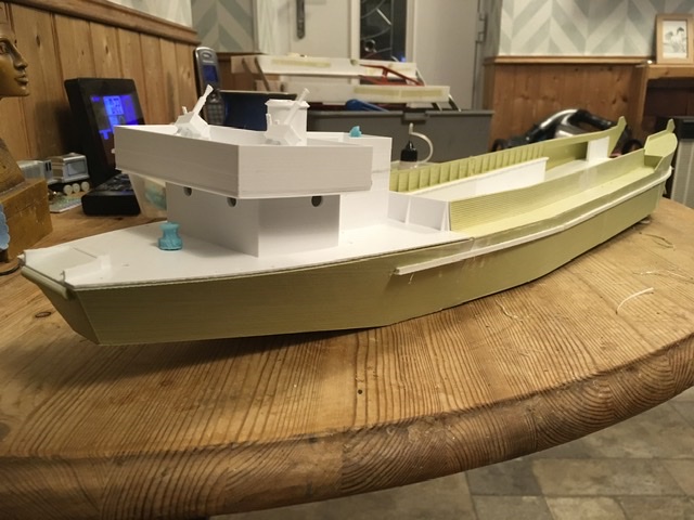
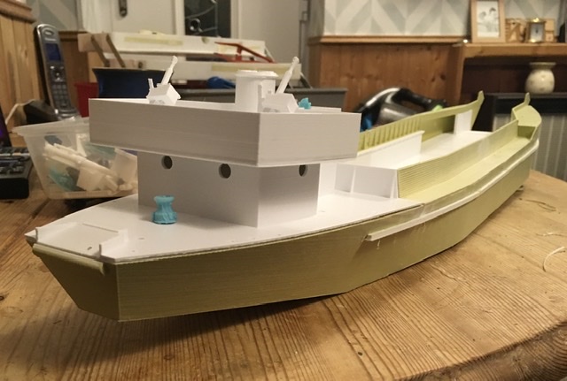
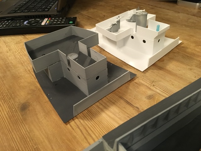
Screwup time. I made the bridge on the LCT(2) from LCT(3) 7000 series plans. Big mistake, the 2 had the funnel and gun platform about 3 ft further forward, eliminating the overhang behind the bridge. Only found when positioning detail parts and something didn’t look right
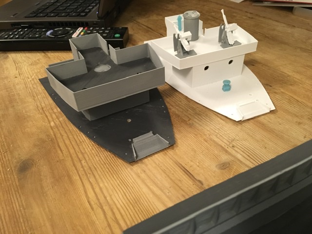
Wrong bridge structure in grey from aft
From starboard side
From front
Correct on the ship
Wrong one on the ship, the overhang was one give away, the LCT(2) doesn’t have it.
3 Likes
Nice save Andrew although it was already looking great before! This is some marathon (I just re-read your opening post) so keep up the stamina 
1 Like
Starting on detail now. Some can be lifted straight from LCT(4) builds, some needs to be modified.

Stern is where the main work is.
Not too much on the bow, need to make some roller fairleads and Panama fairleads for the forward anchor


Bridge needs fitting out as well. A thought occurred that as this is a three engine ship it should have at least three main exhausts at the top of the funnel, plus the auxiliary ones.
7 Likes
Quiet week last week in isolation with the dreaded Lurgi. With materials and time to hand I decided to fit the three shafts.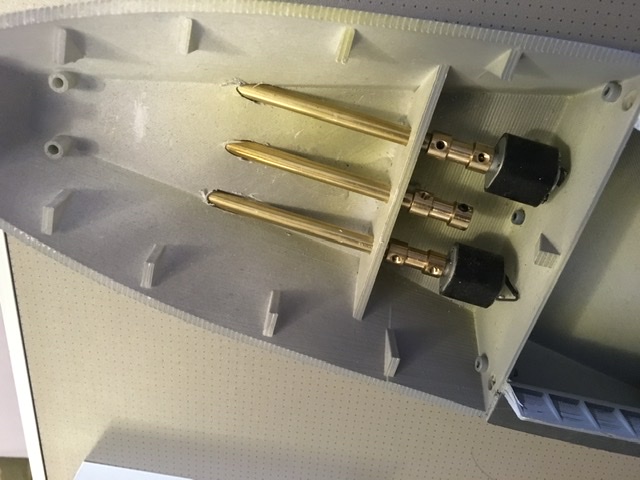
Left the starboard one as I first intended to fit it but it just looks wrong. The shafts should be more like the centre and port shafts but with supporting A- brackets.
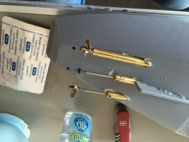
First attempt using oilite bushes in the A-bracket. Not happy, the brackets look clumsy.
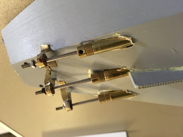
Next attempt using 3mm brass tube in the bracket. The slimmer bracket looks much better, going with this. While I had the 3mm brass tube, printed and made up rudder assemblies. Rudders are scale size and shape, I think they will be ok

Just got to glue all that together now, I have temporarily mislaid a motor and third prop is on order.
7 Likes
I keep coming back to read here, can’t wait to see these fully finished.
Loved those first pictures of the loaded LCT’s already, and now with all that extra detailing… 
2 Likes
Why you need two 3D printers.
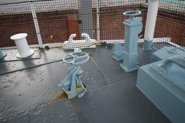
First image is capstan controls on LCT7074 in Portsmouth, looking from the port side. Right is the throttle, behind it is the gear lever, left is the brake. The operating shaft for the brake is missing
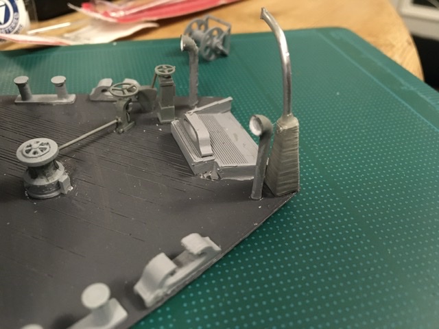
Resin prints for the controls above and the capstan from the starboard side
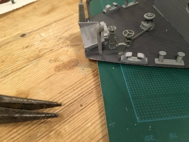
Controls and capstan from port side. Compare the anchor davit base with the finish and detail on the controls and capstan. Most impressed that I designed in the rivets on the capstan brake band and they are visible! Does mean I might have to change the davit base even though at normal viewing distance you can’t see that finish.
5 Likes