Hi everybody,
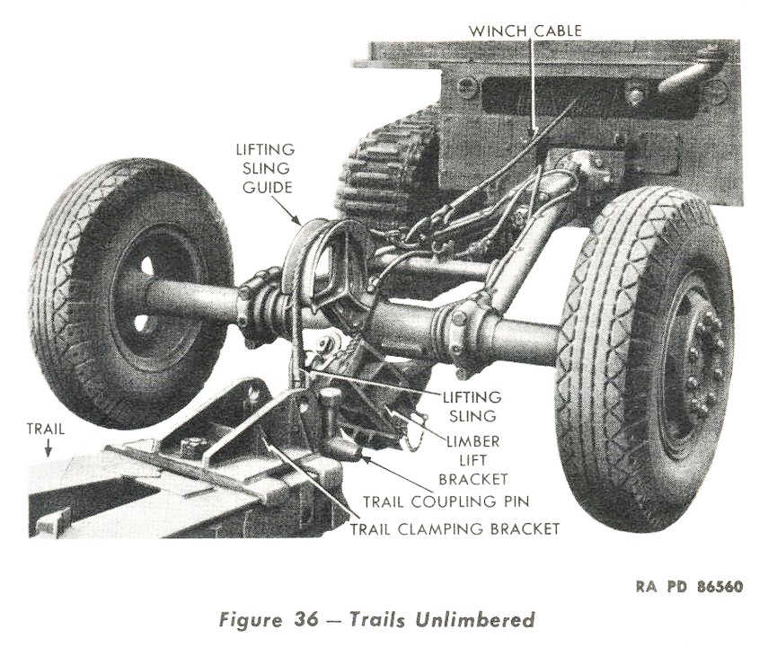
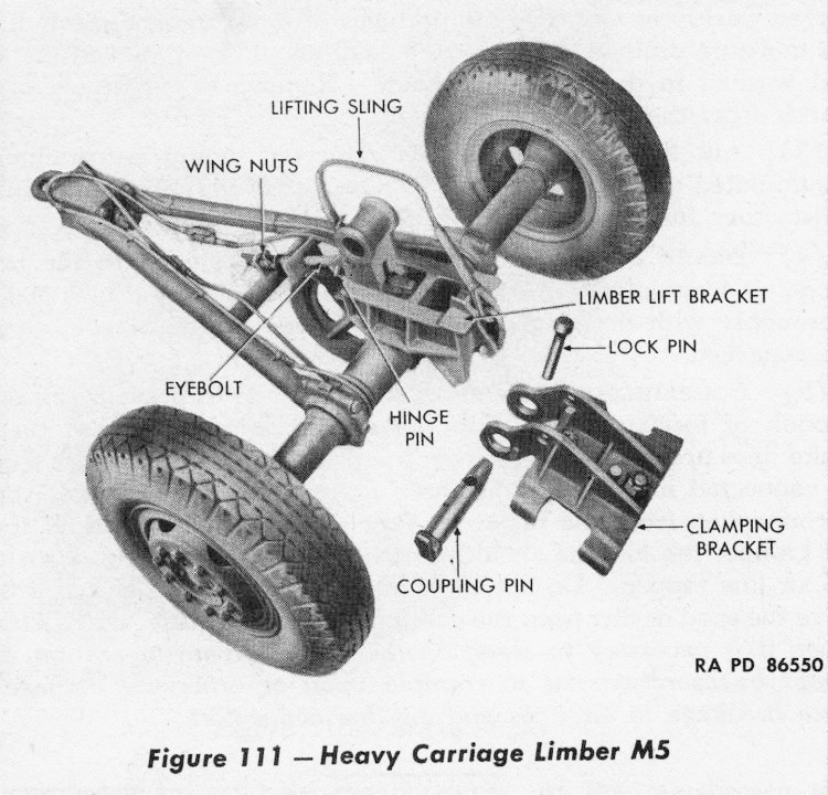
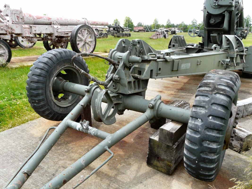
I bought AFV Club’s M59 kit in late 1994 and now at long last started building it. As always, the net shows lots of details that can/must be corrected or added, and among them is the “Lifting Sling” at the front of the M5 Limber Lift Bracket. Although I have the gun’s TM, I just can’t find an illustration that shows just where exactly this wire rope is attached to the bracket: I have a notion that there’s a hollow in the bracket’s front, while in one photo it seems like the rope is being held by the bolt that also holds the “Eye Bolt”, - I just can’t make out for sure.
So, please help!

THANK YOU, Henri Pierre!
It’s always amazing what you find in the depths of the web, where other people seem to be blind …
Peter
You’re welcome Peter ![]() In fact I didn’t dig that deep to find these …
In fact I didn’t dig that deep to find these …
H.P.
And here’s the next question:
AFV Club molded the lunette (the towing eye) on an axle with square cross section; as a non-expert, I had expected that to be able to rotate in its bearing - think potholes. Or was the play in the towing hook considered sufficient?
The lunette eye should be a torus, not a cylindrical ring.
KL
1 Like
The lunette eye is a torus alright, but the shaft that it’s attached to runs through a “box” that forms the apex of the drawbar, and it is held in there by a hexhead nut at its other end. And the stretch inside the box has a square cross section so the lunette can’t rotate - not on the prototype, either?
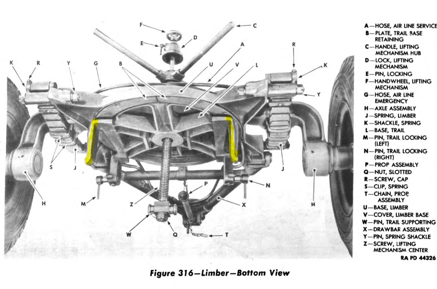
OK, this is the M2 limber:
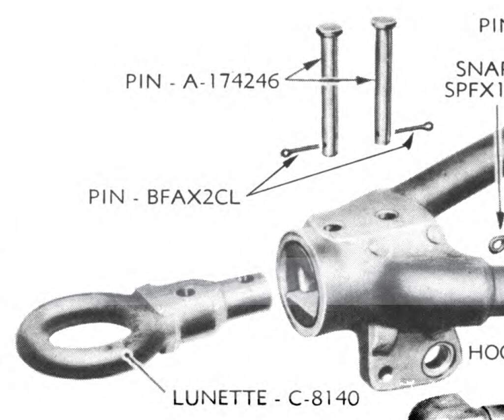
It looks like the stem is two diameters with flats machined on the larger diameter to prevent spinning.
On the M5 limber the lunette was similar in principle but used keys (probably Woodruff) to prevent rotation.
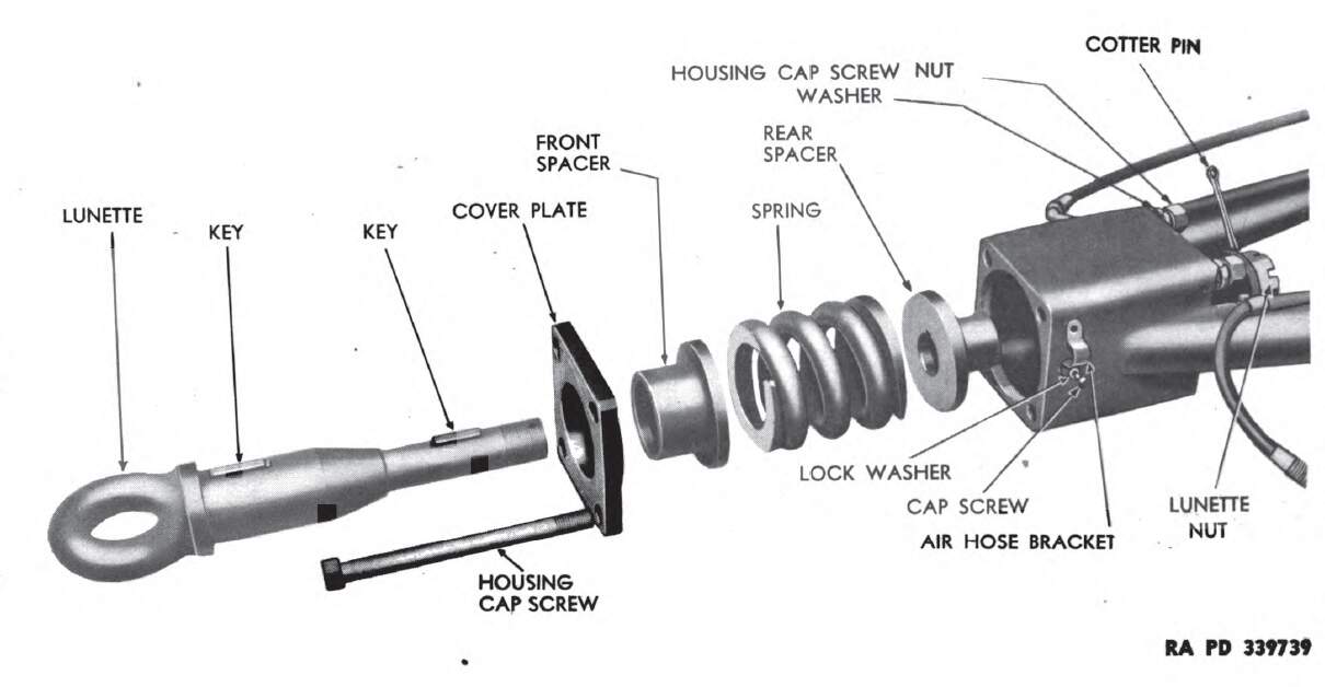
The kit simplified things by using a square shaft. No issue unless you are planning to show it disassembled.
KL
2 Likes
The lunette being a torus will allow a certain amount of revolution between it and the pintle (hook) depending on the amount of difference between the cross sectional shape/ size of the hook and the minimum interior diameter of the lunette ( torus ) , said rotation being about the axis of the shaft holding the lunette to the drawbar / tongue. In other words the lunette rotates with the limber ( fixed to it ) .
Imagine a donut (the lunette) and you insert a shaft
( the vertical element of the pintle hook ) through the hole in the donut. If the shaft is the diameter of a pencil it will allow a greater amount of movement between it and the donut than if the shaft were the diameter of a broomstick.
That being said , the illustration supplied above looks like there is some rotation between the lunette and the limber .
1 Like
In short: No changes of the kit parts needed.
Thank you both very much, your answers spare me some work.
Peter
1 Like
Webmaster,
Please change the title of this thread to the correct
“Long Tom M59 and limber M5”
TIA
1 Like
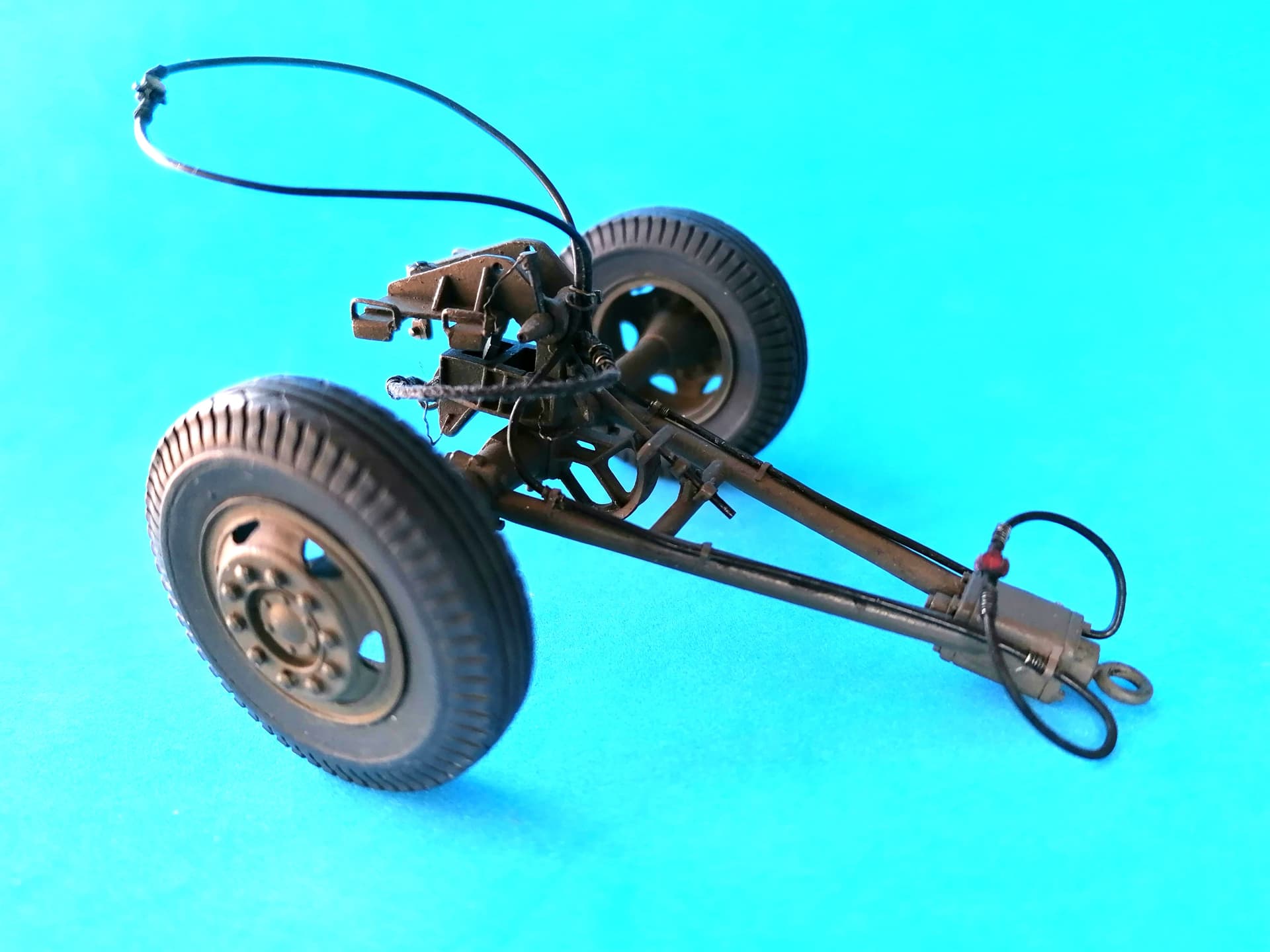
Now the limber is finished, and it will even be “working” once the gun is built.
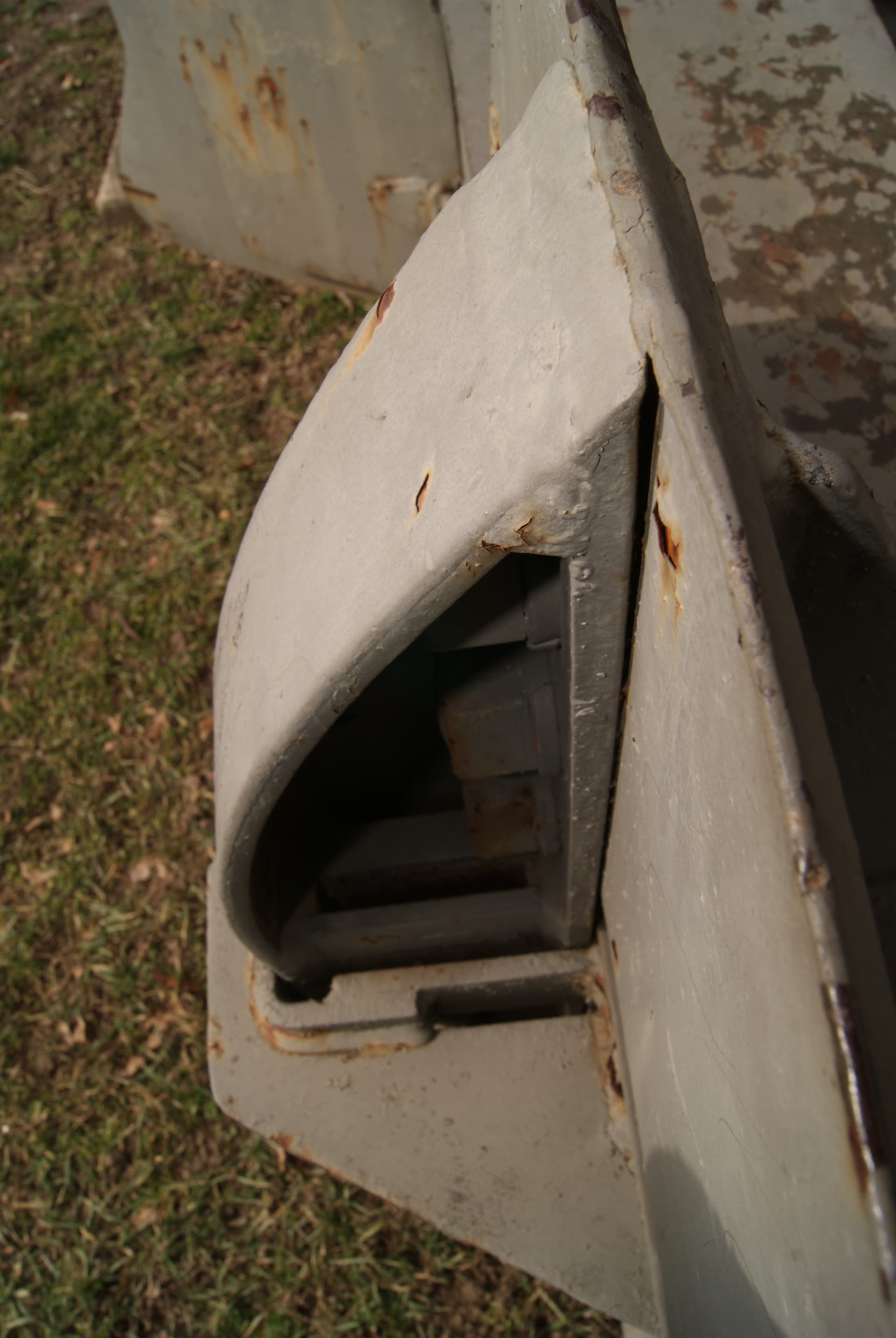
But here’s the next question: I’m wondering about the function of devices on the front spades, namely a vertical slit in one brace and a weld bead on the other. They are mirrored on the two, with the slitted brace at the spade end that allows a look at the bolts that it’s fastened with. The spades are stowed differently on the three guns that I found pictured (at primeportal and Toadman’s) - slits at the front or at the rear.
So, which is correct, and am I right in assuming that these things help extract the spades from the ground when the carriage is lifted? The special shape of the upper front bracket on the trails could be caused by the weld bead’s need for more room, while the slit could allow a wedge to be inserted. When deployed, bead and wedge might arrest the spade in its braces on the carriage when that is lifted.
I can only hope that someone has understood that description and can confirm my guess. Thanks for reading!
2 Likes
A picture would help.
KL
You’re right, Kurt - so here goes; clippings from primeportal, David Lueck’s walkaround
The way I think these things work, they seem to have been exchanged on this gun, because the upper front brace would let the “weld bead” pass, while its open front isn’t necessary to accomodate the “slitted” brace .
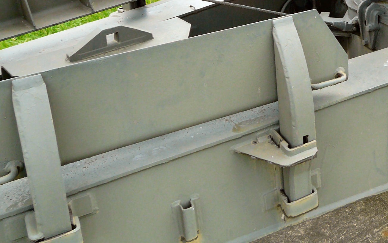
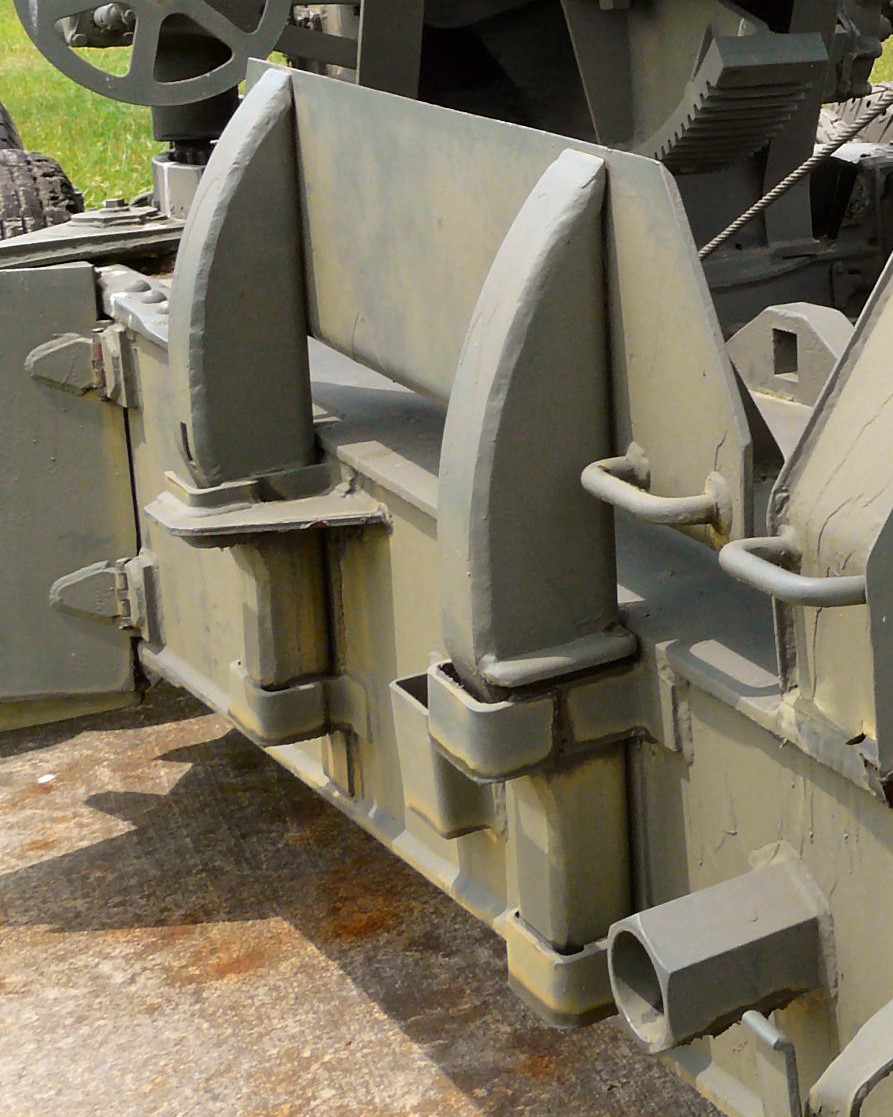
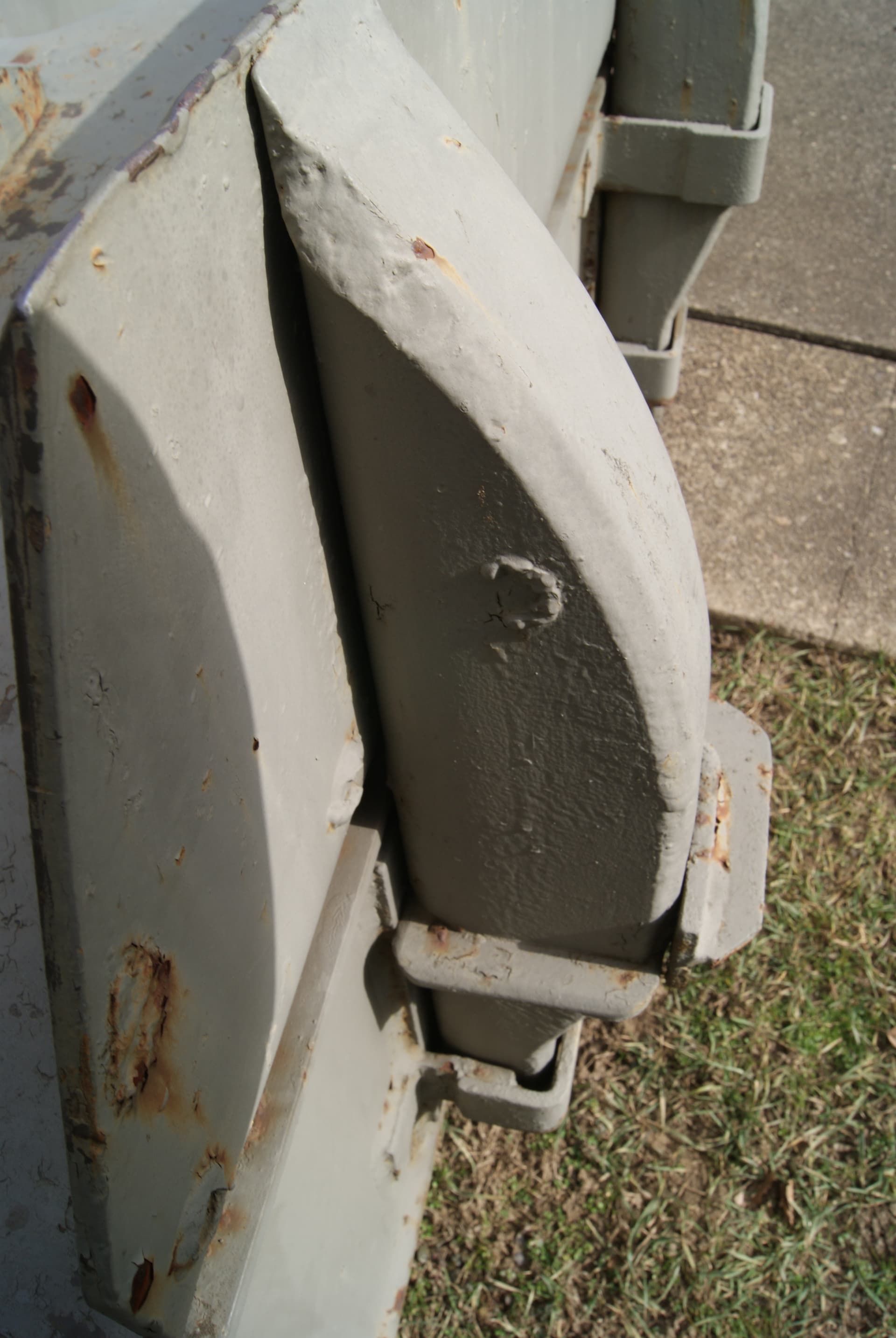
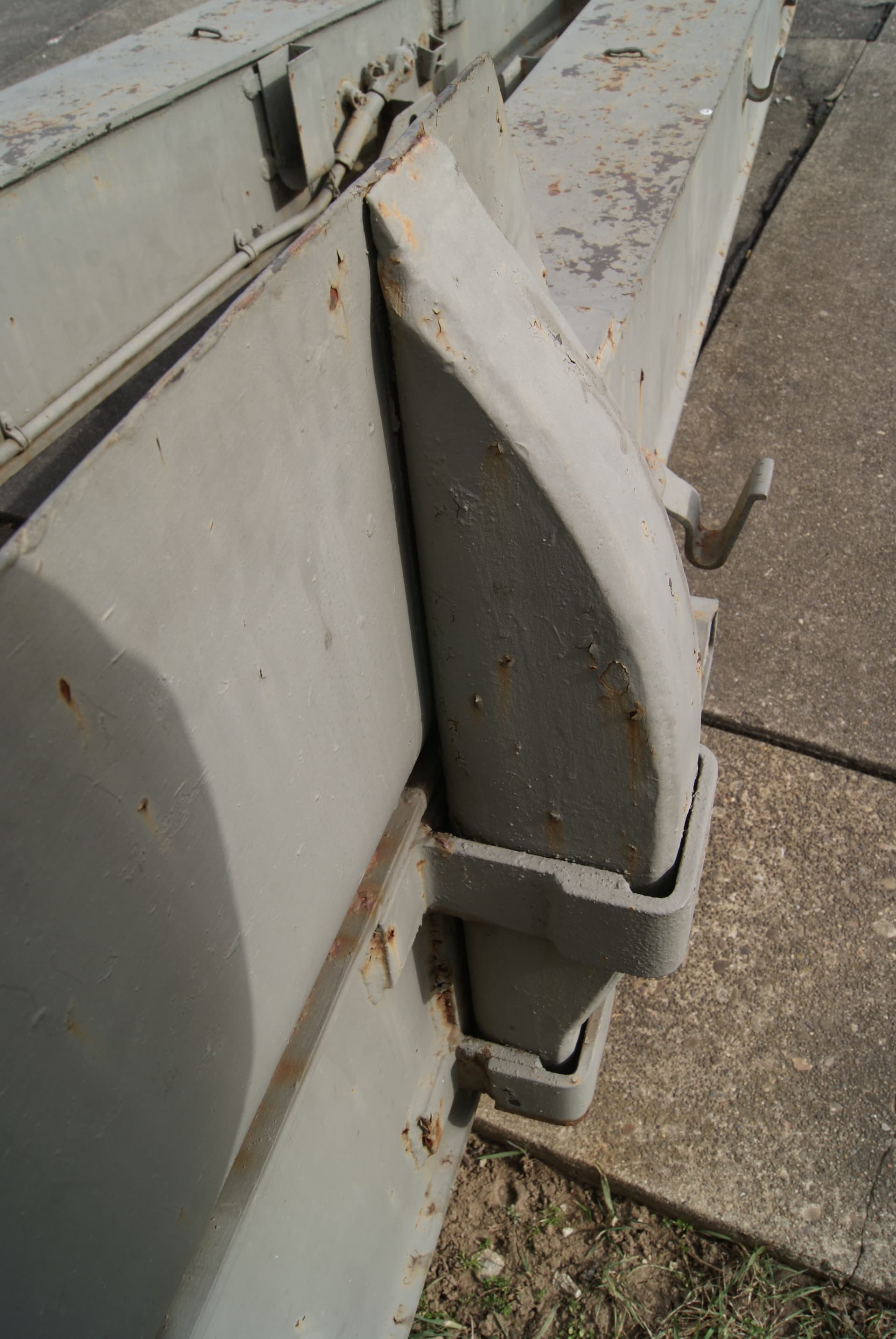
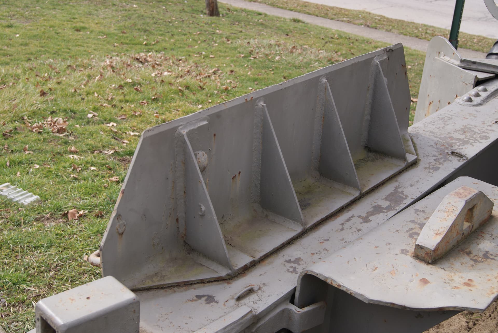
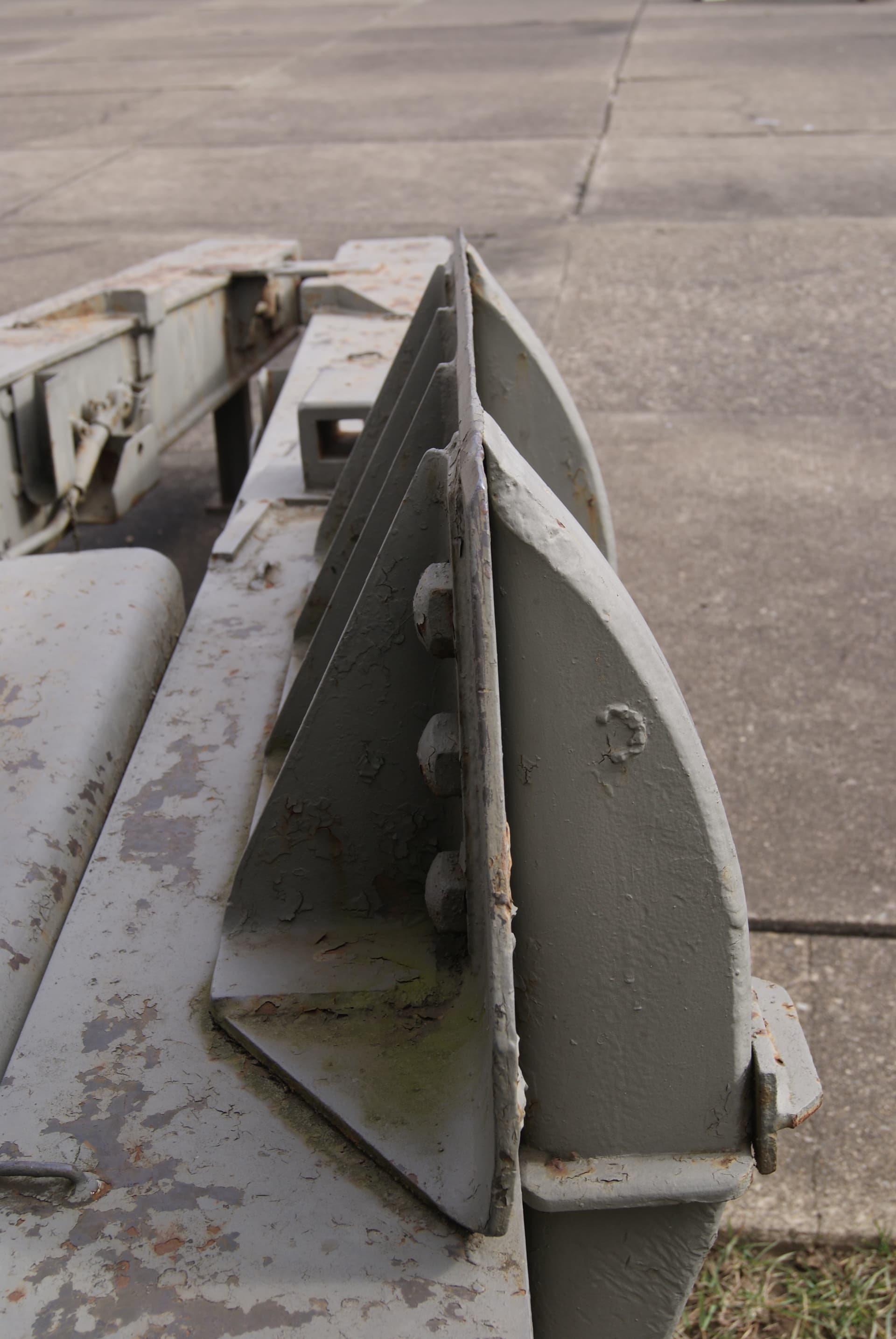
I went down over the hill and took some photos of an M2 8-inch in the local park. That protrusion on the support leg is not a weld bead but a steel bar welded to the support.
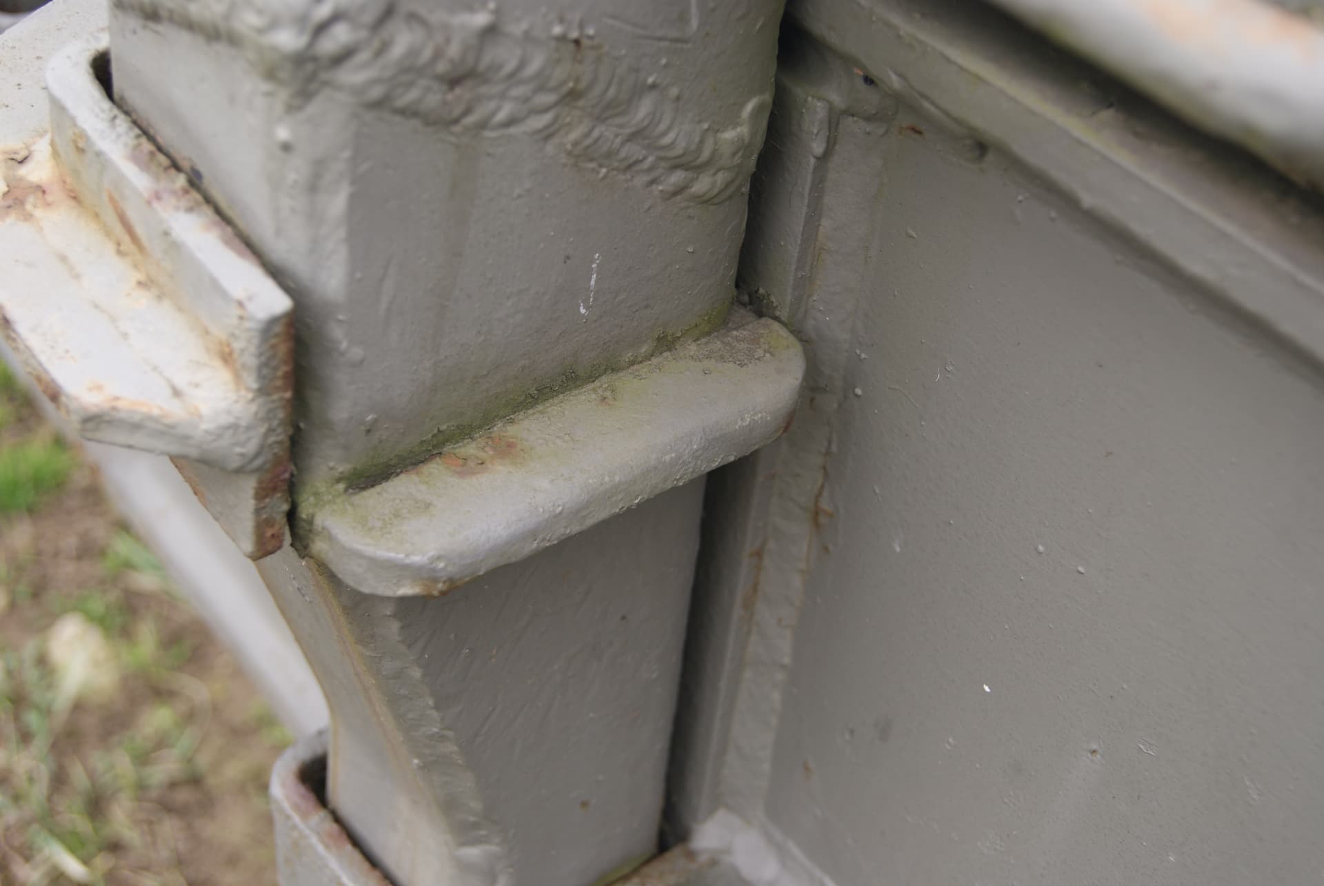
You’ll notice that one of the upper holders is a closed bracket while the other is an open C-shape.
If you’ve ever dealt with something like that (two parallel pins in two parallel holes) you know how difficult it can be to fit together because the any spacing variation or parallelism variation makes the pins not match the holes. Often times one of the holes is slotted to account for this, or in this case, the slot breaks through the end.
My guess is that the bar is to insure that the spade is placed in the holders properly, with the spade plate over the trails. The bar won’t fit into the closed holder. It also prevents a left-right mix-up. The slot in the other support is likely to allow lifting the spade with a pry bar if it sticks when manually pulling on the handles fails.
KL
4 Likes
From a 1943 TM:
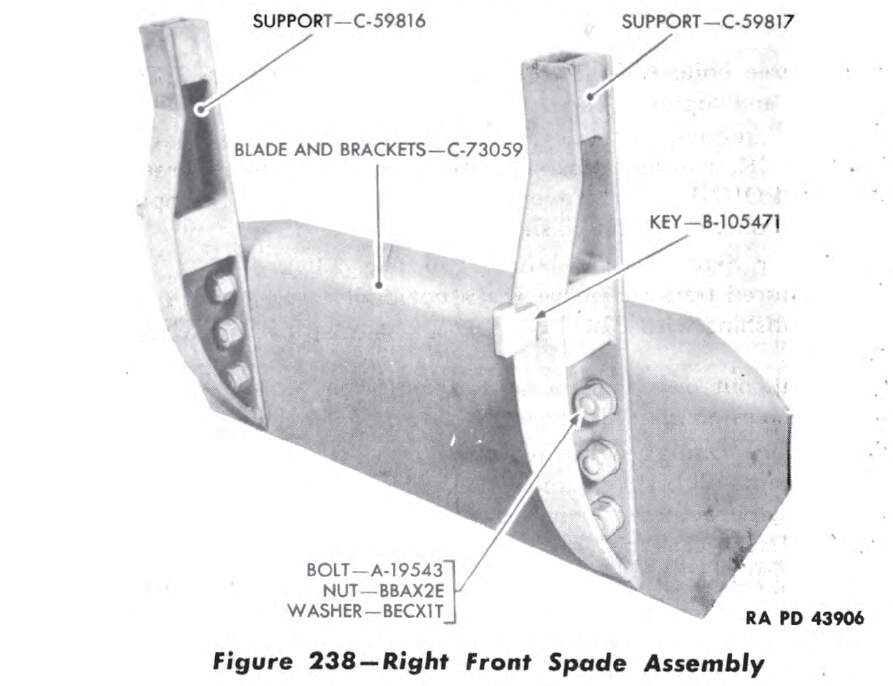
The KEY does not seem to be present on any survivors. The Field Manual says (but doesn’t illustrate) that the spades are held in place with a key. This block might fit a slot or space in the spade brackets on the lower carriage.
KL
3 Likes
Thank you very much, Kurt! Your pics prove my suspicion that on the gun in my photos, the spades are stowed wrongly: the right one on the left trail, and vice versa.
As for the keys, my conjecture is that with the spades mounted under the carriage, the protruding end of the key and the steel bar would rest on top of their respective braces, thus pulling out the spades when the carriage is raised. I also remember having read somewhere in a TM that these keys doubled to lock the closed trail doors by being inserted in the “U” going through the slot on the carriage (but can’t find where I read it any more, of course).
Anyway, until further findings that’s how I’m going to treat my spades - thanks once again for helping out.
1 Like
The key in the TM illustration is welded to the support, so it can’t lock anything. The trail doors were held closed by a small clip on a chain that went through a hole in a tab on the door that itself went through a slot on the lower carriage.
KL
2 Likes
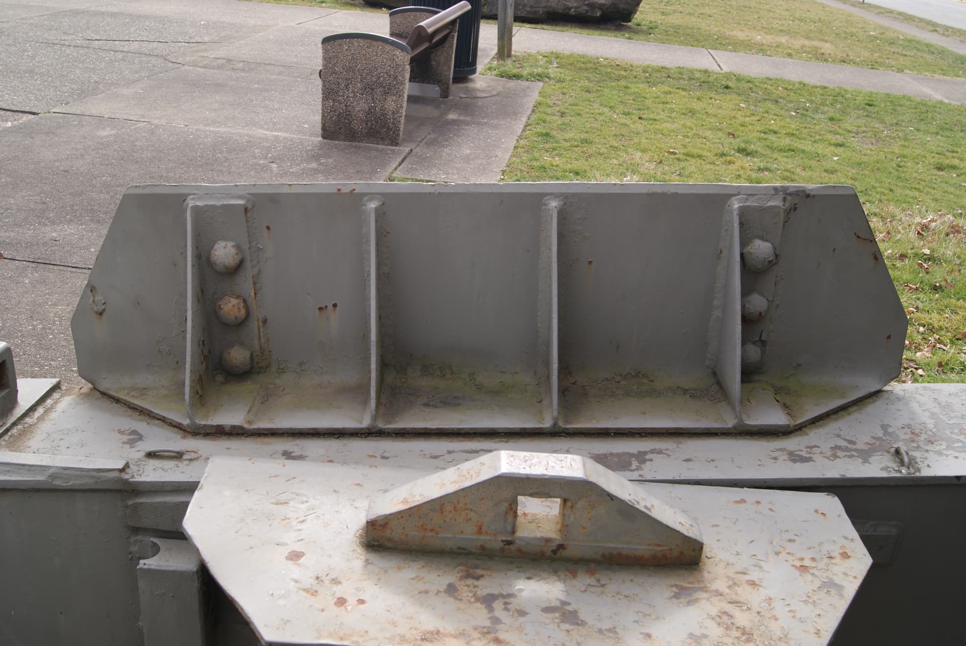
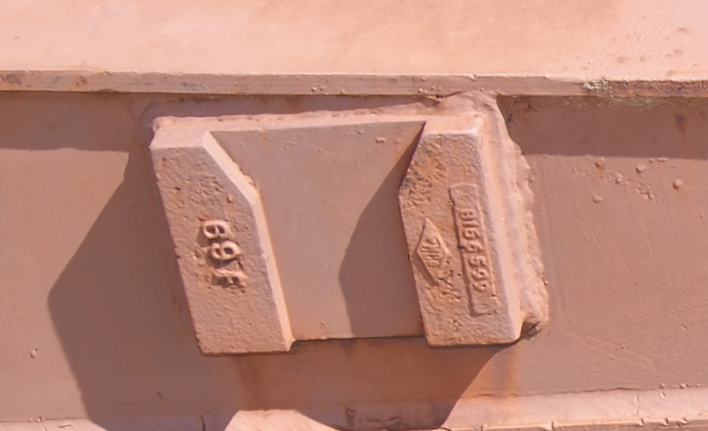
It is well known that AFV Club’s first attempt at the Long Tom (AF3509) was less than perfect, and the same went for Eduard’s PE set 35 295. But even on the much better “WW II version” (AF 35295) there are moldings on the trails that resemble (!) what David Doyle identifies as “bracket into which the detachable spare-tire holder slid” on p.12 of his “Long Tom In Action” book:
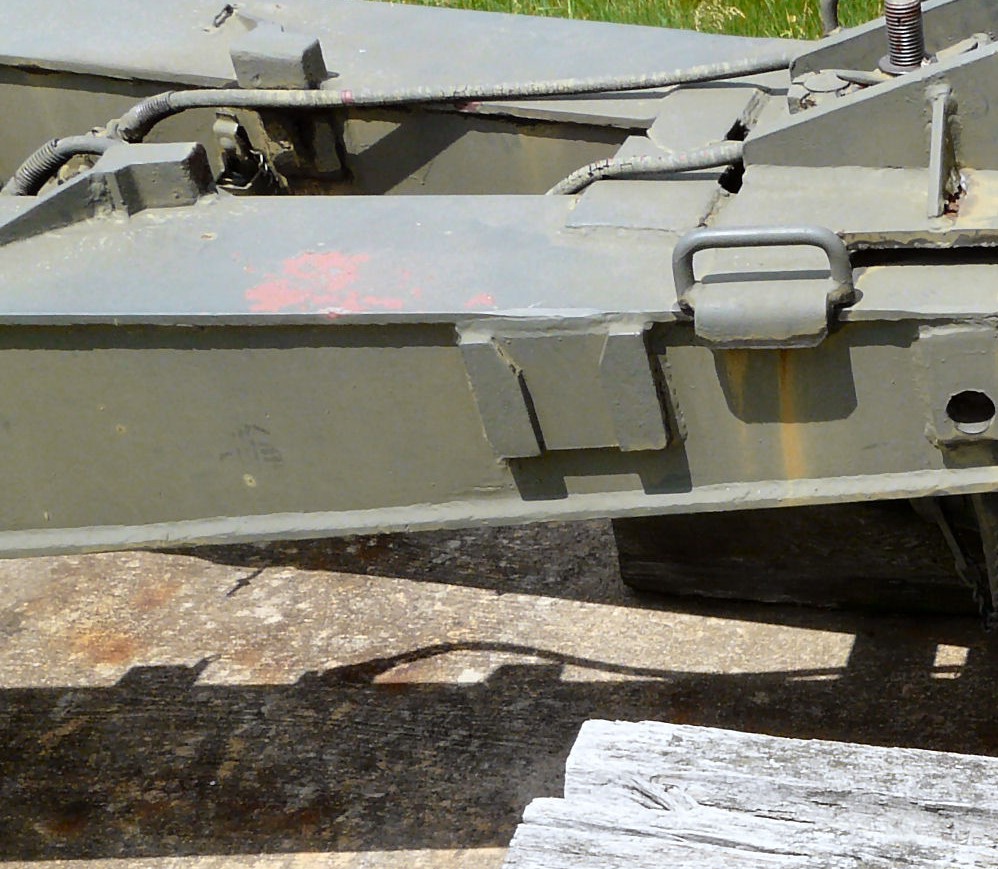
That thing in the center of David Lueck’s photo at primeportal is rendered in the Eduard set as a “hollow” folded part, whereas in this and other photos, at least the tops of the sides appear massive. Hence my question: What is the purpose of these contraptions, and might that explain their shape?
AMS is a terrible disease …
Peter
Those weren’t for tire carriers. I have only seen tire carriers on very early carriages and they were farther toward the weapon. If they were placed at this location the spares would interfere with the limber wheels.
They are officially “guides”, and are used to locate guide bars on the M2 limber.
The guides themselves are castings.
KL
1 Like