Aaaaah, thanks a lot, Kurt! So there’s another mistake in the Ed set, and the kit’s moldings (that I have removed already) are right. Sigh.
I never remove the plastic until I build and check the PE.
I have found that, at best, about a third of the PE in the larger Eduard, Voyager, Aber, etc. sets is usable and as time has gone on the number has gone down. There is always some portion that is the wrong/different version, more that look worse than the kit part, and many (like here) where the etch company would have you replace a 1-inch thick casting with what works out to be <3/16 thick sheet metal.
Besides the fact that it is obvious that many of the pieces just copy the kit shapes without knowing what they are or how they are constructed, the basic problem is that tanks are not solely built from 0.175 inch thick sheet metal or laminations of the same. Plate, castings, forgings, tubing, rod, and bars are also used and look different even in 1/35 or 1/48 scale. Just making some parts out of 0.007 or 0.010 metal would be a significant improvement.
We would be better served if the etch companies would stick to making parts that really are sheet metal and including some corrections rather than mere kit copies.
KL
4 Likes
Life sucks sometimes …
100% agree!
Ken
3 Likes
Same here.
1 Like
I’ve replaced the “guides” for the M2 limber with sheet styrene and “welded” them in place:
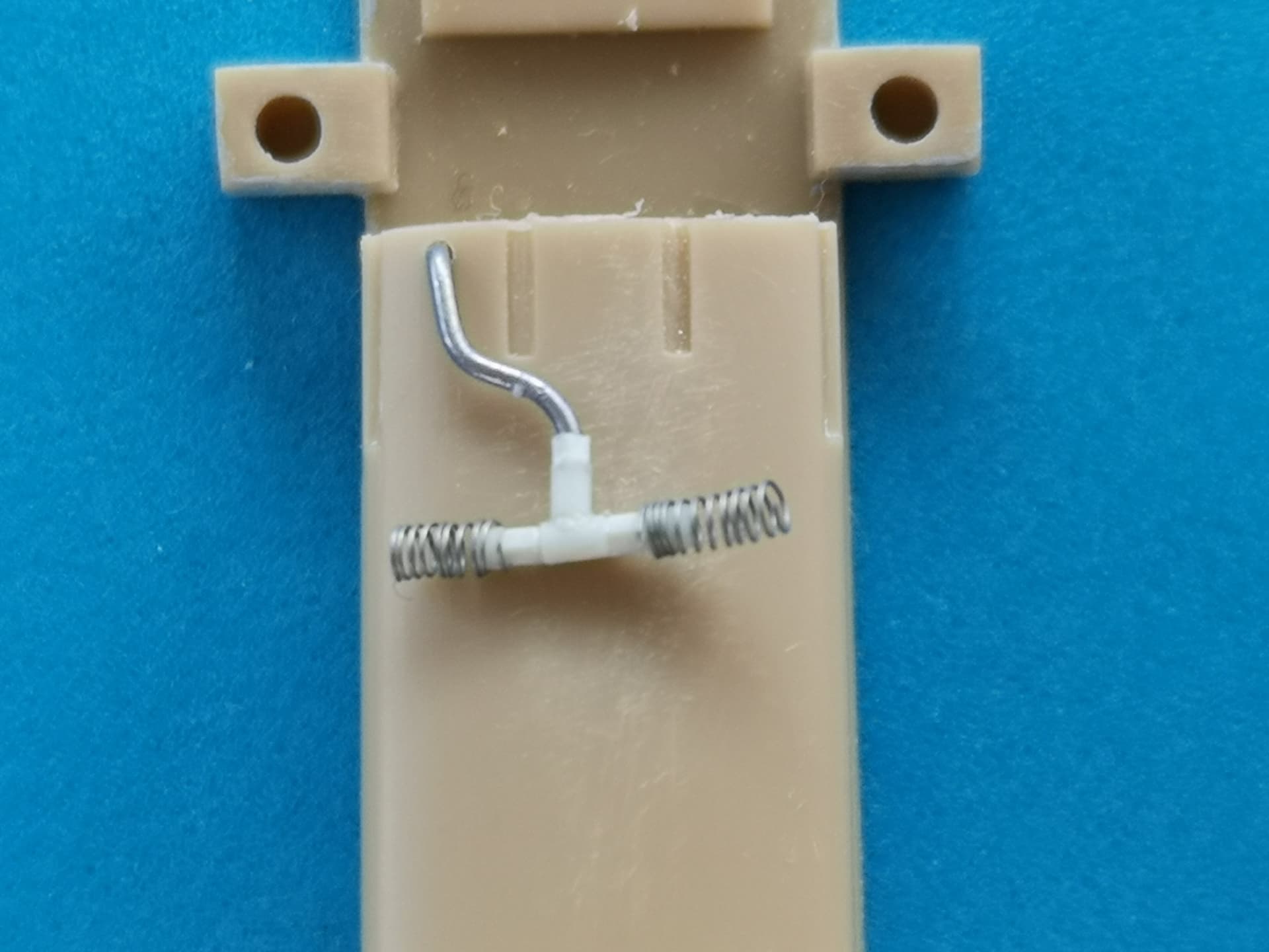
Regarding PE sets that offer lots of nonsensical “PE for PE’s sake”, Eduard’s #35295 for the M59 is a case in point: PE replacements for the massive recoil spade brackets , trail doors w/o the upper triangles, lock and hinges for the periscope case to be installed on the wrong side - in short, it was a really good decision to “discontinue” this set. Of its very few usable parts, the “toothed racks” for the brake handles really helped and also prompted me to replace the operating rod with stretched sprue,while I found the set’s operating lever parts insufficient.

Now here comes my next question: Where exactly does the brake line come from that feeds the lines that branch off the “T” towards the wheels, the one going to the upper right in the pic?

Thank you everybody for watching,
Peter
2 Likes
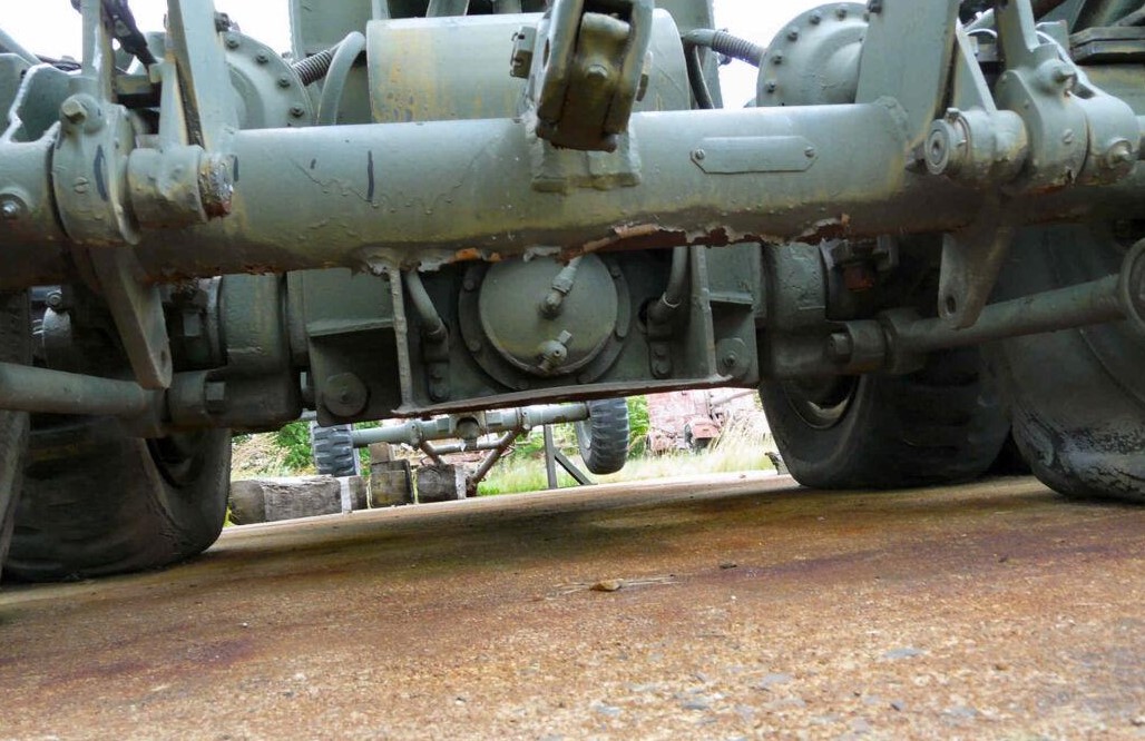
I doubt that, Henri Pierre: The air is delivered from the towing vehicle, via limber and trails, to the carriage. There, the line is divided into one for the front and one for the rear wheels (as seen in the direction of travel). The air tank your picture shows seems to feed the rear wheels, while the line I asked about is closer to the source of air, so … And anyway, for my model I don’t really care where the air in that line feeding the “T” comes from but just where this line comes out of the carriage, i.e. where I have to drill a hole.
Thanks anyway!
1 Like
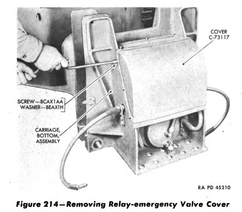
Perhaps this will help:


Looks like the emergency relay valve.
Normally that’s all hidden
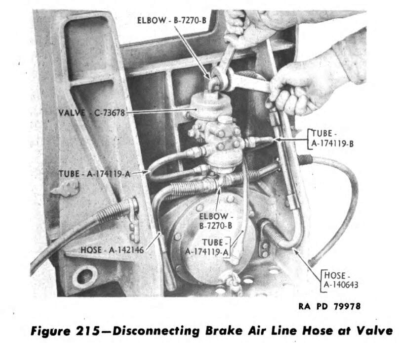
I’m thinking you are seeing the other end of TUBE A-174119-B.
KL
5 Likes
Bingo! That’s exactly what I needed, while at the same time it shows that Frenchy’s guess was right. Thank you both once again,
Peter
2 Likes
Well, no. The line from the tank connects to the relay valve while the brake lines connect to the sides of the emergency valve.
KL
1 Like
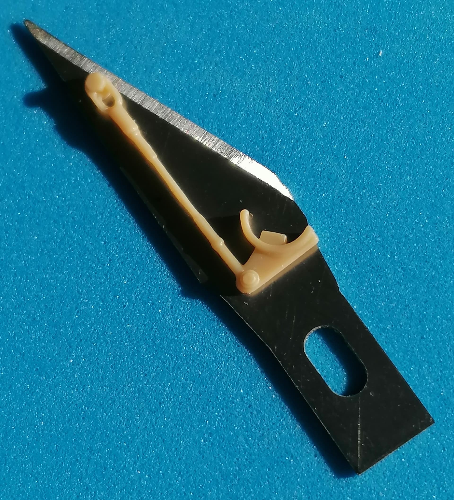
Here’s what I’ve cobbled up, so far just placed on the carriage.
Next problem are the “wheel supporting cables” (kit parts B34,35) that are rigid, but so fine that replacing them with operable (or at least placeable) parts will be more than difficult: The “cable” is the central part of the contraption, with a length of 5mm and an estimated diameter of 0.25mm. And the eye would have to be drilled out, while there would have to be a “fork” at the other end …
I have a dim memory that someone (here, or on armorama?) had problems with his model because these things lifted one of the carriage axles, but I can’t remember what he was advised. Anyone have a better memory or an idea how to make these things hang on brackets on the upper torque rods?
3 Likes
Judging by the number of replies to the preceding post, I guess I’m the only madman who cares about this detail of the Long Tom kit, so here’s what solution I’ve come up with:
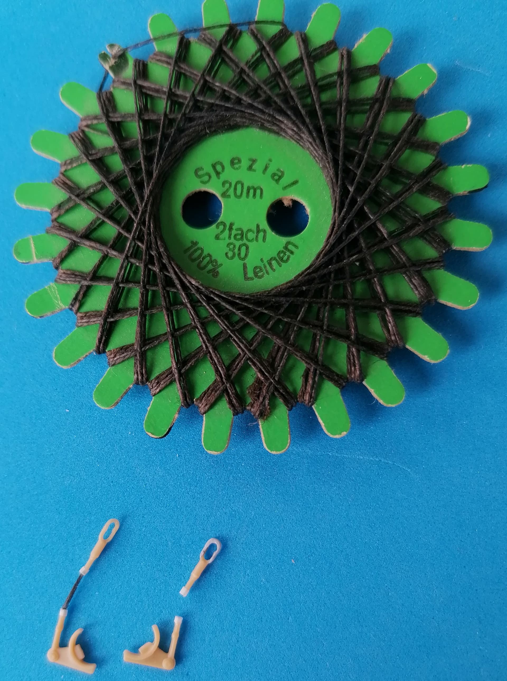
The kit parts were cut apart and their “cable” representations discarded. The eyes were freed from outer details and drilled out. “Nuts” of 0.5mm Plastruct hexagon rod were then added to both fixtures and strong linen thread “cables” glued into depressions drilled into the nuts. New Torque Bracket Bolts will be added to the bogie crossbeam B42 and hooks around the upper torque rods as soon as my right thumb will have healed from a fracture - in five or so weeks.
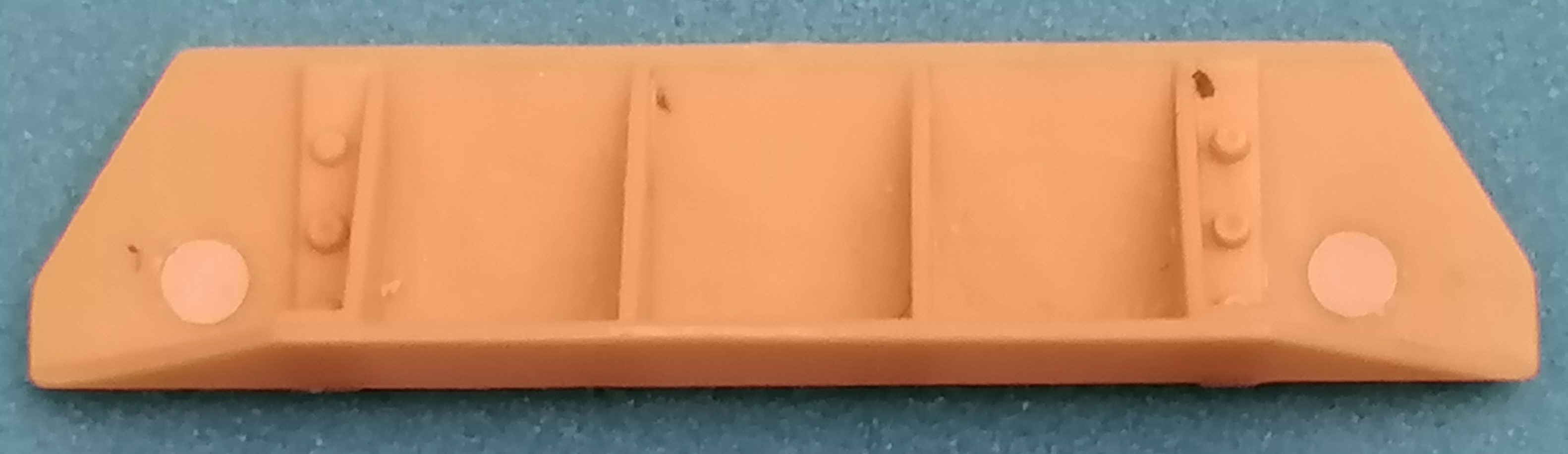
And while healing up, I discovered the next problem. Anyone who bought Eduard’s set #35 295 for the Long Tom will have understood why it was “discontinued”: Replacing massive steel brackets for the spades with sheet metal is nonsense, the offered replacement hinges for the periscope case are supposed to be mounted in simply wrong places, the trail “doors” are misssing the triangles on their tops, and the list goes on. The only parts I eventually decided to use were the spade key brackets on the trail outsides and the ramming/cleaning rod stowages on the insides. But then, when I was just shaking my head at the strange parts 19 and 38 and considering to ignore them,
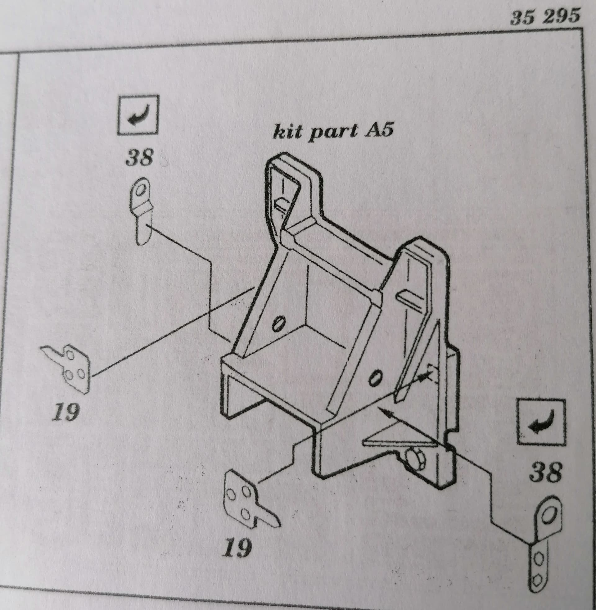
I found on p. 28 of TM 9-3038 that these parts are “Alinement and Pointer Plates”, indicating whether debris has lodged under the bearing surfaces of the lifting screws.

Once you start looking for them, pointer plates 19 can easily be seen in Kurt’s above figures from the TM and Toadman’s pictures. Fine - but the purpose of indicator plates 38 demands them to be mounted on the bogie crossbeam, not as Ed wants them. JUST HOW AND WHERE??
As I said, I won’t be able to use that info during the next weeks - amazing how much of a handicap that li’l bone underneath your thumbnail can turn out to be!
1 Like
Eduard Item 38 is a brace (air line hose support bracket . . .) for the air lines coming through the holes in kit part A5. The eyes should line up with the holes in A5.
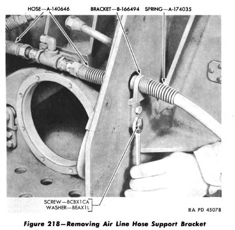
They look to be a bit thicker than the scale 0.175 inches that PE gives you, like double the thickness.
BTW, it looks like most of the hoses have some sort of brace keeping the hoses aligned with their fitting so the don’t kink or damage the threaded connections.

KL
1 Like
Thank you very much, Kurt!
With this information, even Ed’s drawing almost makes sense - if only the kit part had come with the appropriate holes …
Peter
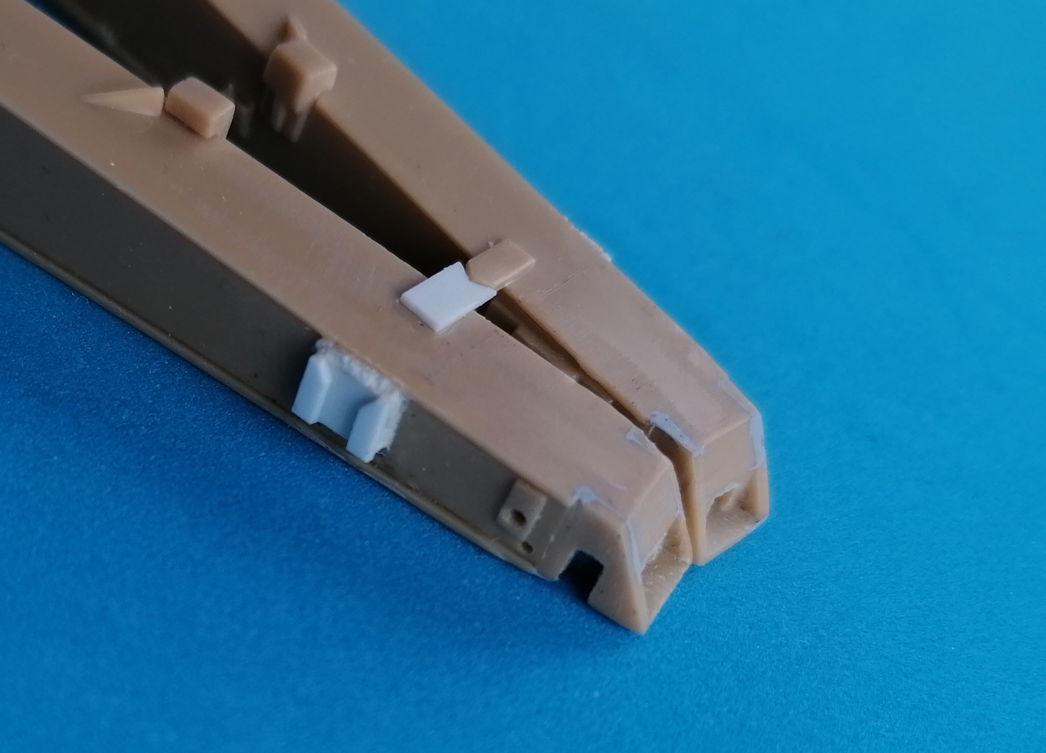
At long last, my thumb’s healing allows some modeling again. And the next problem came up.
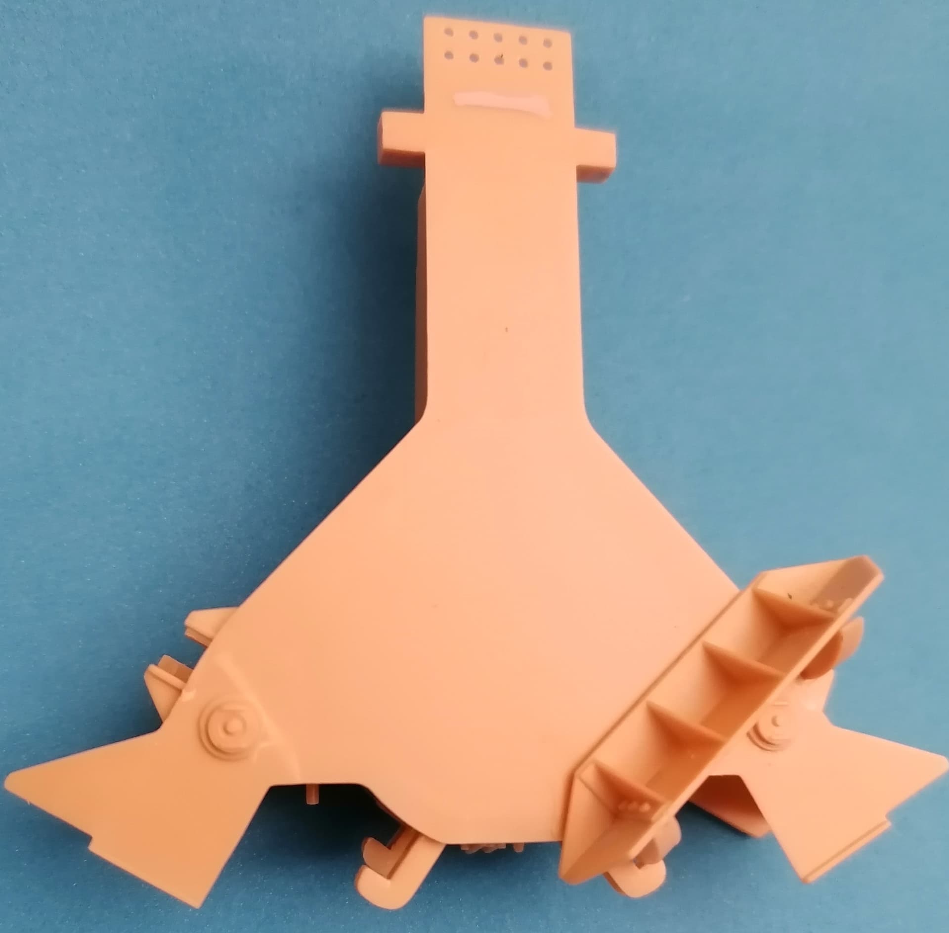
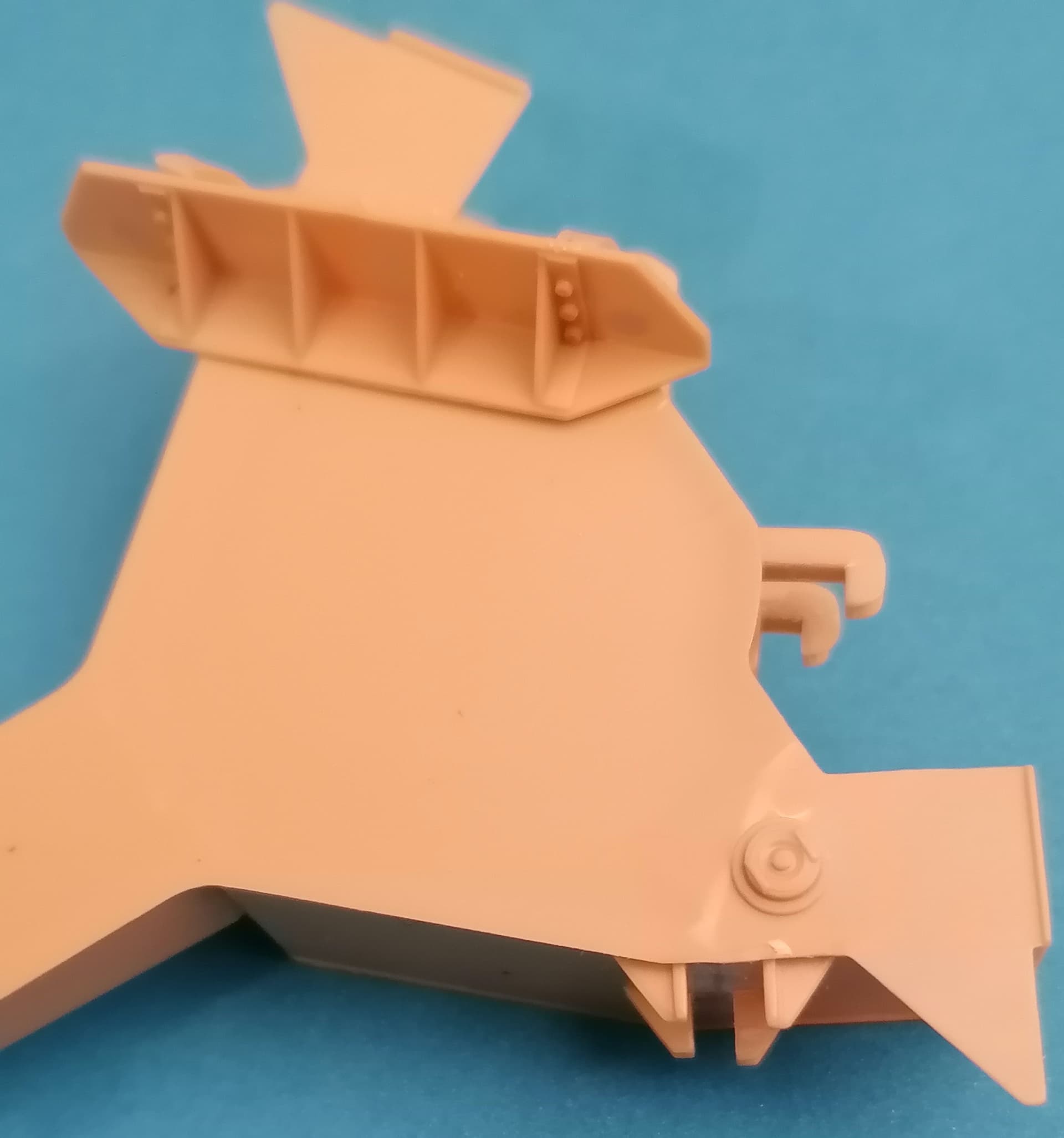
The front spades received their braces so they would sit correctly on the trails:
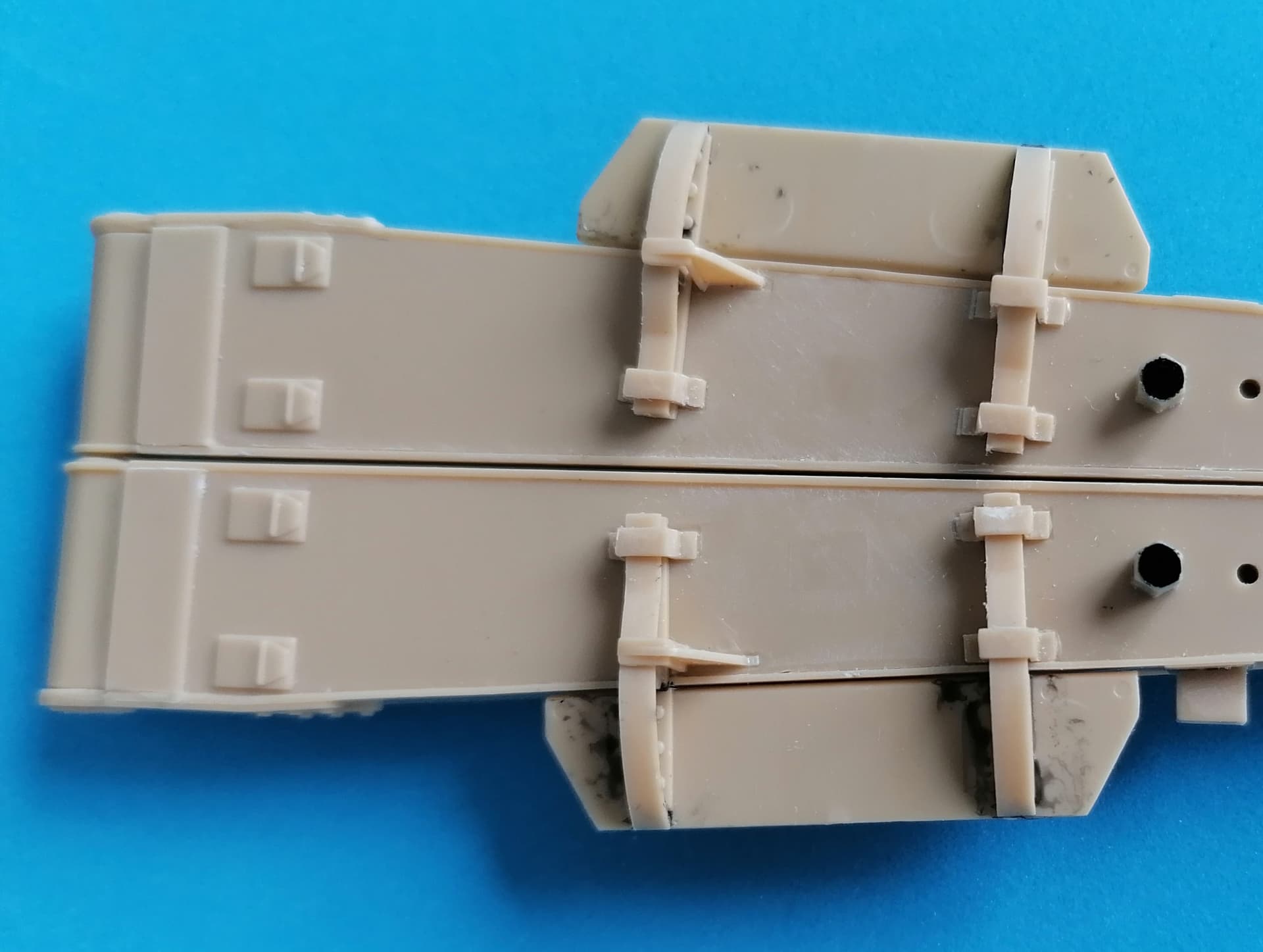
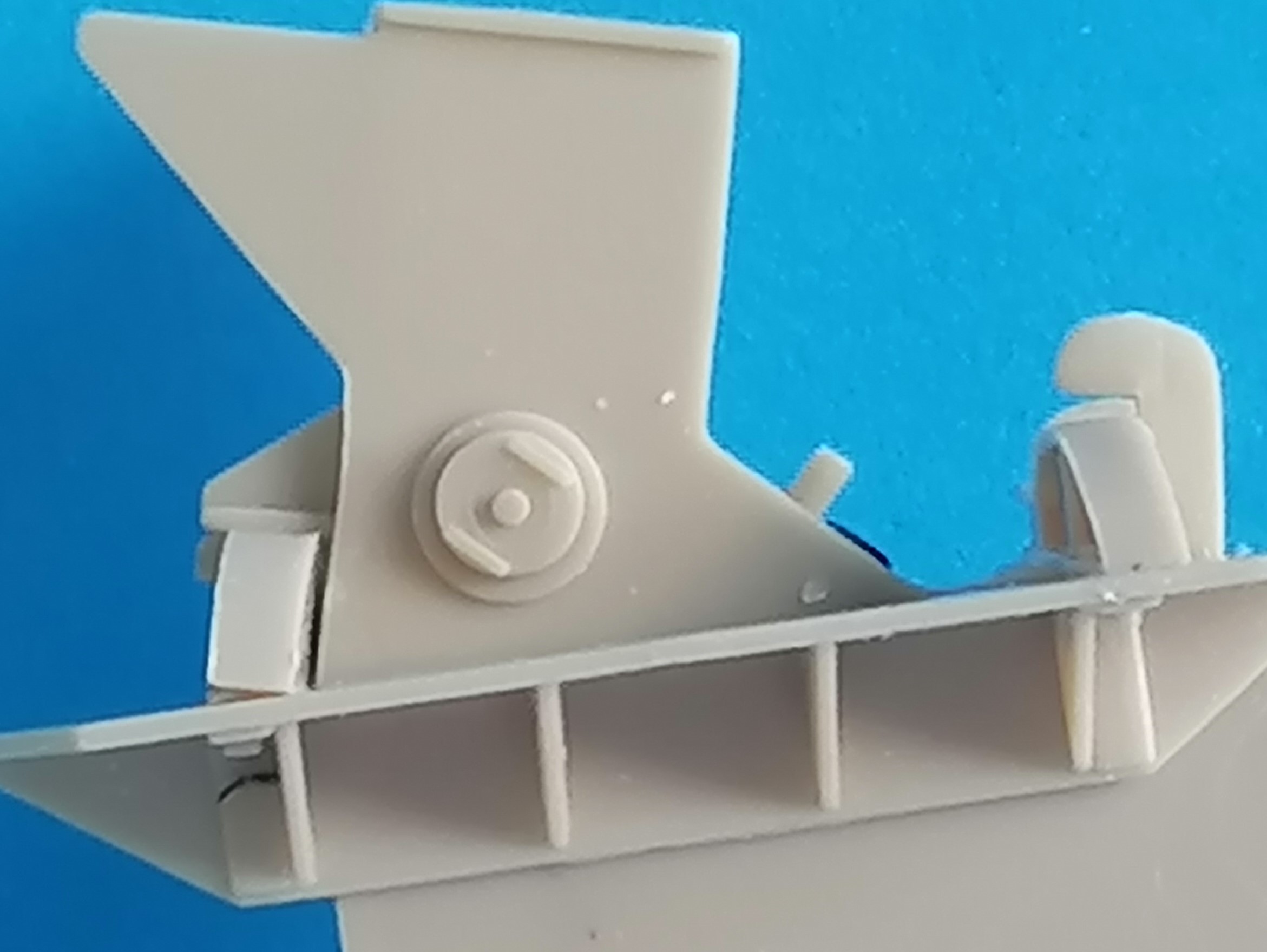
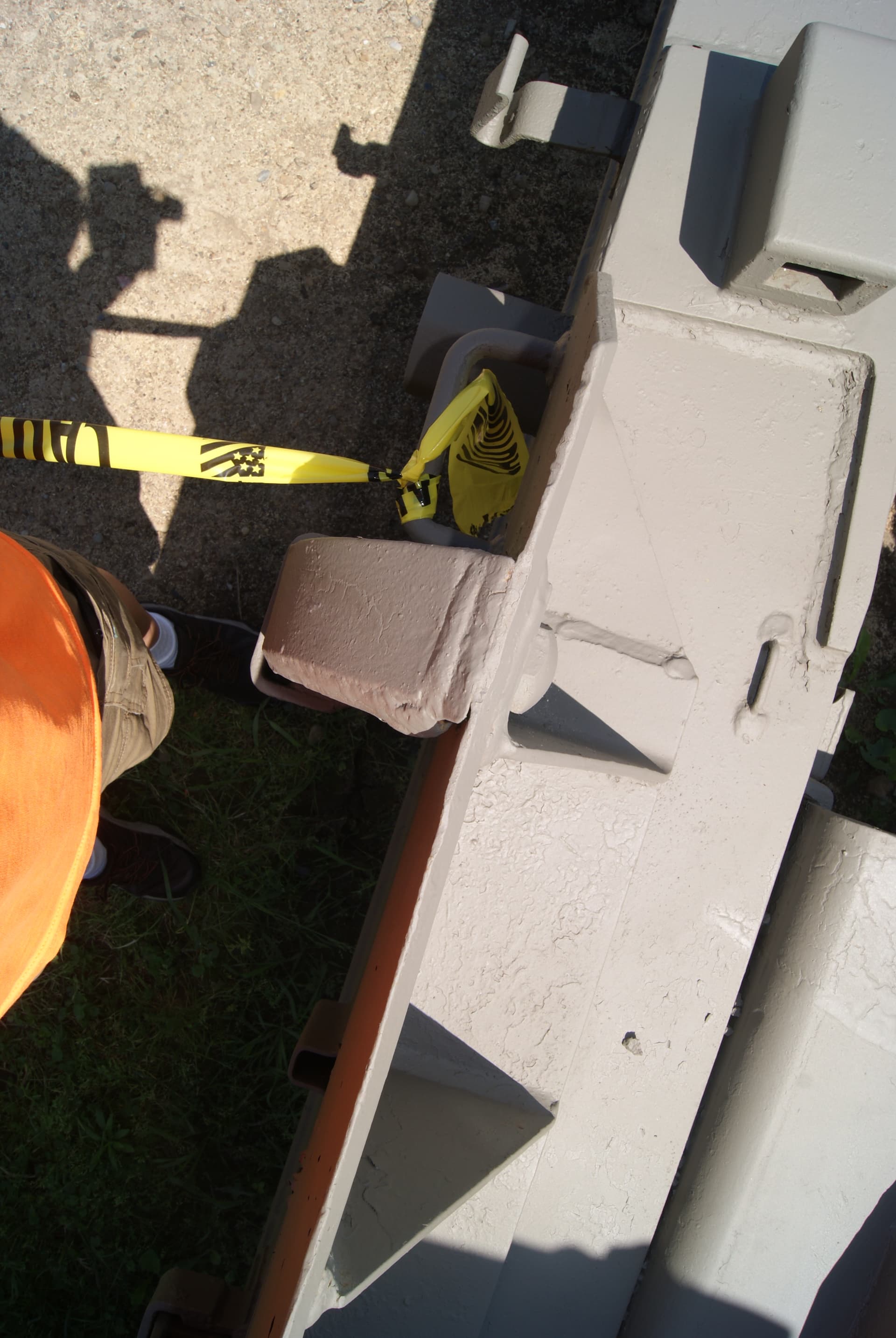
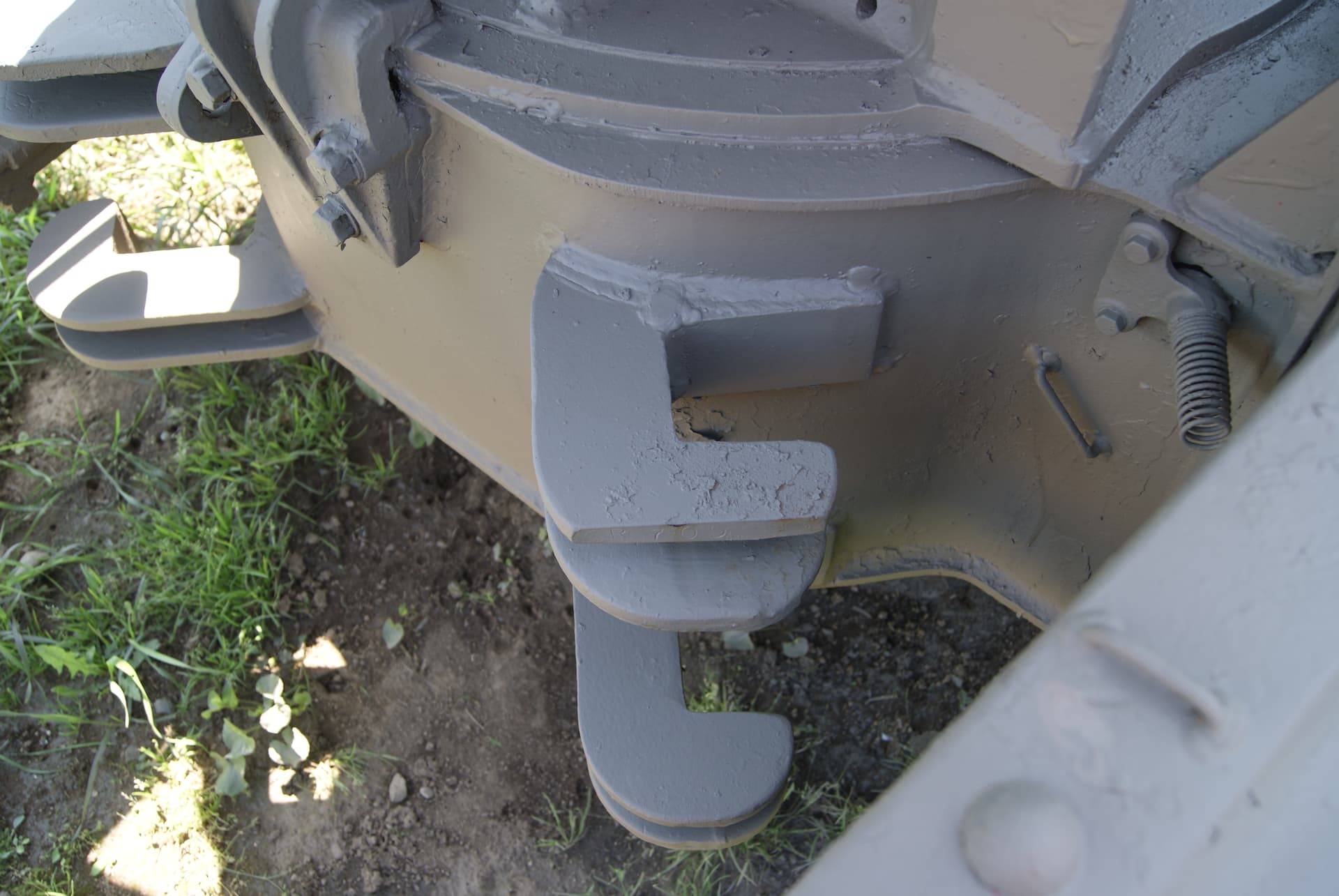
Fortunately, I did that with white glue only (tinted black with gouache), because it turned out that the guides on the carriage outsides demand the braces there to be installed at an angle I couldn’t find in any pictures of the prototype, so there’s got to be a mistake somewhere. The question being whether it’s mine or AFV Club’s? (Photo showing carriage bottom, left side in direction of fire.)
Any explanation would be greatly appreciated.
1 Like
The arms of the spades should not be tilted, in either direction.
I would adjust the kit’s brackets such that the inner ones are symmetrical and the outers fit.
KL
2 Likes
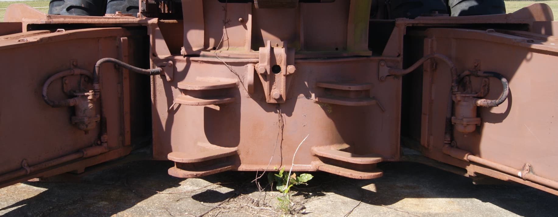
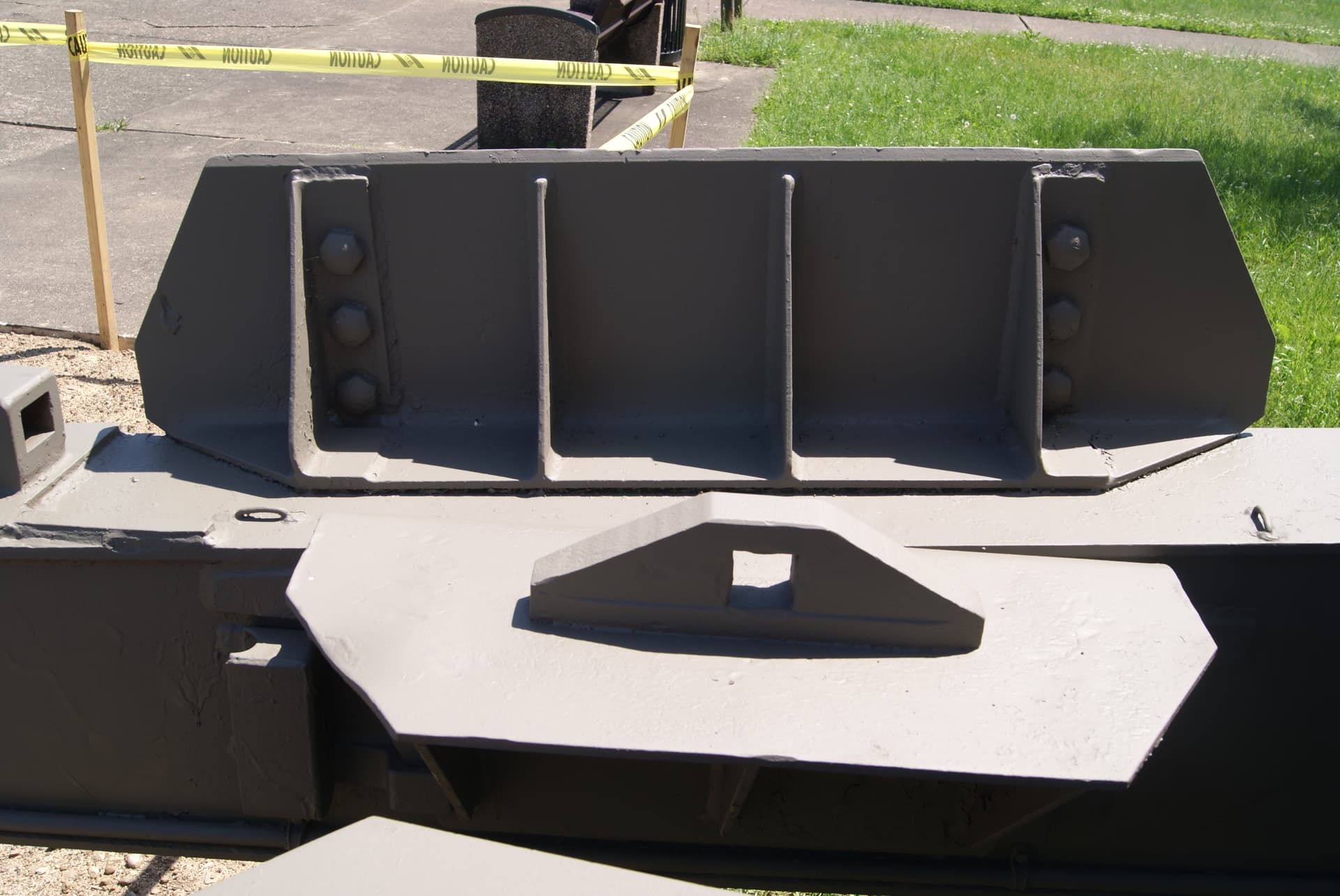
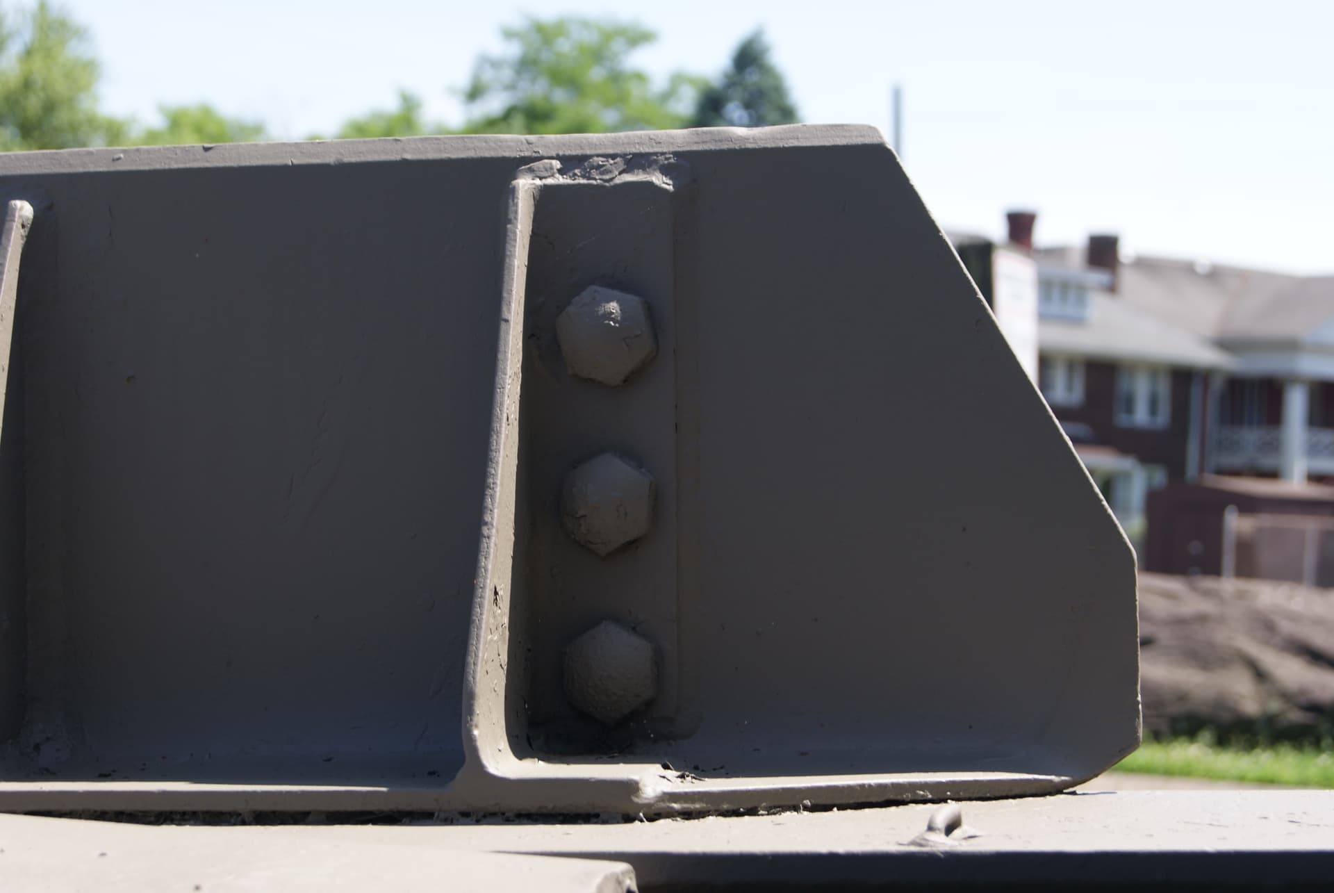
I think your spade legs might be spaced too far apart. Note on the spade in the background in my upper photo that the mounting bolts are to the outside of the gusset on the right but inside of the gusset on the left. It looks like yours are both to the outside.
KL
1 Like
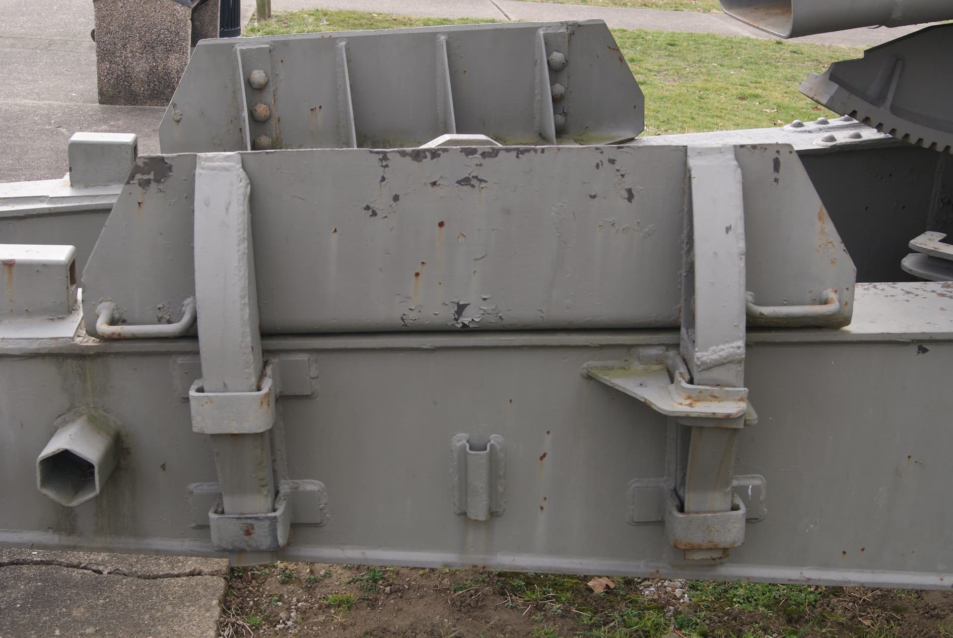
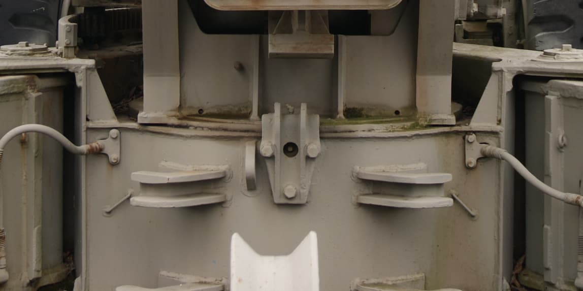
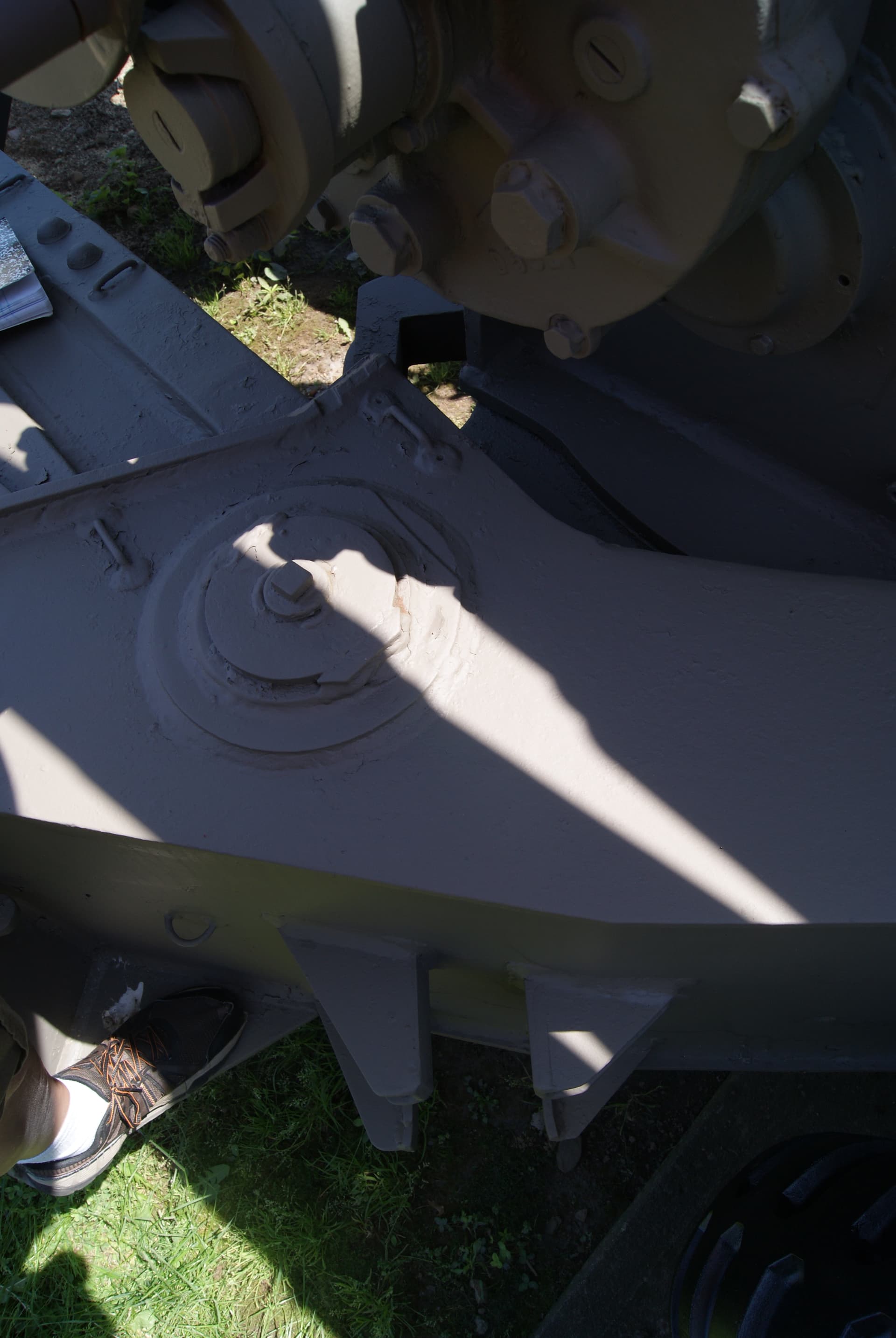
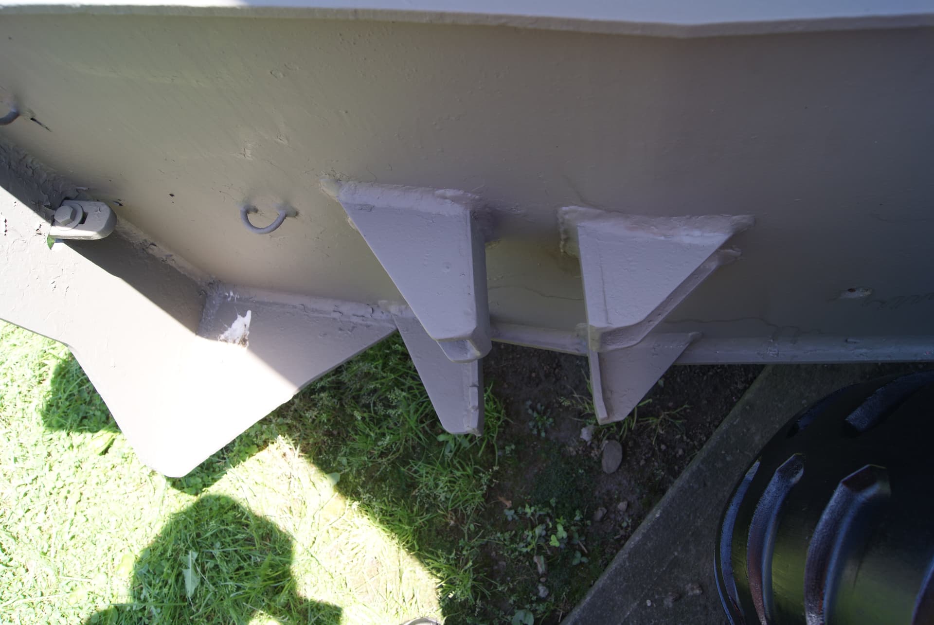
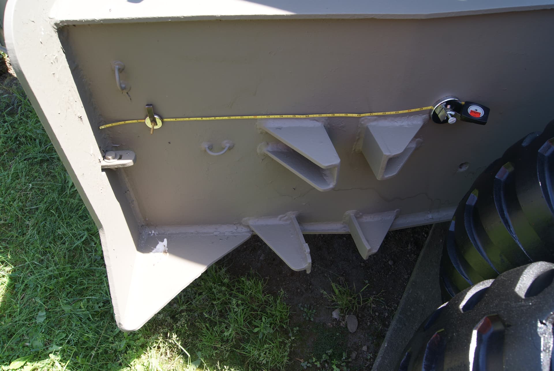
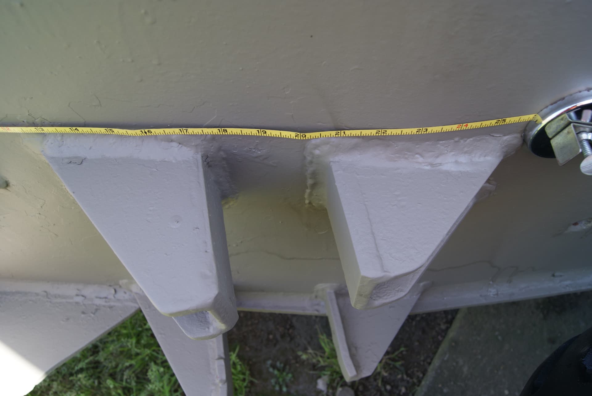
I went out to a local 8-inch howitzer and took some photos and measurements for you.
KL
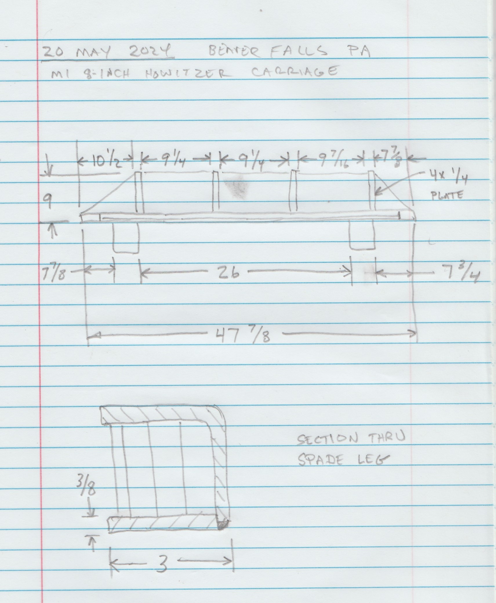
The measurements do not add up, which is typical with welded assemblies. Overall numbers are usually more accurate than a sum of smaller dimensions. I would just use common fractions and make reasonable judgements.
KL
3 Likes
Thank you muchisimo for the work you did, Kurt - you found the reason for the misalignment!
The kit’s spade legs aren’t too far apart, otherwise they wouldn’t fit into the stowage brackets on the trails; but the “left” gussets on the insides of the spades have been misplaced by AFV (which however doesn’t affect the position of the spades on either trails or carriage).
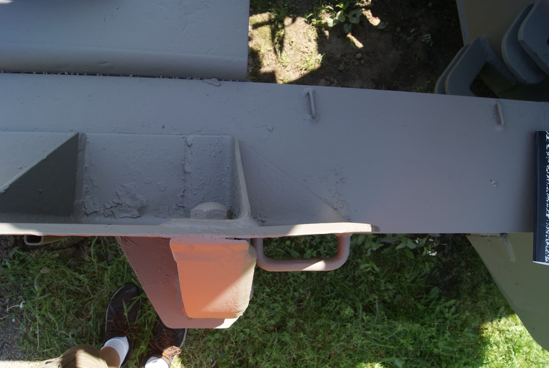
The real problem is answered by your last four pictures: The spade leg guides/brackets on the outside of the carriage open at right angles to the carriage body in the kit, while in reality, their opening is slanted forward, thus achieving the correct angle for the guidance of the outside spade legs.
I don’t know yet how I’ll correct that. But I’m amazed that in the 30 years of this kit’s existence, apparently nobody ever tried to build it with the spades in place (or sufficiently cared about their misalignment in a kit review or build report).
Thanks a lot again, Kurt - that was another proof of this forum’s greatness!
Peter
2 Likes