My broken thumb prevented model building, but not research: I found two TMs for this gun on the web:
TM 9-350, 7 may 1945, TM 9-350 155-mm Gun M2, Carriage M1 and M1A1, Gun Mount M13, Heavy Carriage Limber M2 and M5, and Firing Platform M1 : United States. War Department : Free Download, Borrow, and Streaming : Internet Archive and
TM 9-3038, september 1955, 155-mm Gun M2: Carriage M1 and Heavy Carriage Limber M5: Operation and Organizational Maintenance (Technical Manual TM 9-3038) - Payhip
Between the two, they provided me with these informations: “Remove keys from two trail doors (fig. 1), and open doors. (These keys will be used to secure front spades to trails.)”, “Swing the trails open and secure the [rear] spades to the trails by means of the trail spade keys (fig. 2).” and “Swing the trails closed, close the trail doors (fig. 1) and fasten with the keys removed from the front spades.”
L-shaped keys for the spades at the trail ends could be made from 1x1mm styrene strip - they’re also used to secure the A-shaped travel brace on the trails and can be stowed on the outside of the left trail.
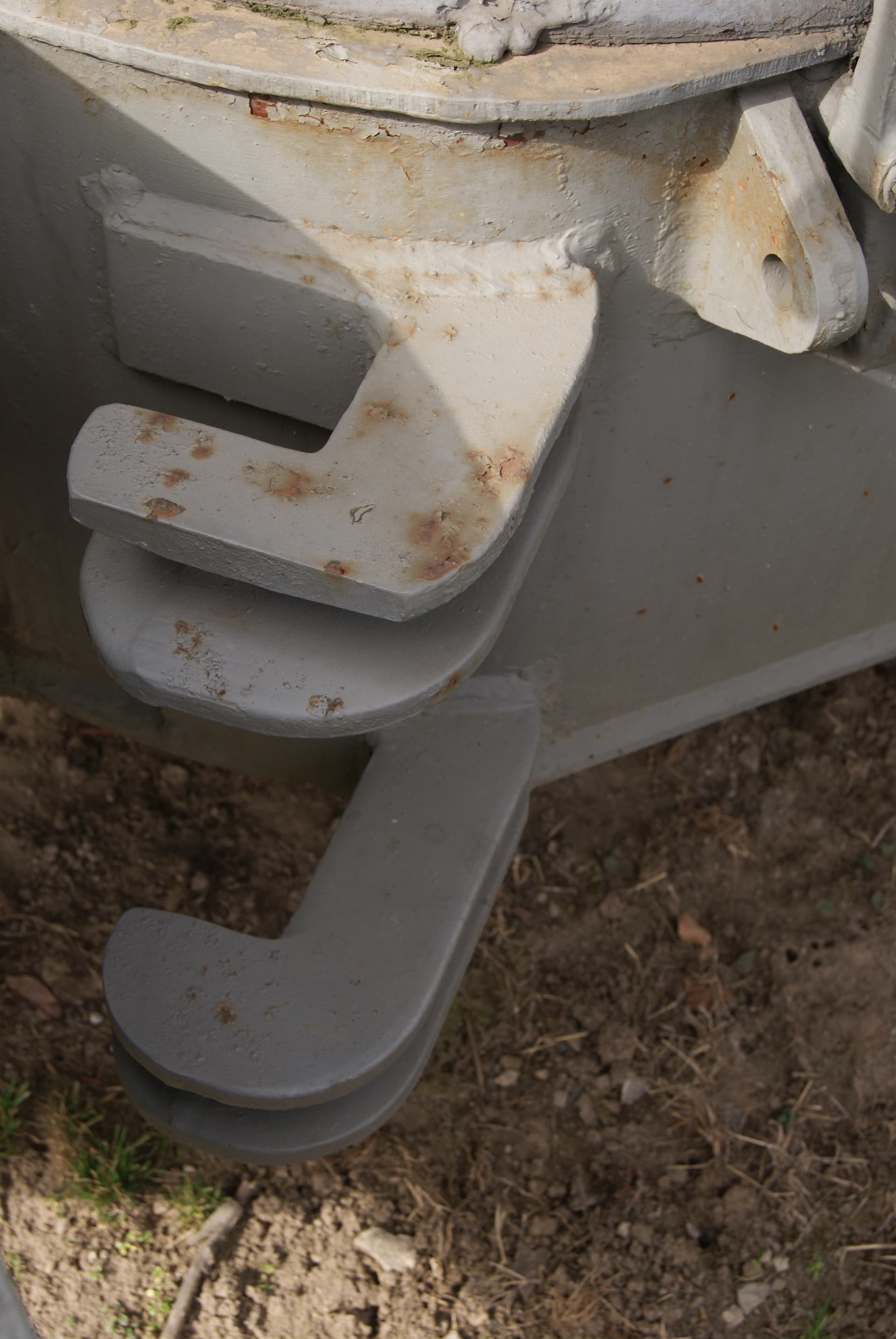
Searching walkarounds showed front spade keys in place on the trail doors, e.g. at Toadman’s tank pictures:
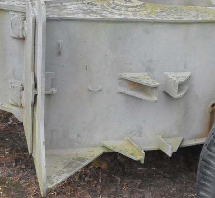
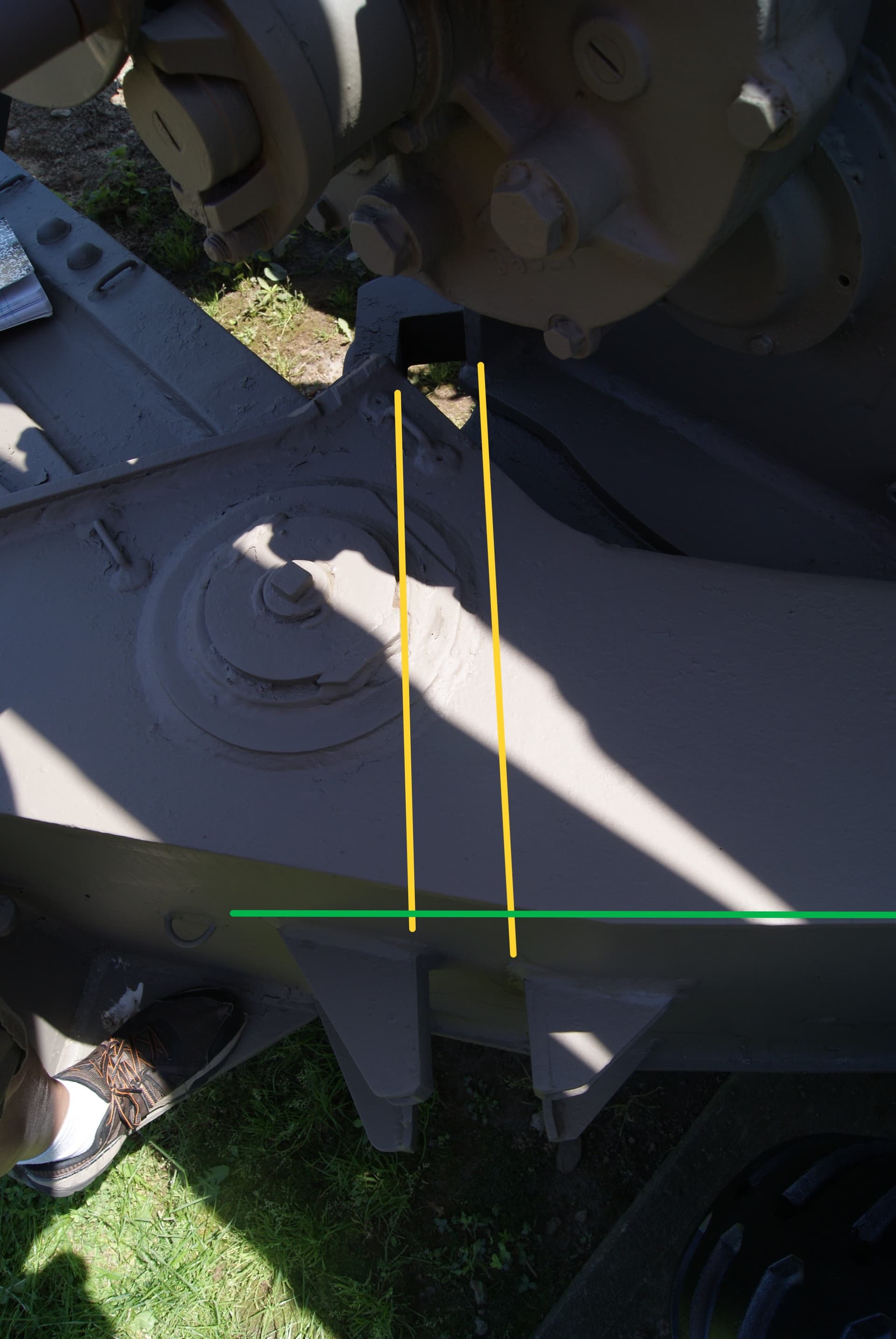
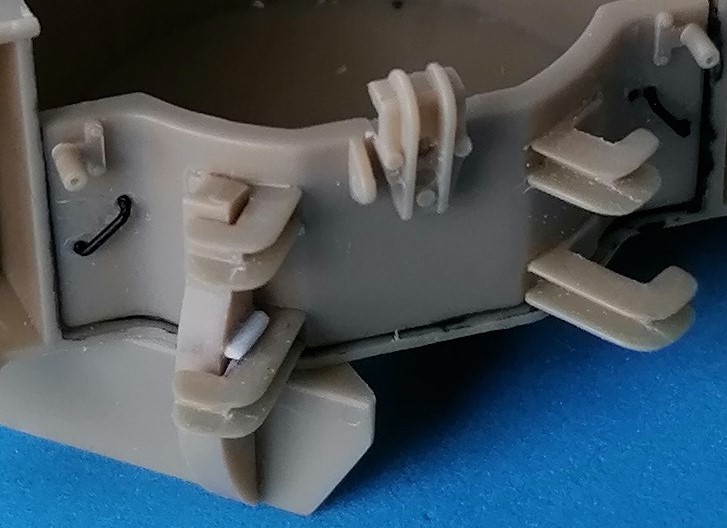
Which, together with lots of other pictures showing slits in the legs that go to the outside of the carriage and a steel bar welded to the others, convinced me that mounting the front spades worked something like this:
The spades are placed below the carriage, above or in the holes dug there, and pushed sideways towards the center until the legs are seated in the braces there, with the welded-on steel bars resting on top of the lower ones. This also moves the outer legs into place, where the keys are pushed through them, also resting on the lower braces. The effect being that the spades will be pulled from the ground when the carriage is being lifted.
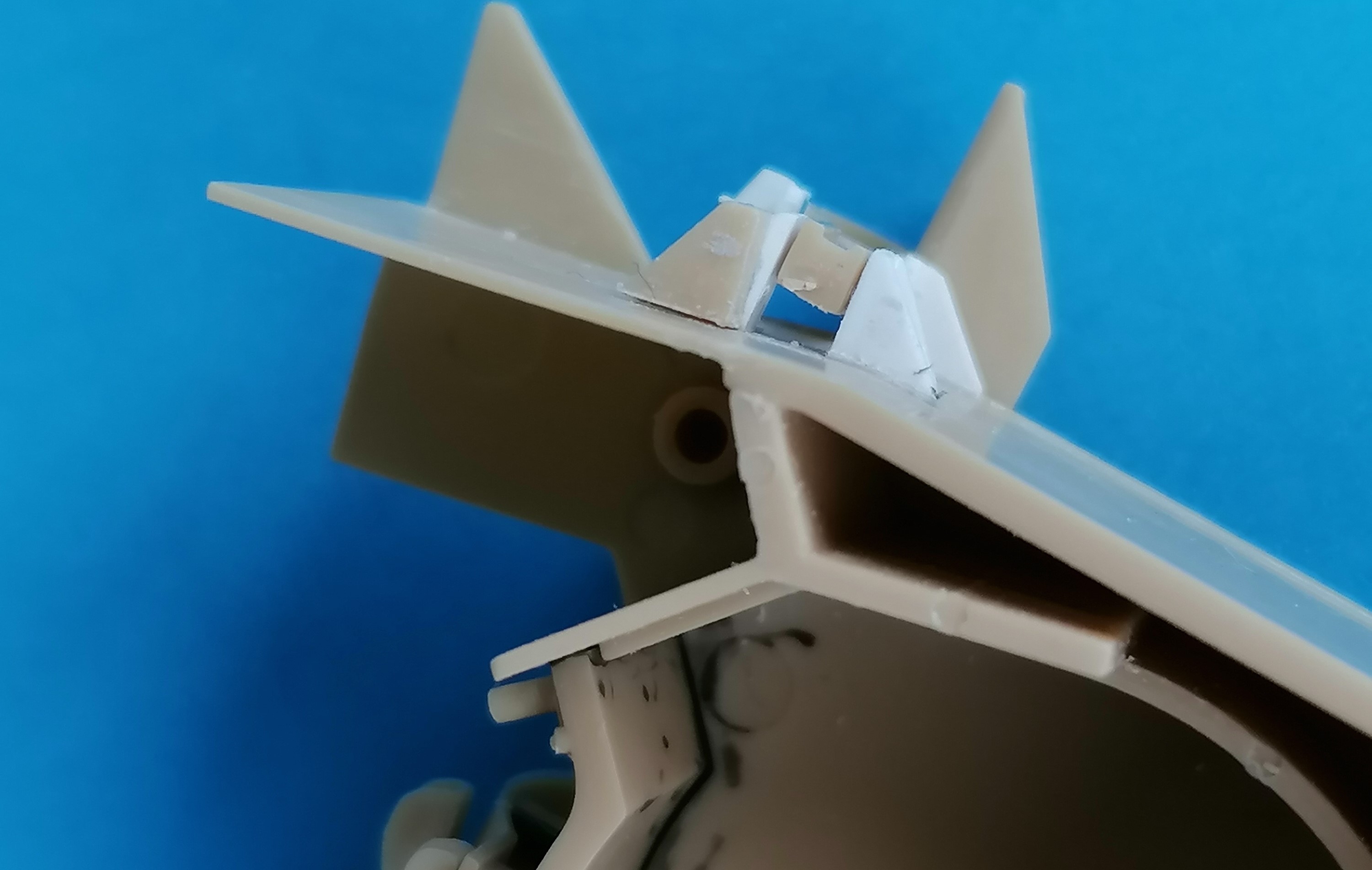
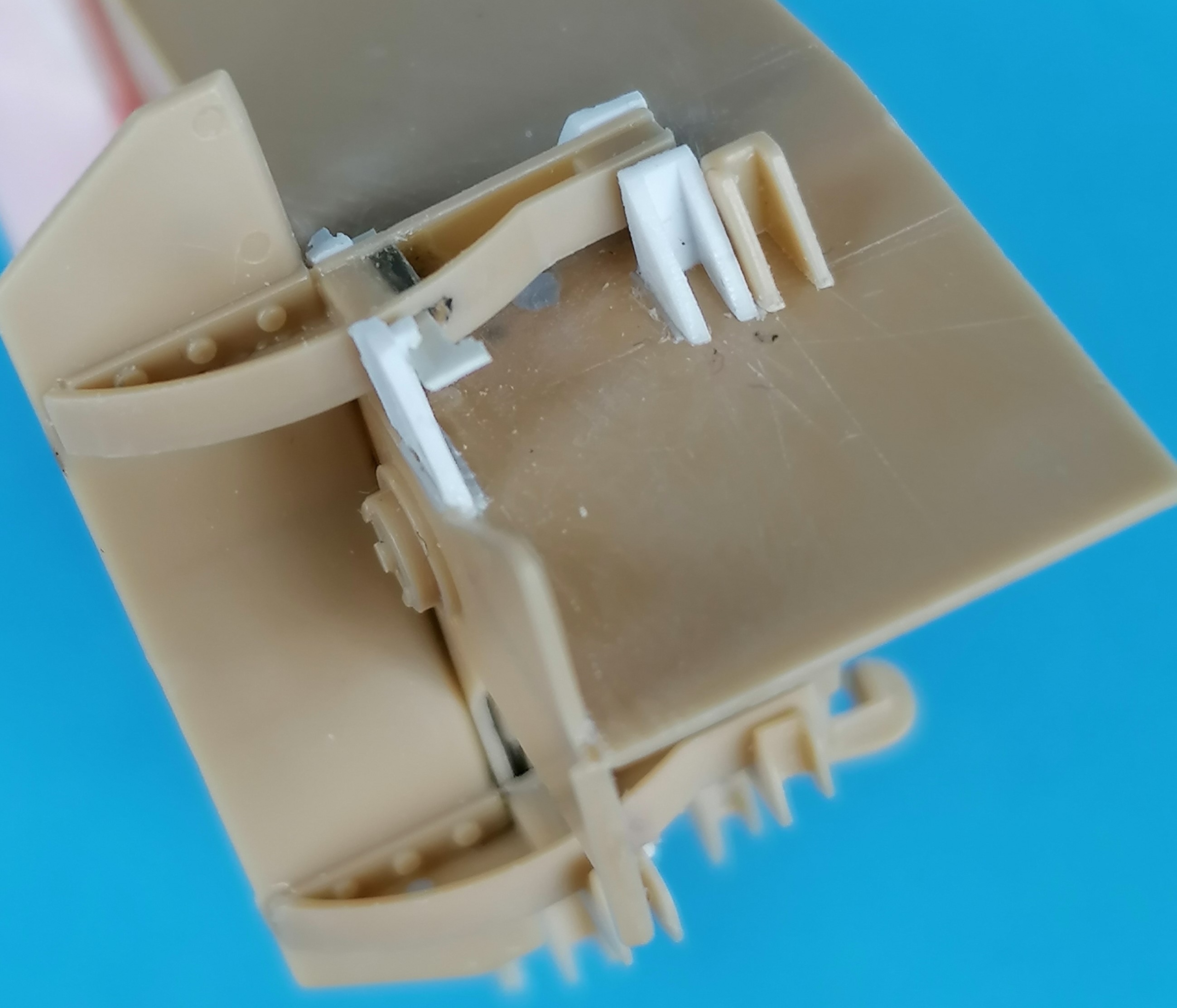
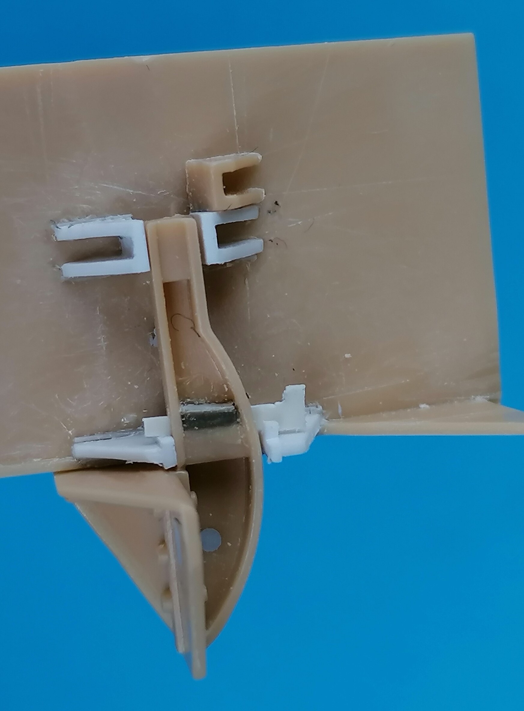
And that’s how I made them: I shaved off the wrong outside brackets and made new ones from 0.5mm strips and triangles; the result showed that for the position of the spades underneath the carriage, the support legs are about 1mm too far apart, while their distance is correct for stowage on the trails. (For the pictures, I placed the cut-off part next to my creations.)
To achieve the necessary space between keys and braces, the “channels” for the keys had to be heightened (on all four legs, see illustration in Kurt’s post,
#15 above) by cementing on pieces of 0.75mm styrene before the slits could be drilled and cut out with a jigsaw blade. The keys were sanded from 0.25mm styrene.
So now I’m waiting for someone who has been working with a 1:1 scale sample of this gun to tell me I’ve drawn all the wrong conclusions - but until then, I’m happy with what I’ve cobbled up.
Happy modeling,
Peter