The reinforcements to accommodate the Trophy B-kit have created a bit of work, with the rearmost upright of the turret side rails being the trickiest. Getting those webs even close to right was challenging. Of course, neither side of this part is symmetrical!
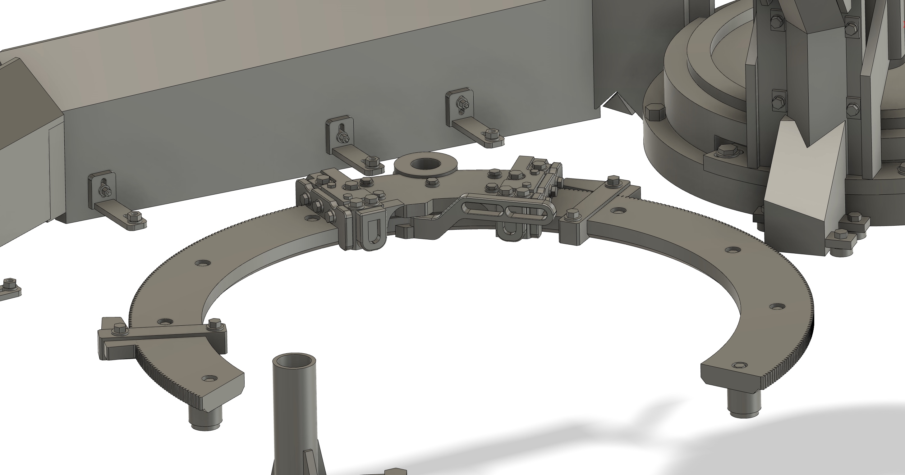
That’s looking very nice. I think you’re got the right size on the teeth. I have no idea if you can see it in 1/16, but the teeth to not come to a point where they meet on the inner portion. They have sort of a “step” over to the next toorth. If you expand this you can see what I mean:
Thanks @18bravo - yep know what you mean, the “flat” between the outer surface of the teeth is mirrored on the inside surface. I chose sanity, so it’s close but not 100% prototypical. Working to 0.395 of a degree for a 30 degree segment was tedious enough for me! Nice pic, btw.
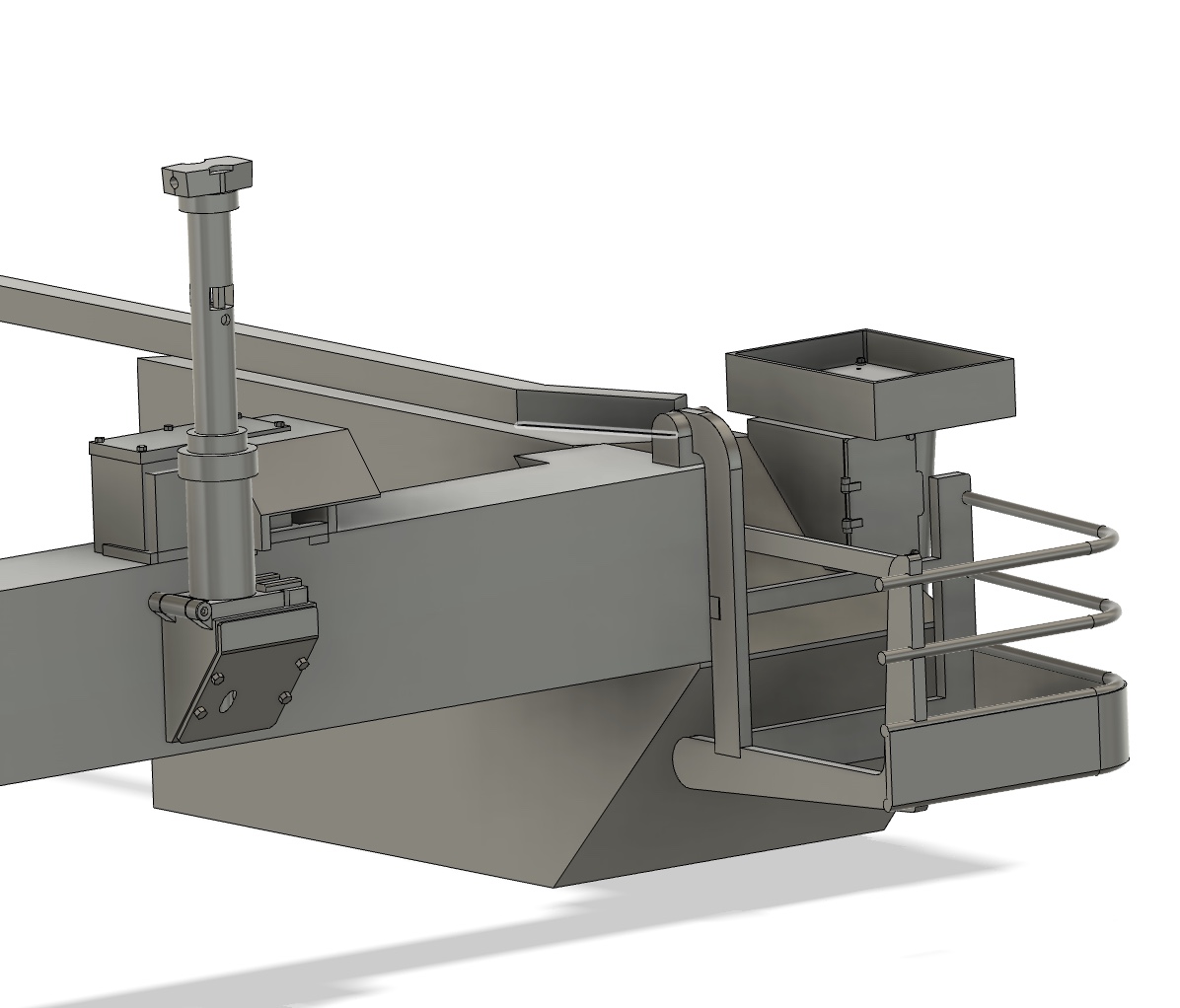
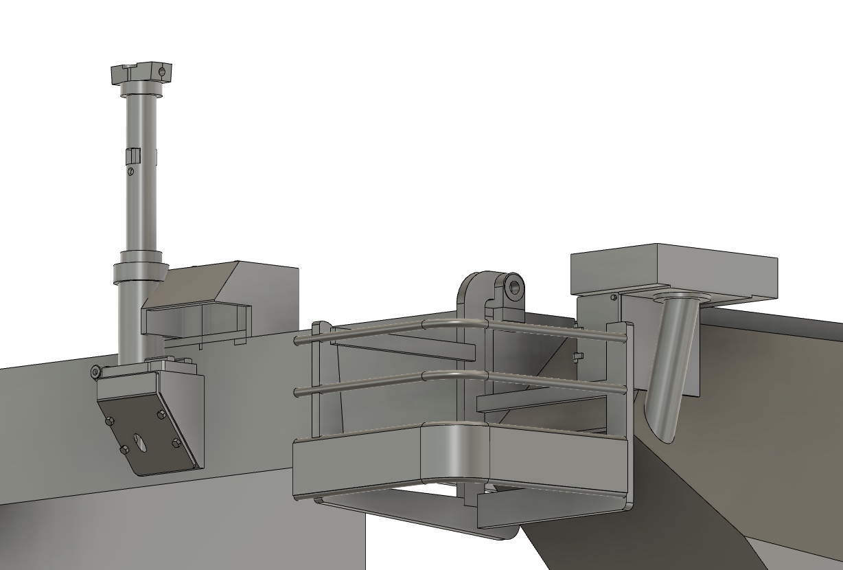
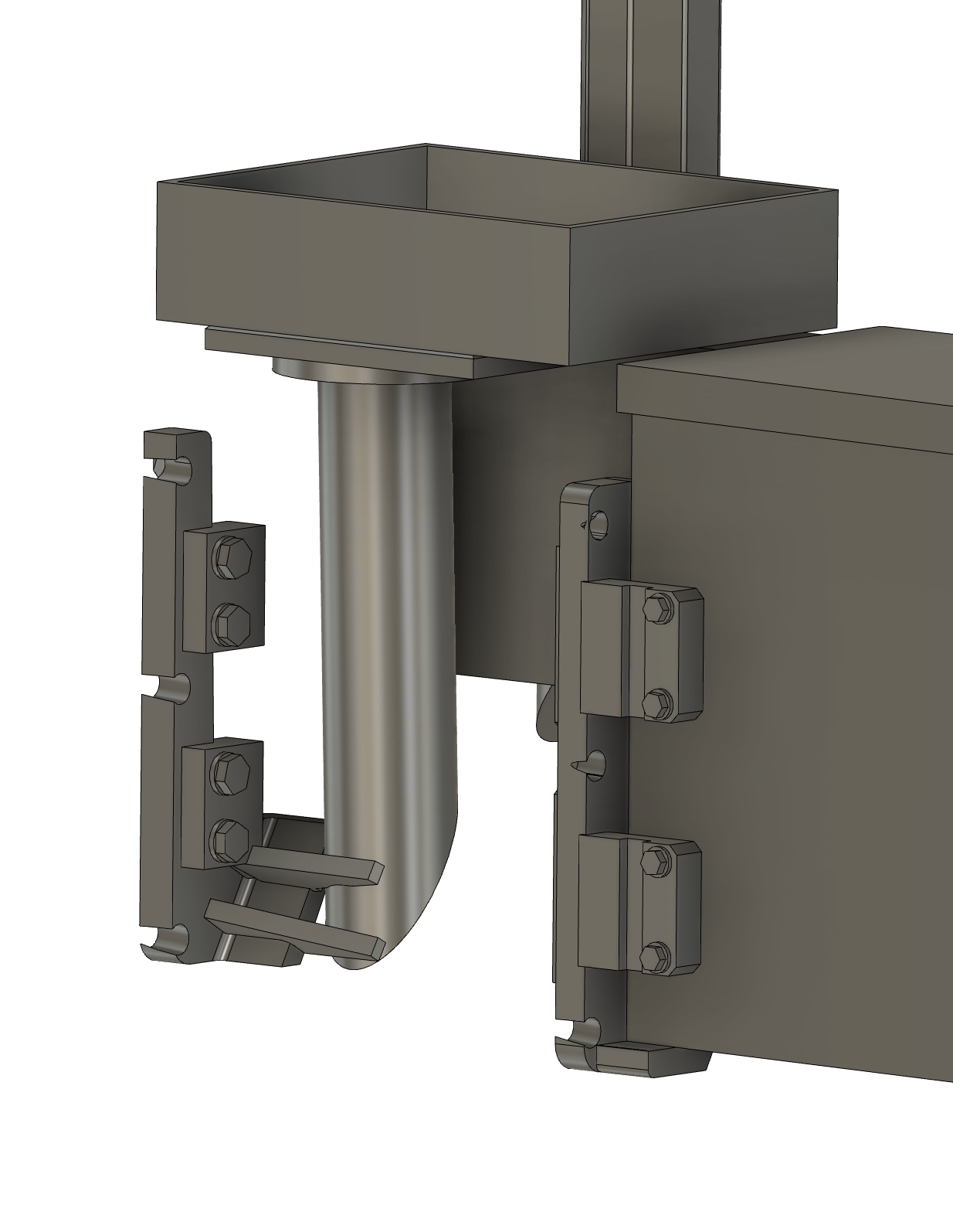
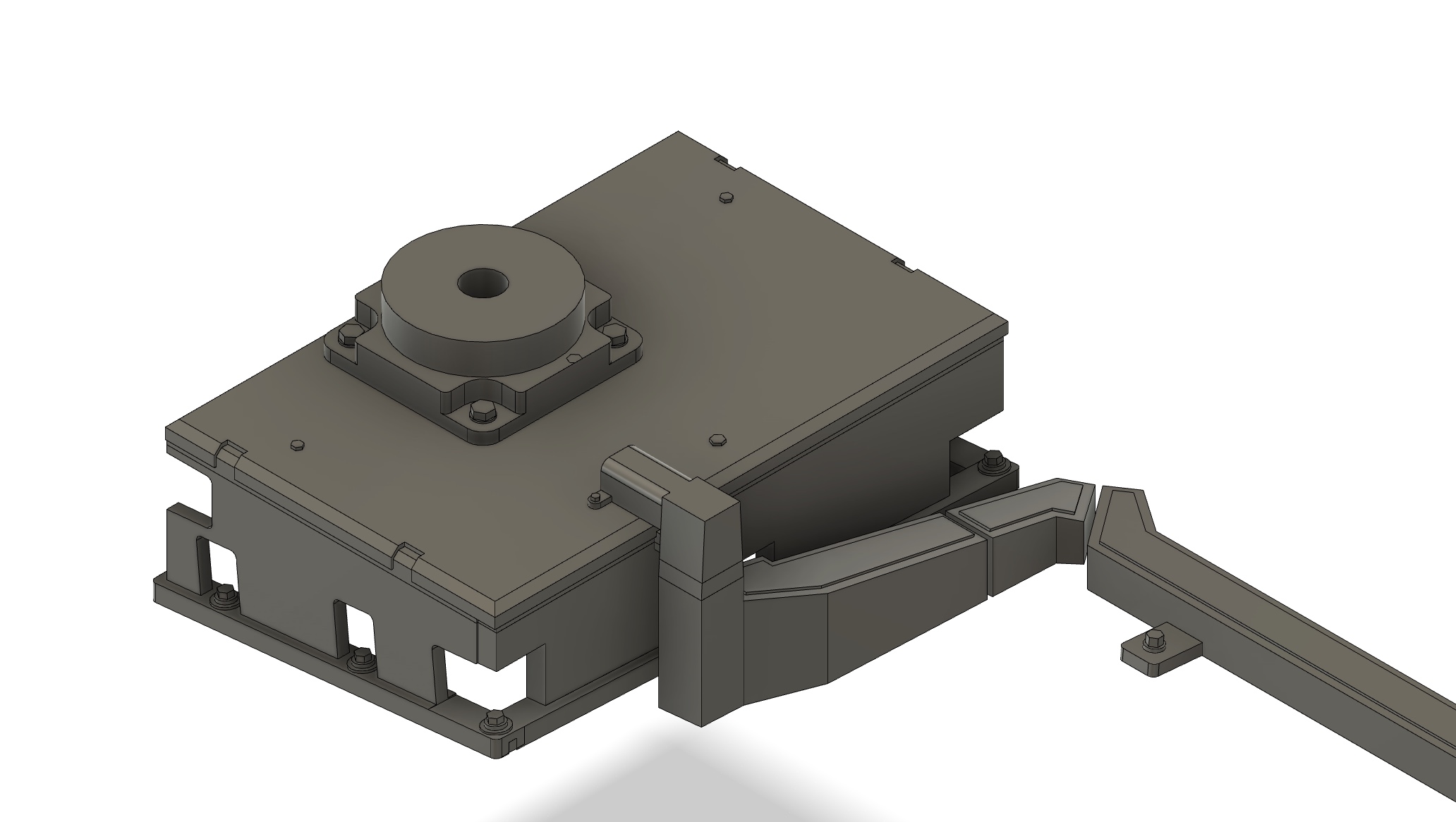
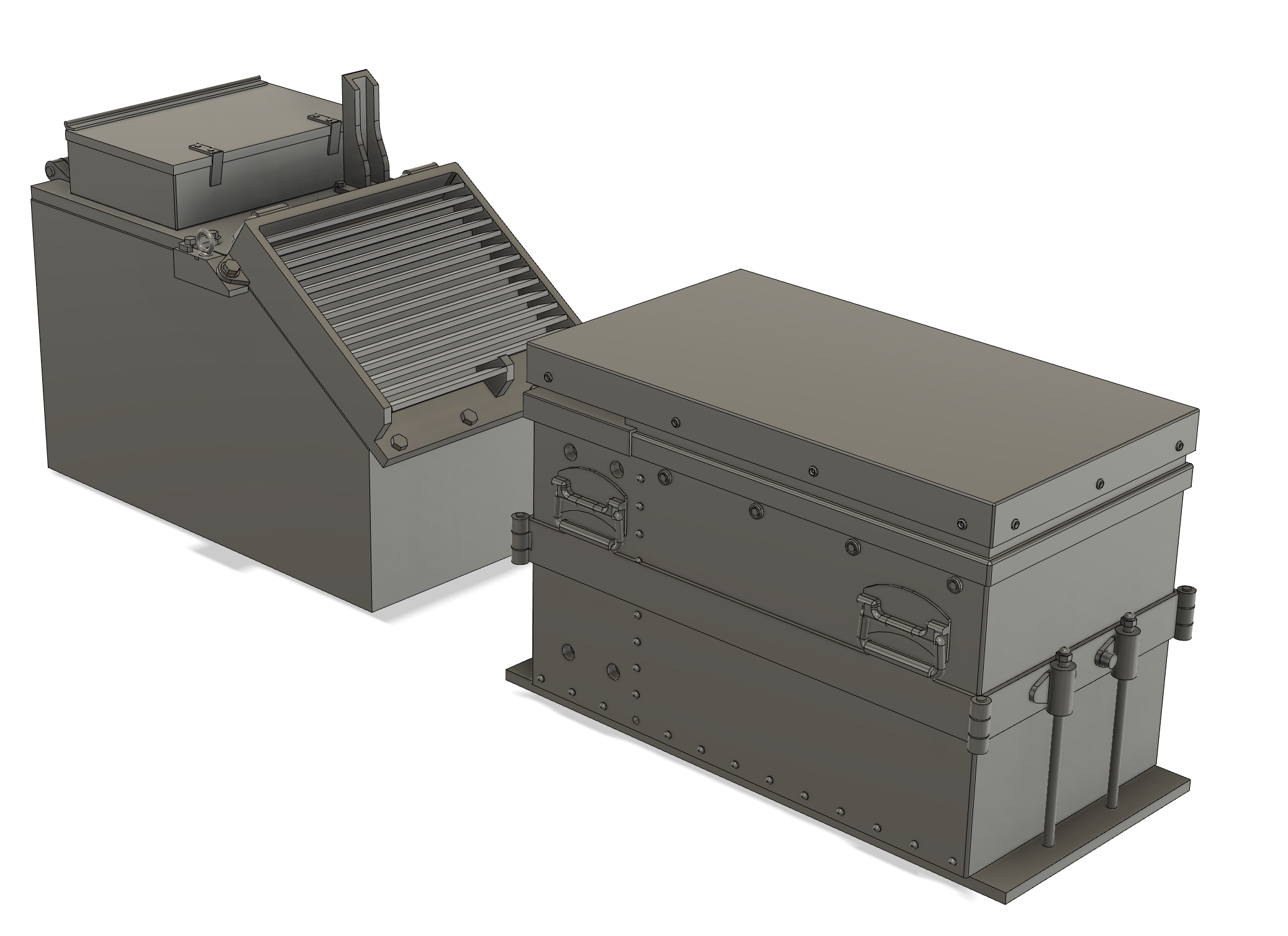
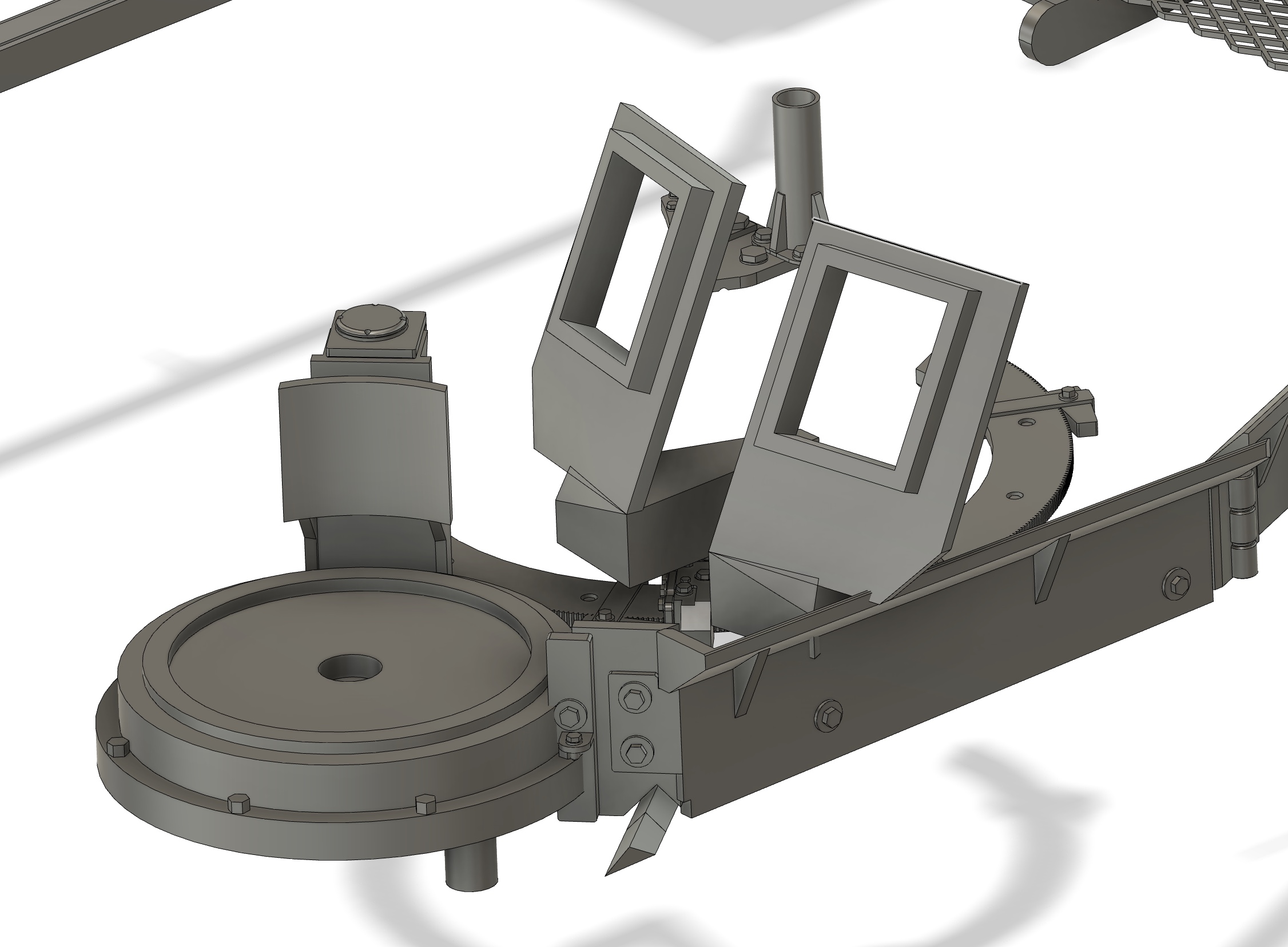
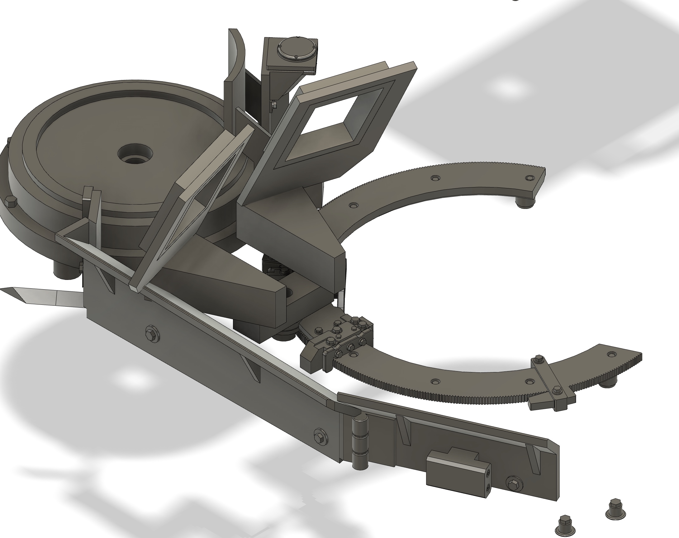
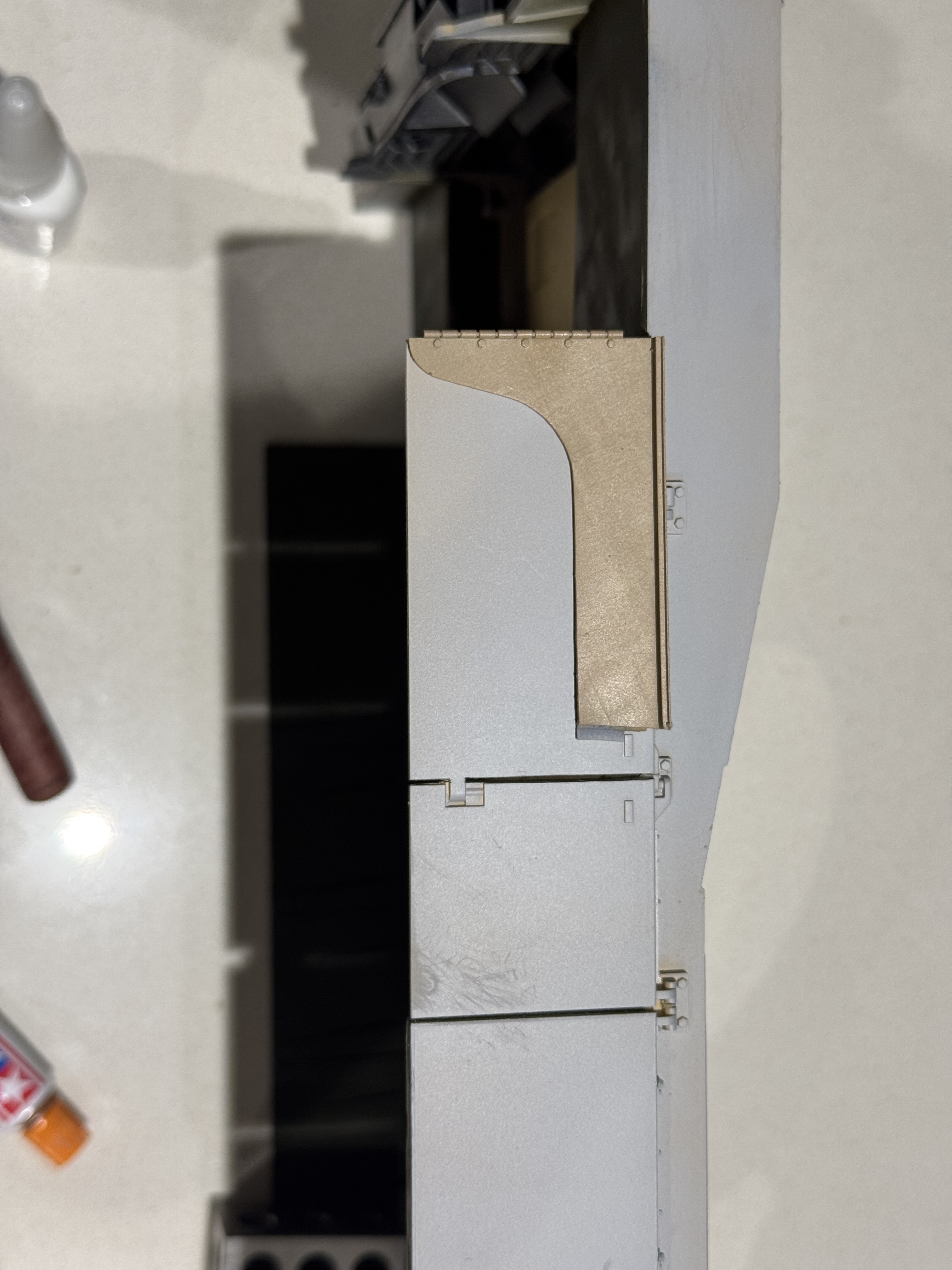
The Blue Force Tracker box &, more specifically, the patch panel underneath, is at the intersection of three surfaces at a five degree, 30-degree, & 45-degree angles. Add the bustle rack to the equation, & it gets complicated quickly.
As such, I’ve mocked up digital twins of some of the components. These are then printed & validated. Sometimes they’re more distant cousins than twins, so some refinement is needed.
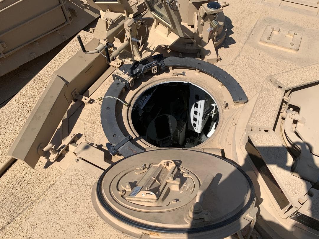
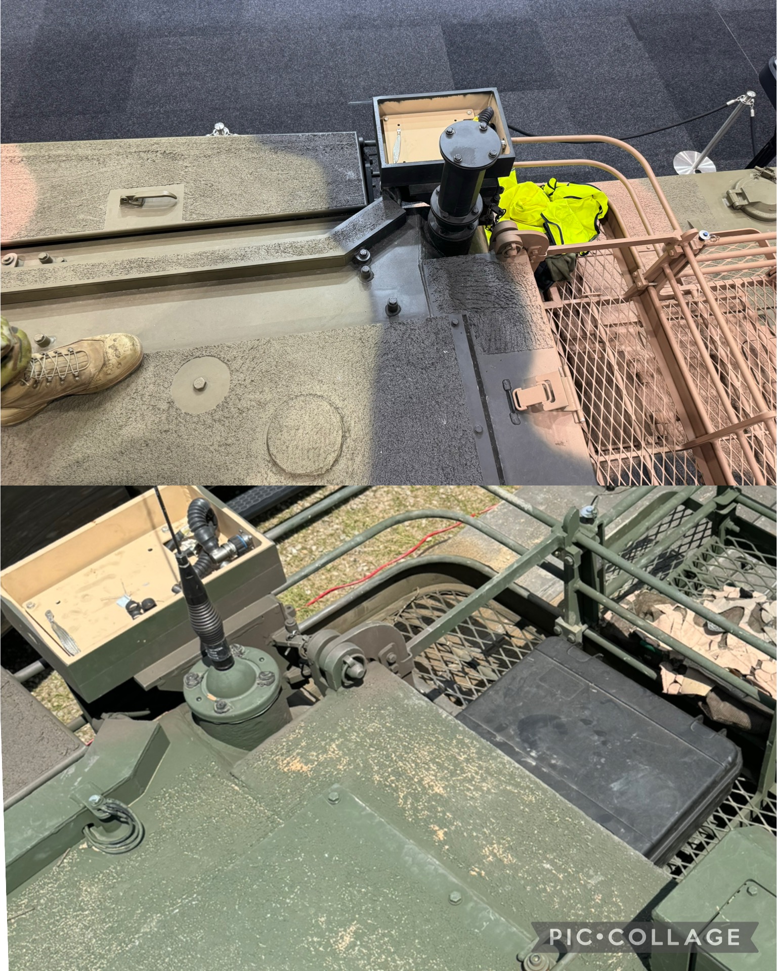
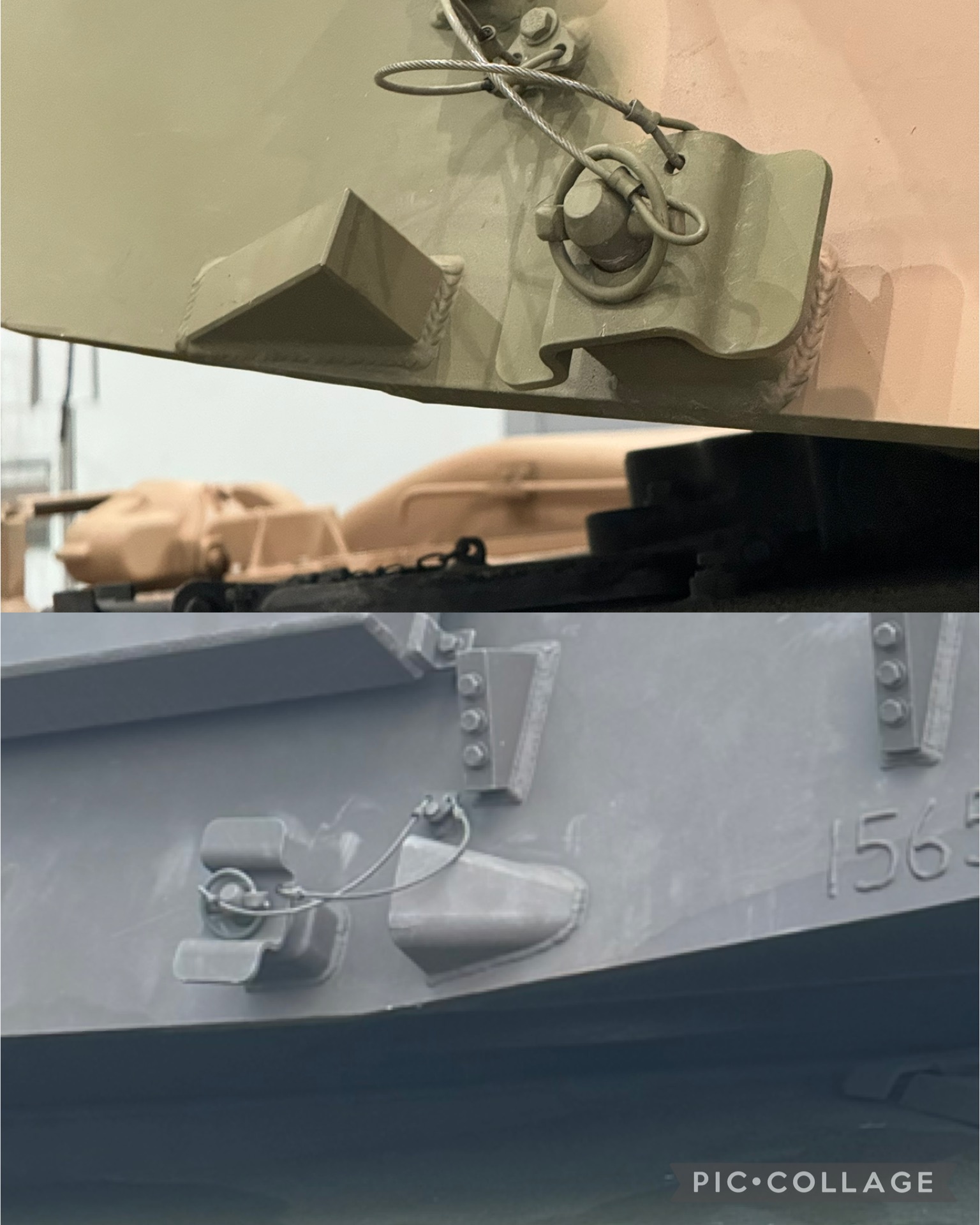
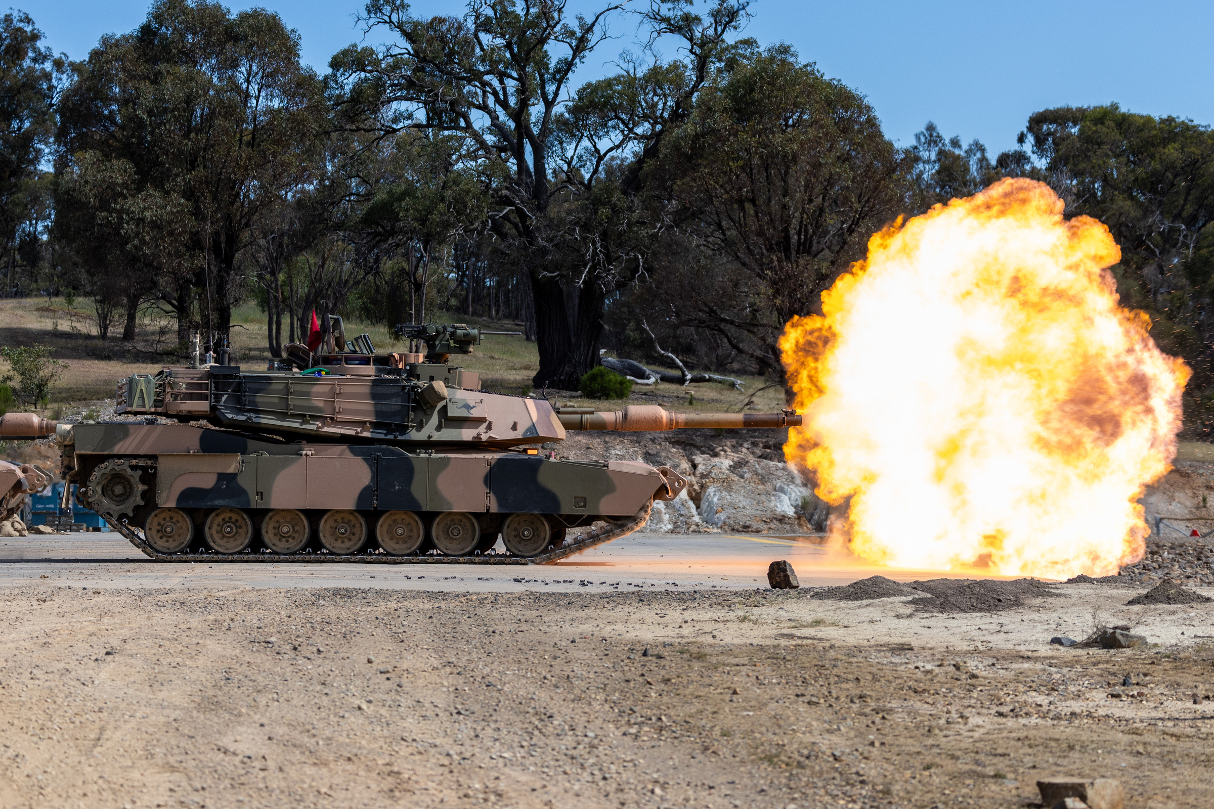
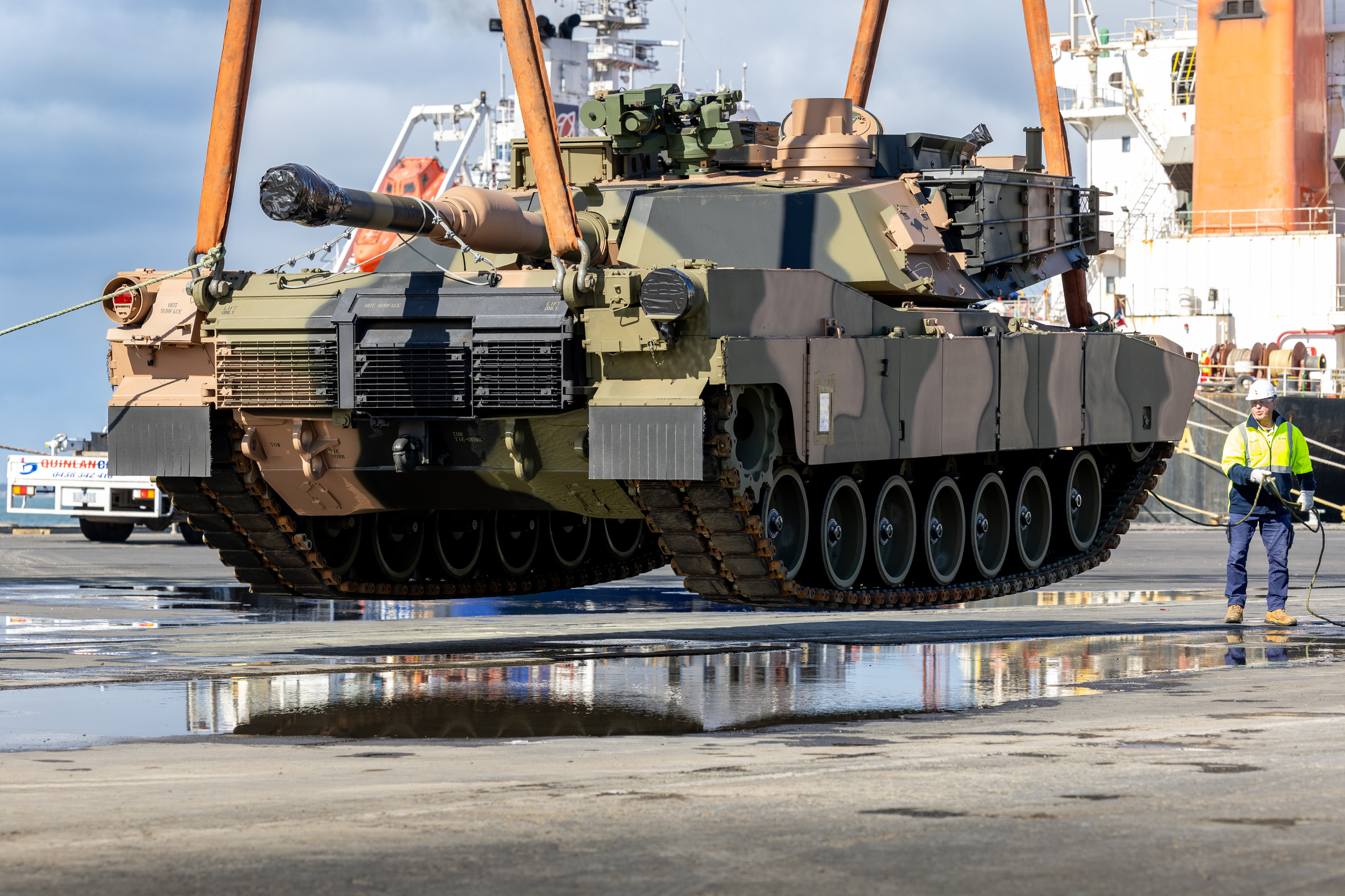
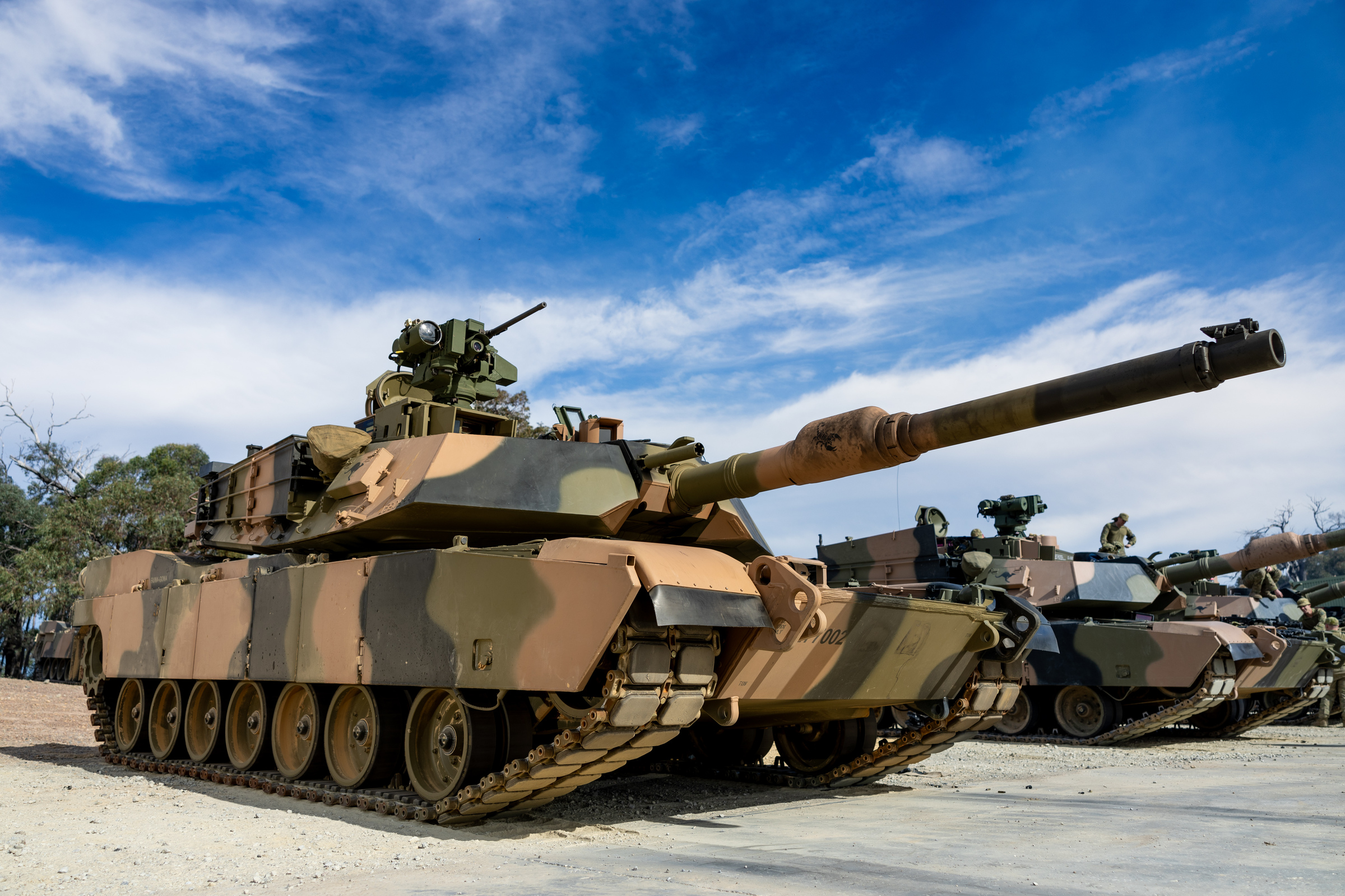
The differences between tanks fitted for Trophy & not continue to become more & more apparent.
Here’s a comparison between a US Army SEP v3 I was climbing on in Georgia (state-type) in April vs. the Australian one I was all over in Victoria, Australia.
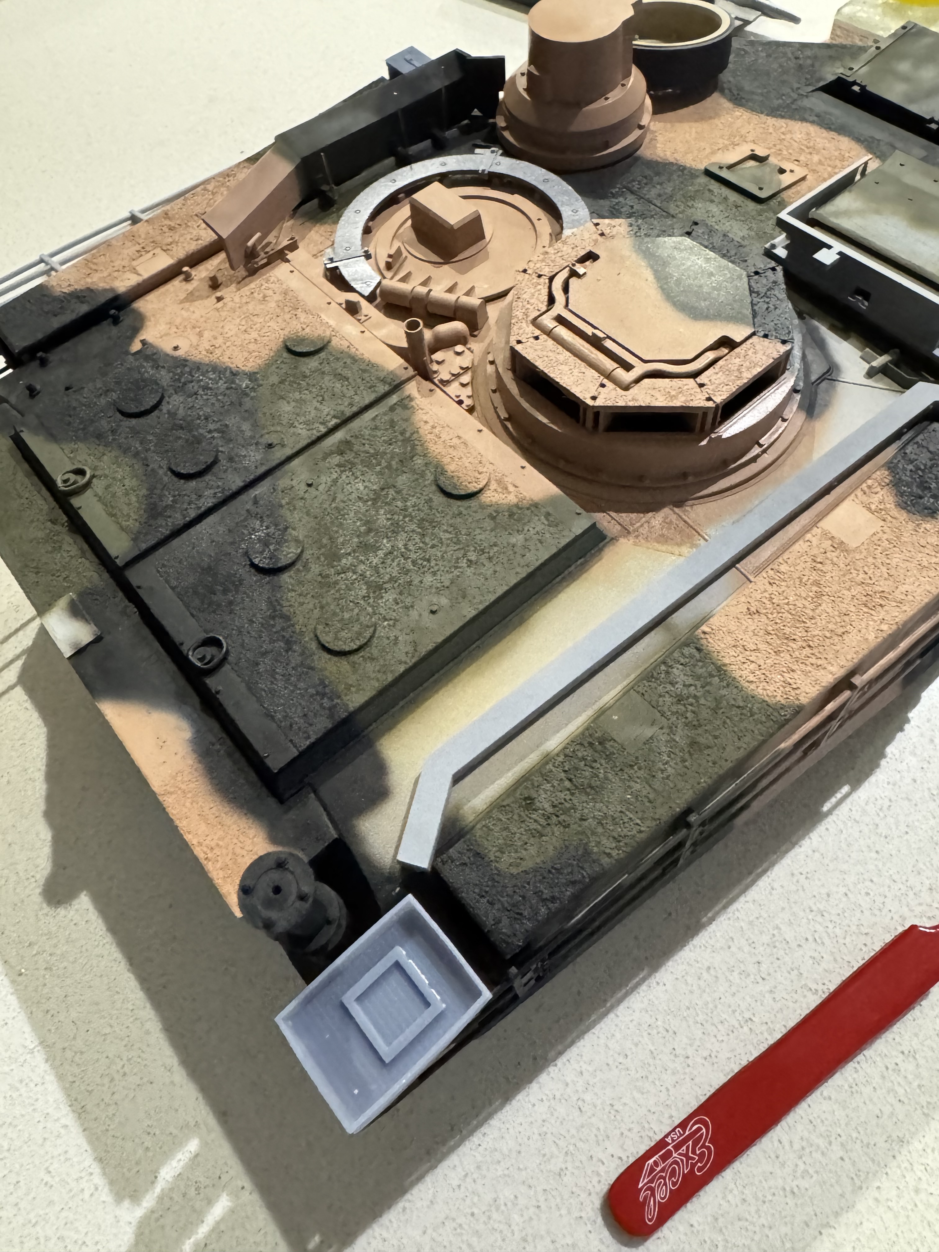
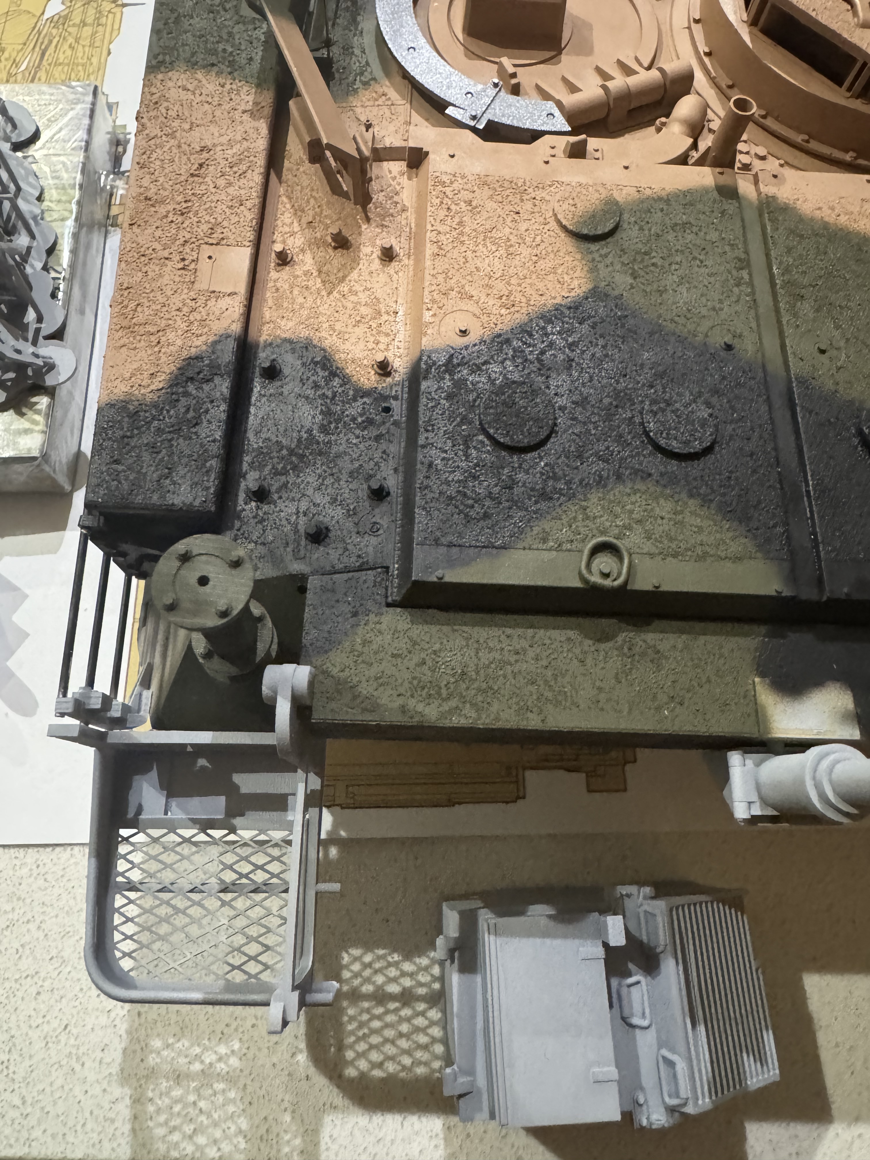
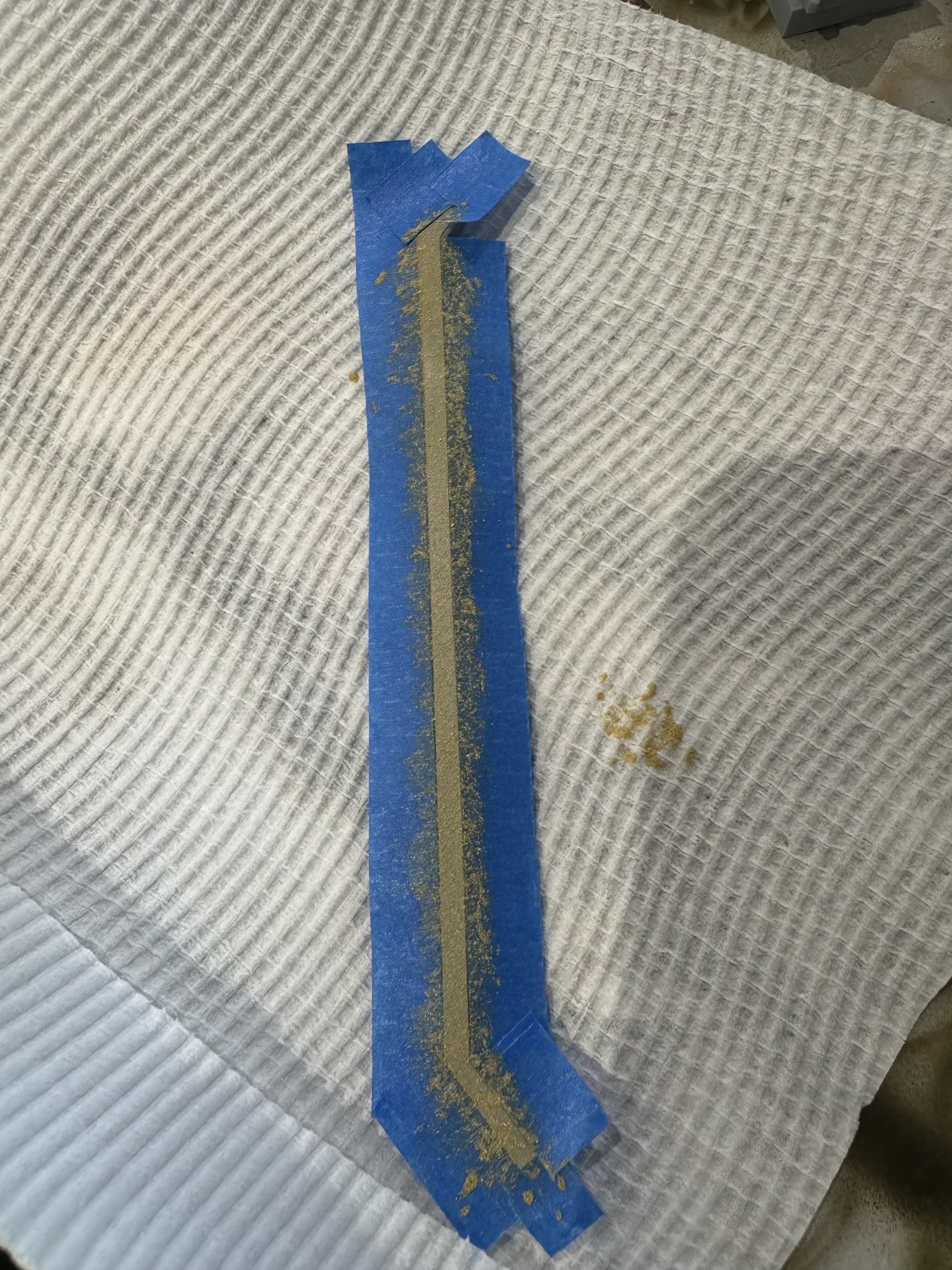
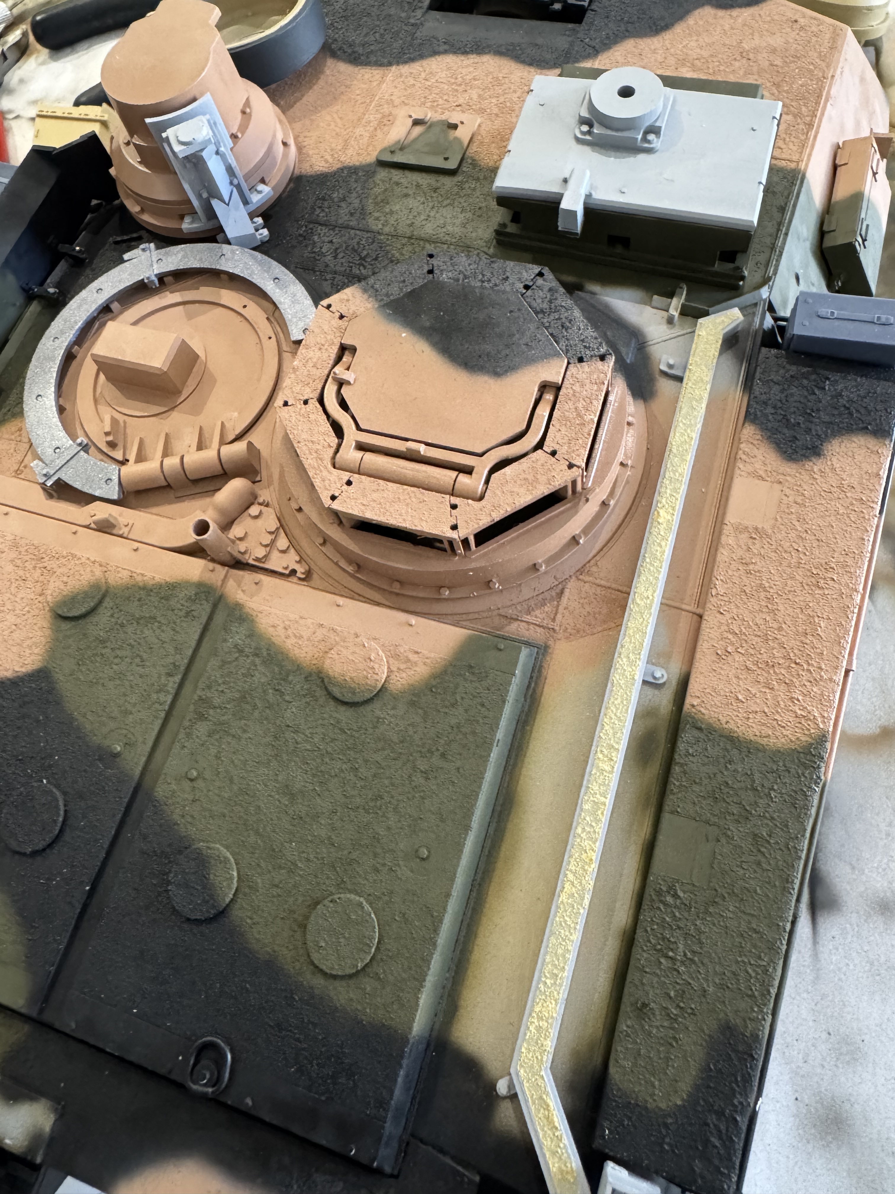
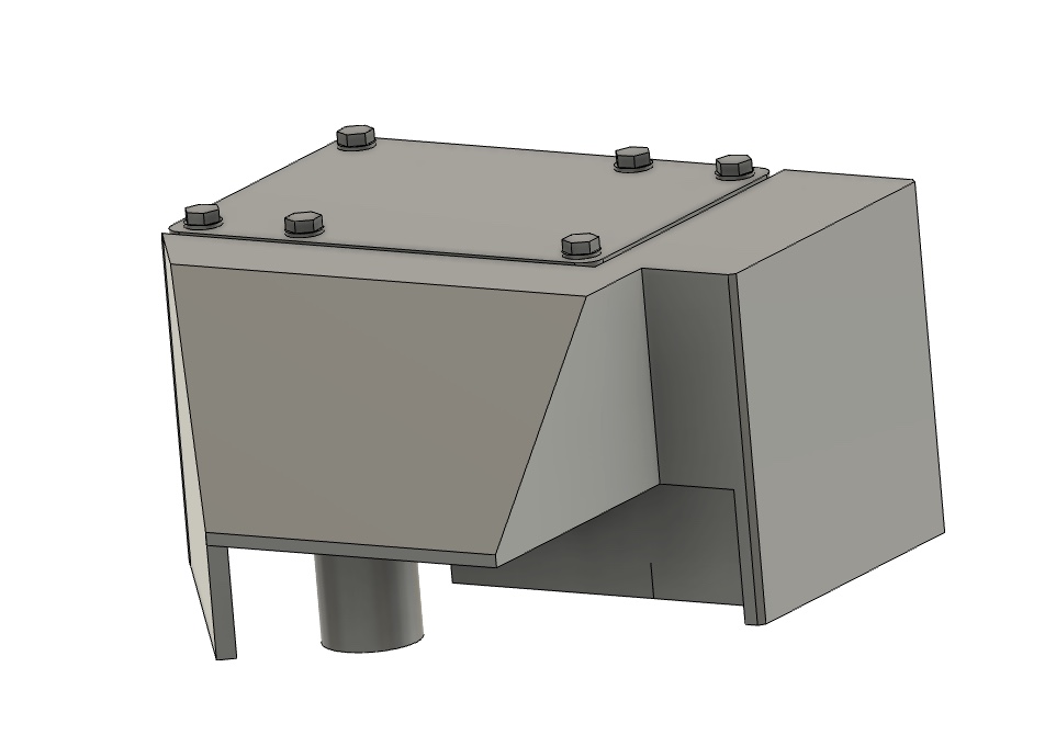
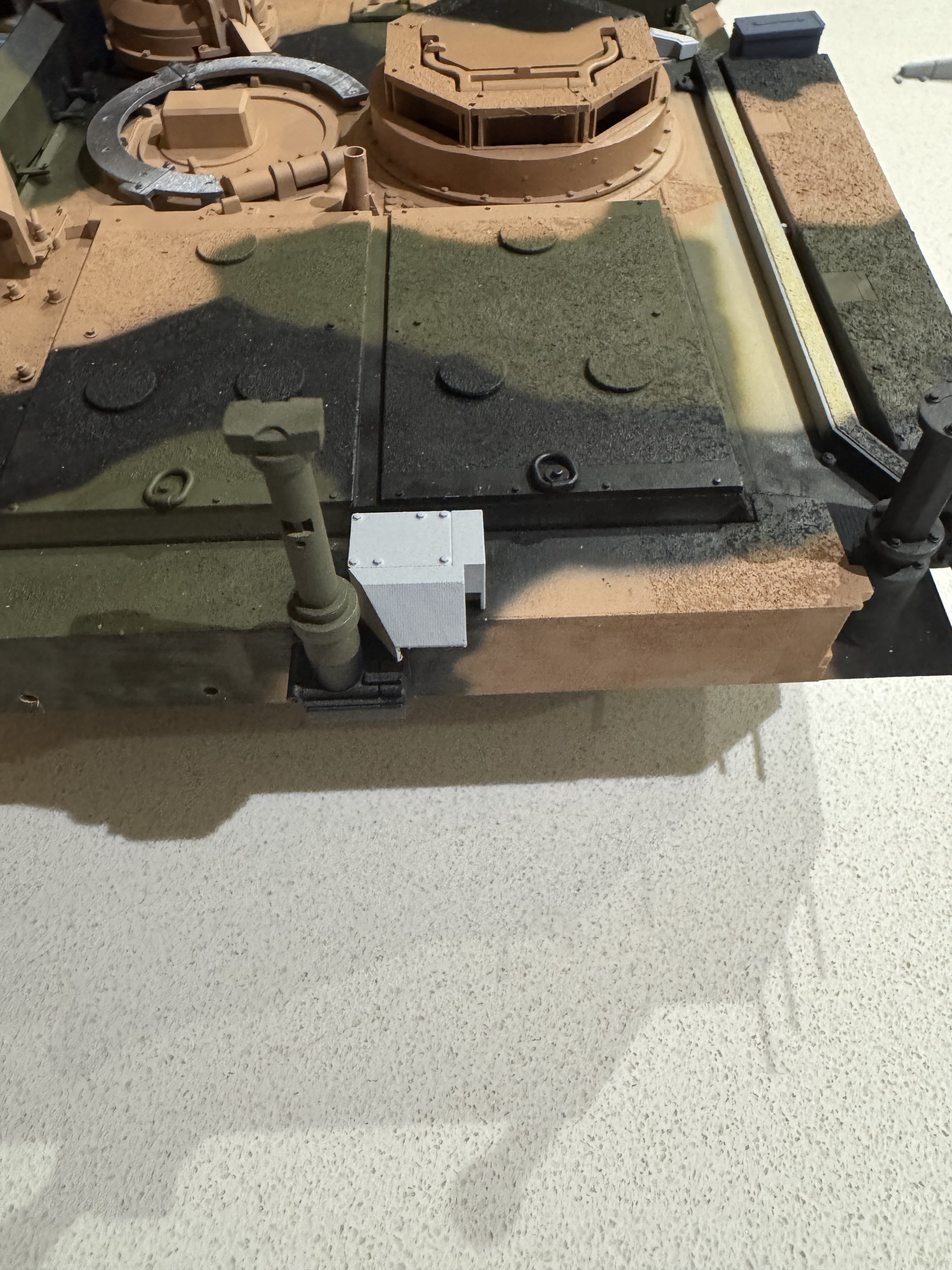
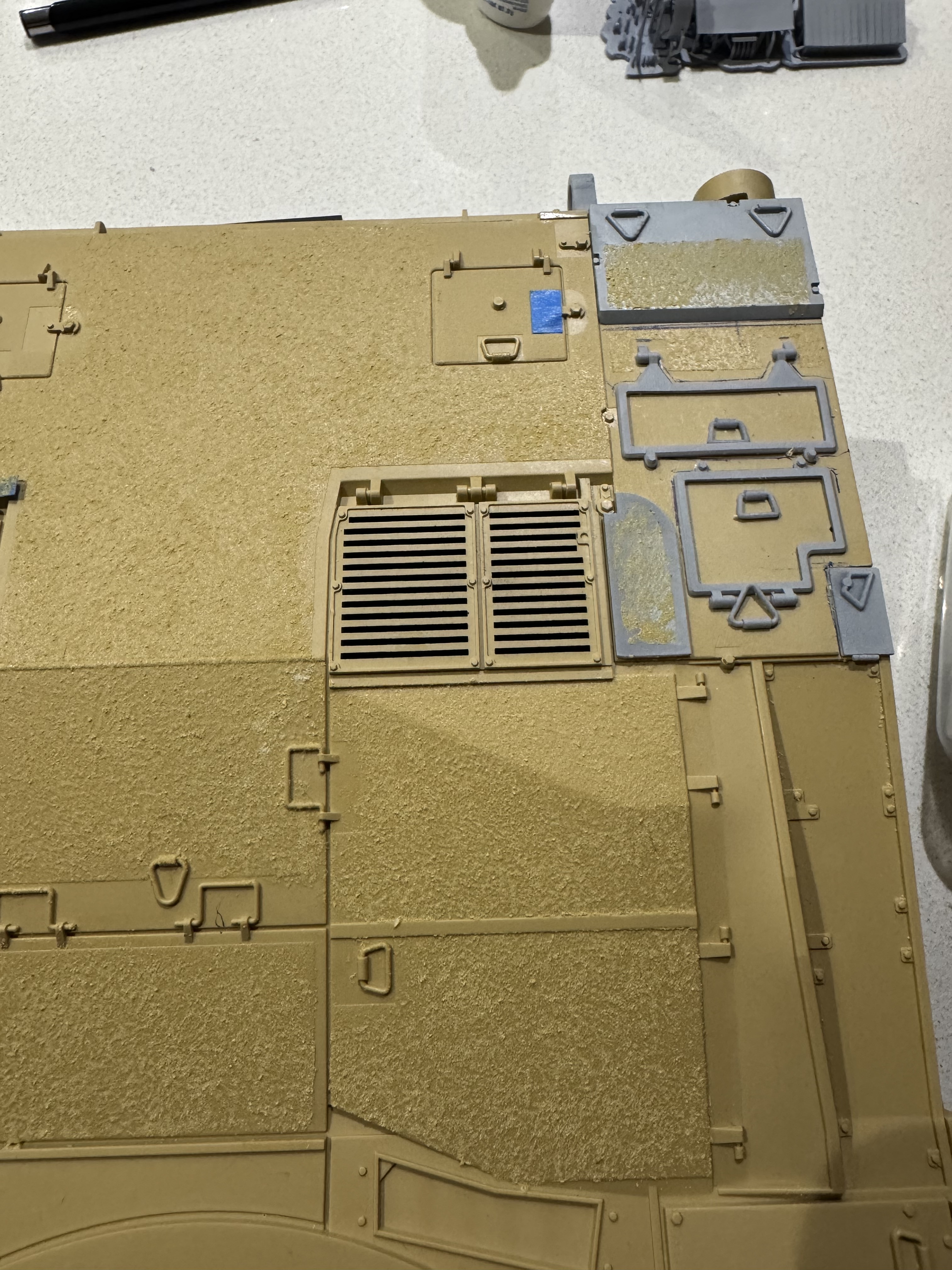
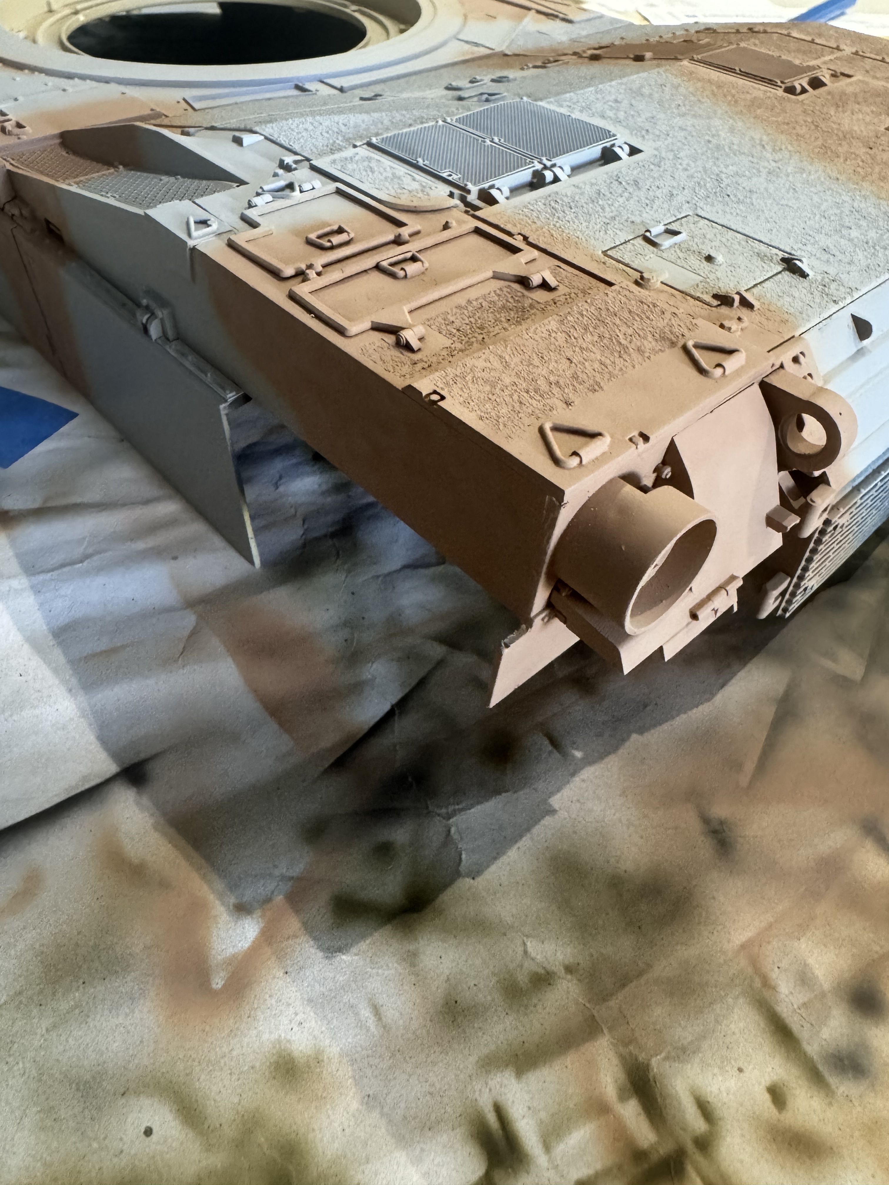
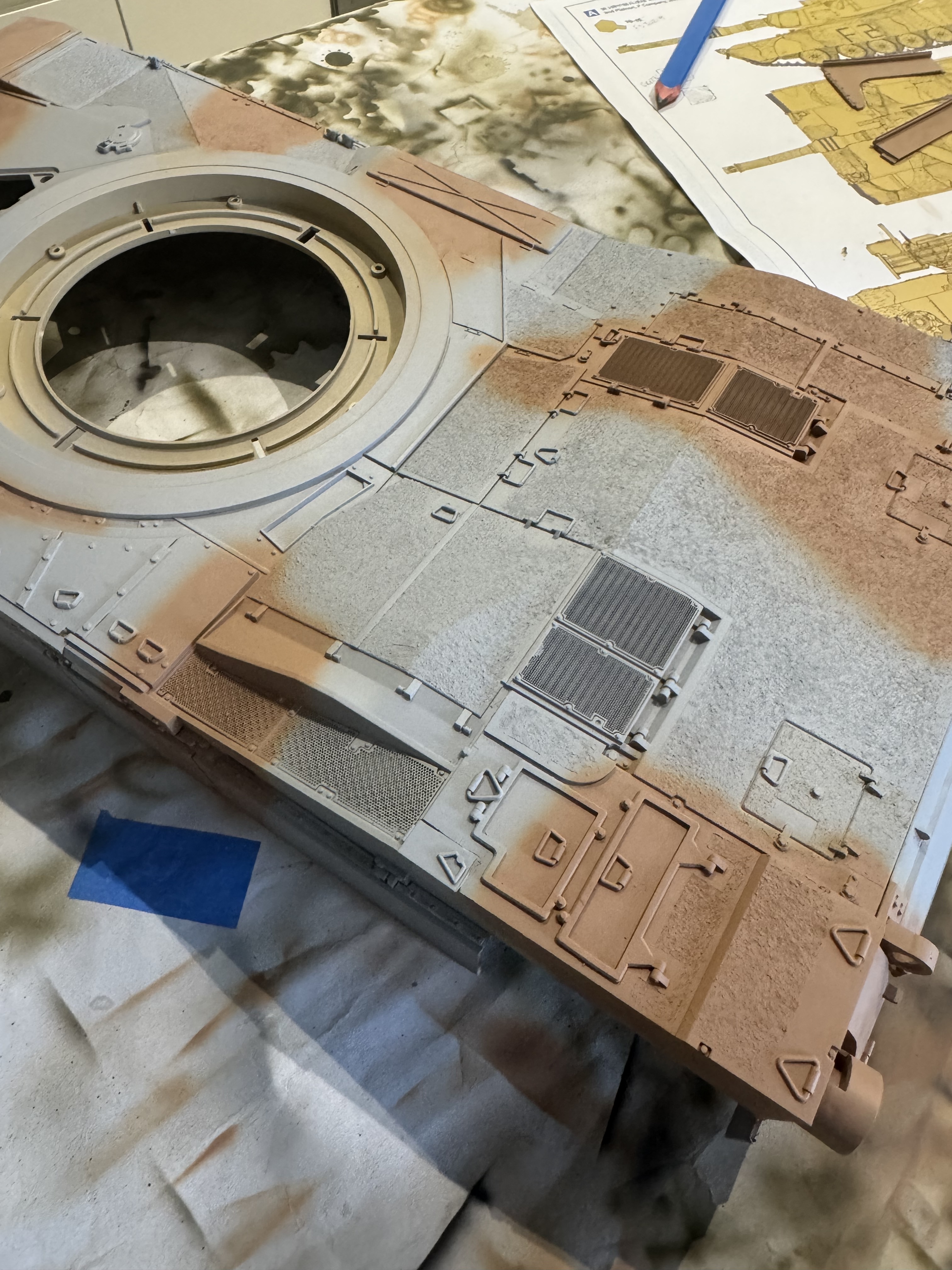
Printed the updated BFT conduit, then added anti-slip texture via Tamiya textured paint. Will have to learn how to add the texture digitally one of these days.
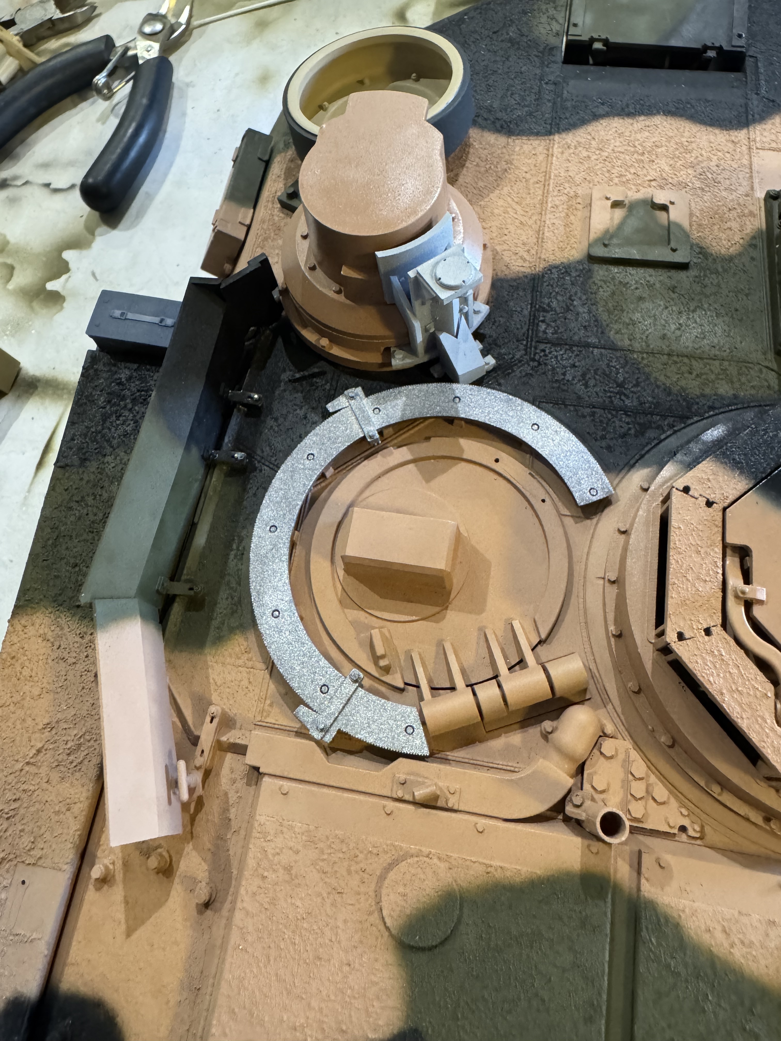
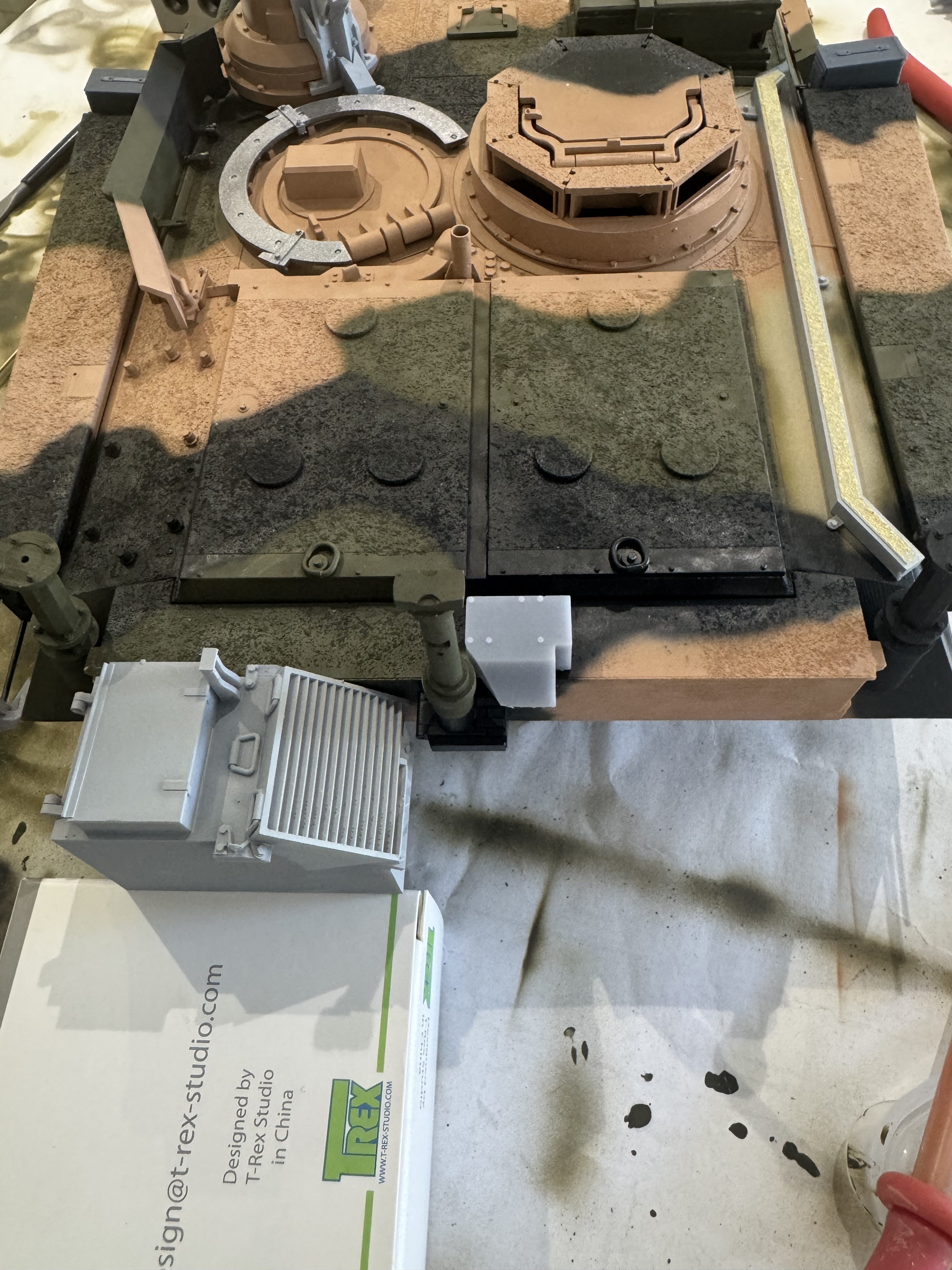
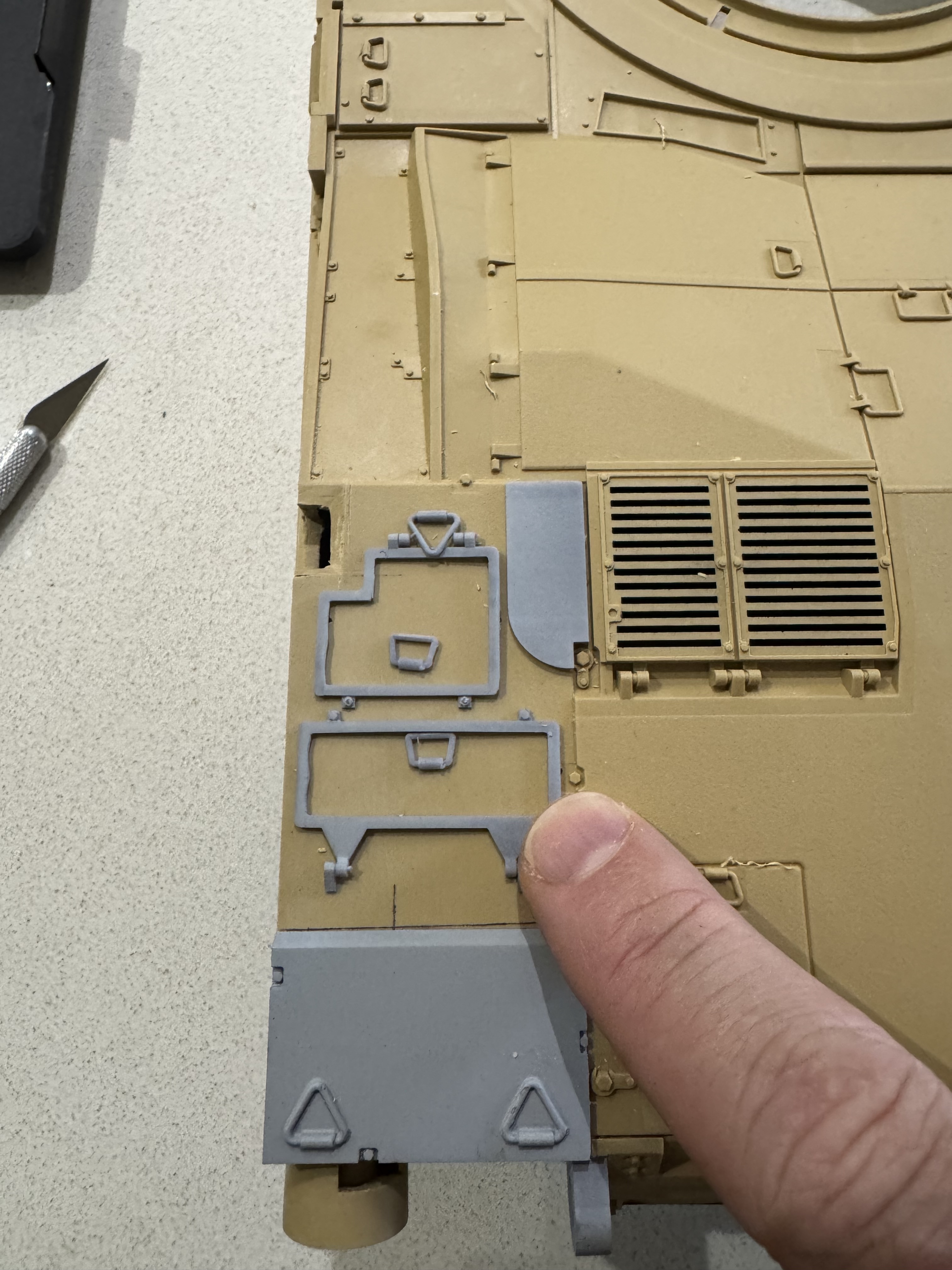
Test fit of the VCSU, using the kit holes for the APU. Need to shift toward the centreline by 1.5mm to clear the bustle rack. Also visible is the form factor test of the patch panel adjacent the cross wind sensor.
Returning to the upper hull to align the progress.
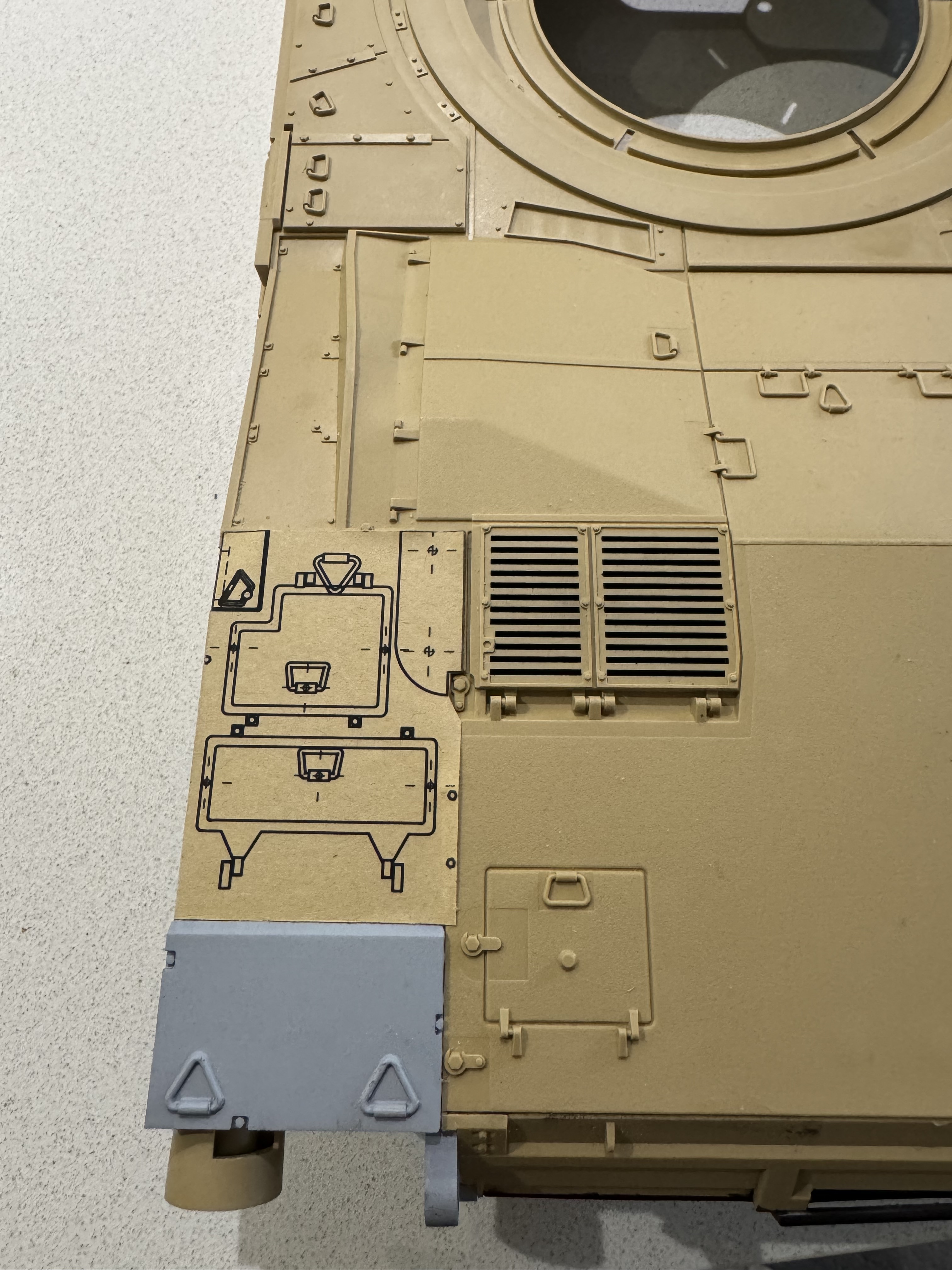
I’ve recently discovered self-adhesive printer paper. To use this for accurately plotting location holes to be drilled, I’ve turned a few of my designs into drawings. I then print the pdf, cut it out, and put it in position.
There’s still some front end work to complete - power outlet adjacent the driver’s hatch, ECM conduit on the front right of the hull, & the hull tow cable anchor point.