In your earlier post, you mentioned/shown the old & the new transfer case. Is the old transfer case part of their Scud missile transporter kit? I just purchased a scud transporter box earlier this summer and have no knowledge of this kit accuracy (beside its cool) and your comment got me curious.
As for this new kit, I might have to look into getting one during a Black Friday sales this year.
I can’t say how the Scud kit stands these days as I don’t/never owned that one. Sorry. Also cannot comment as to if the old 537 tractor has ever been updated.
Of course on the Scud I assume the driveline is only visible from underneath so it may not matter to some.
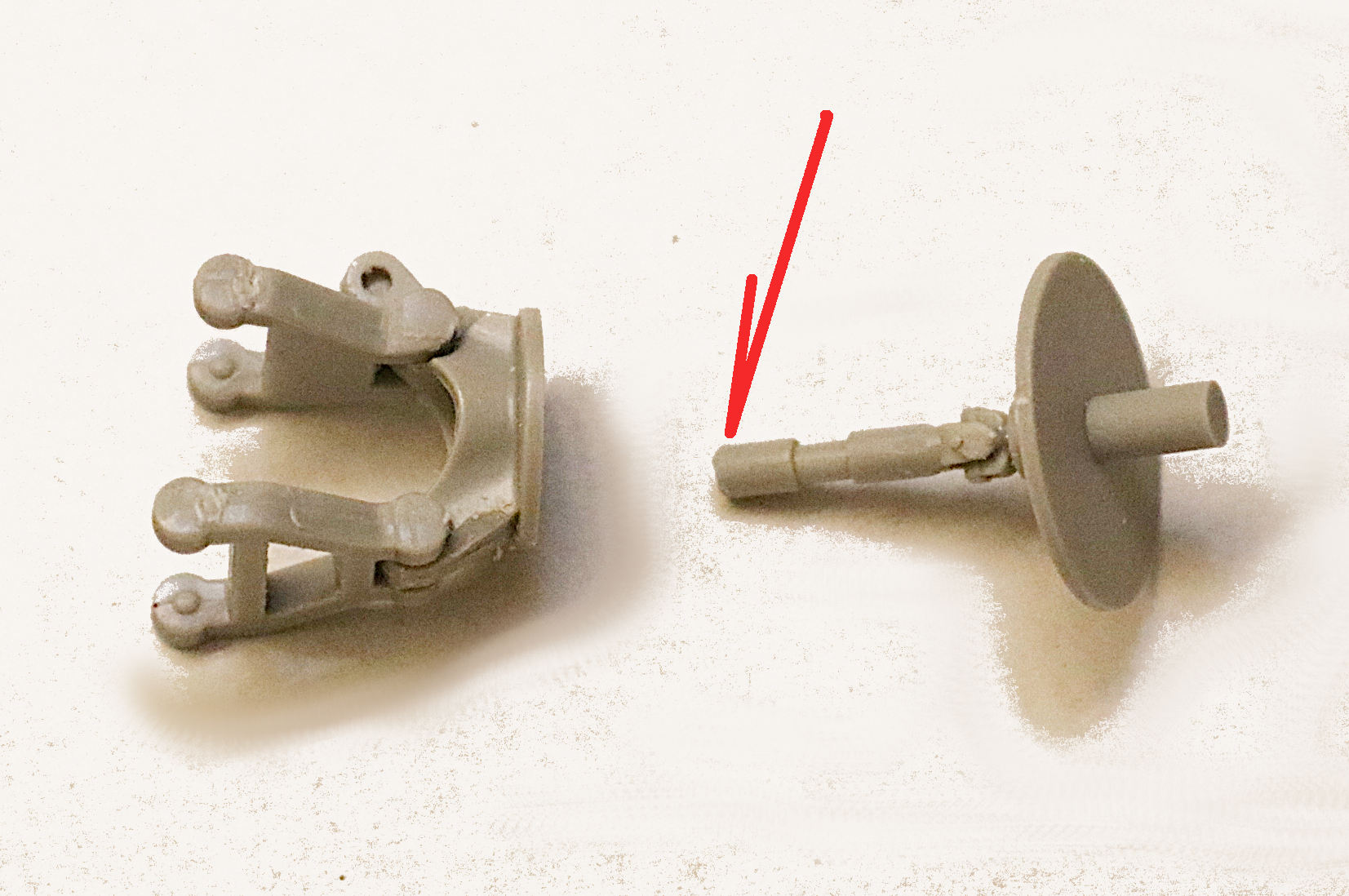
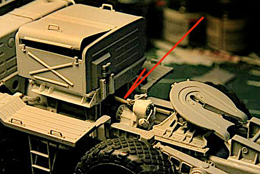
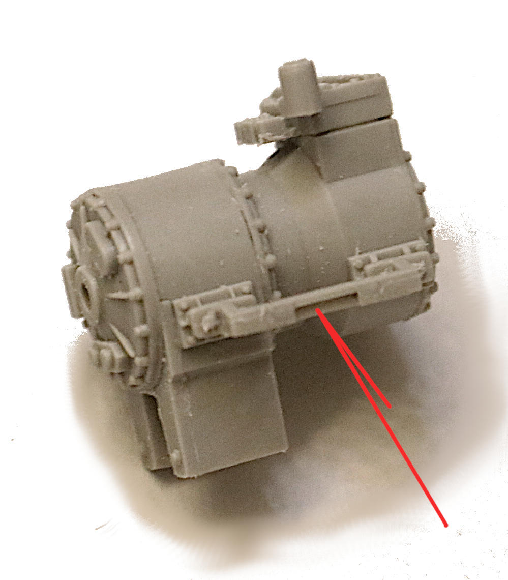
The instructions have you start on the rear two axles first and so far that is all I have completed. Trumpeter would have you build four A-arm assemblies as seen in my first photo below.
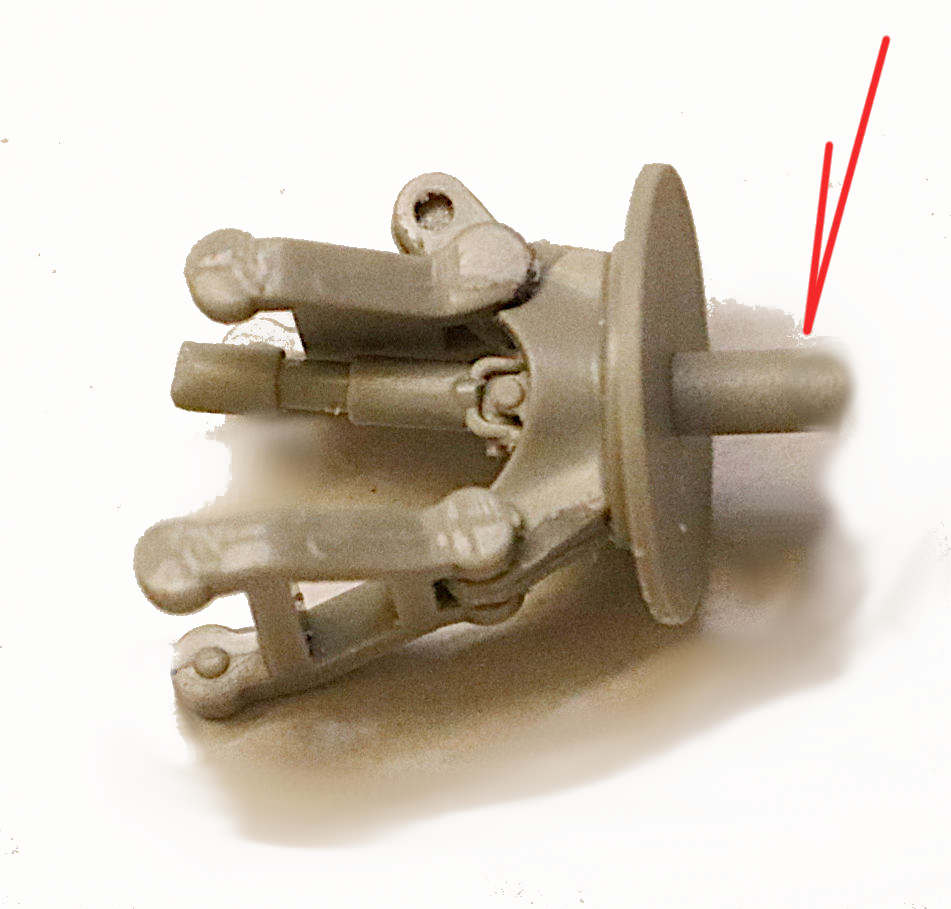
I HIGHLY SUGGEST that you break this step into two assemblies as seen in my second photo AND that you shave about 1/32nd inch off the end of that half shaft. (Red Arrow)
The A-arms have functional hinges here and are a real bear (insert stronger language) to snap together. It is much easier (that’s a relative term) to snap them into the chassis mountings if the brake discs and the half shafts ARE NOT yet attached.
NOTE: Both the brake discs AND the half shafts are keyed to go in ONLY ONE WAY - so please be aware when installing!
Springs! How do I get to install the springs? - NO ???
Edit:
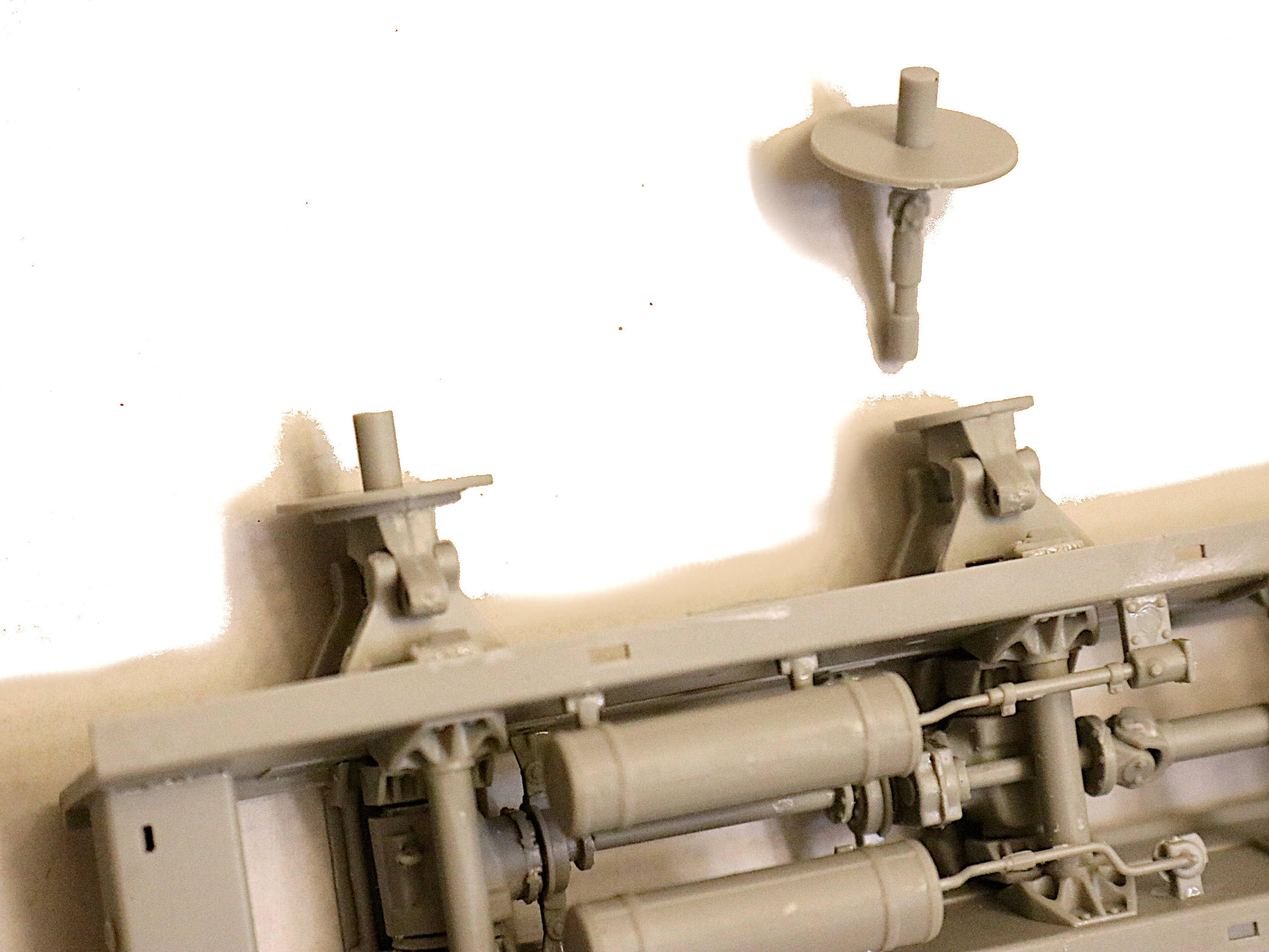
ASSEMBLY NOTE: You are going to want to round off the ends of those axle shafts just a bit. This to make it easier to insert them into the poly-caps contained in the wheel hubs. If left as-is they will require so much force as to almost break the suspension while trying to get the wheels on.
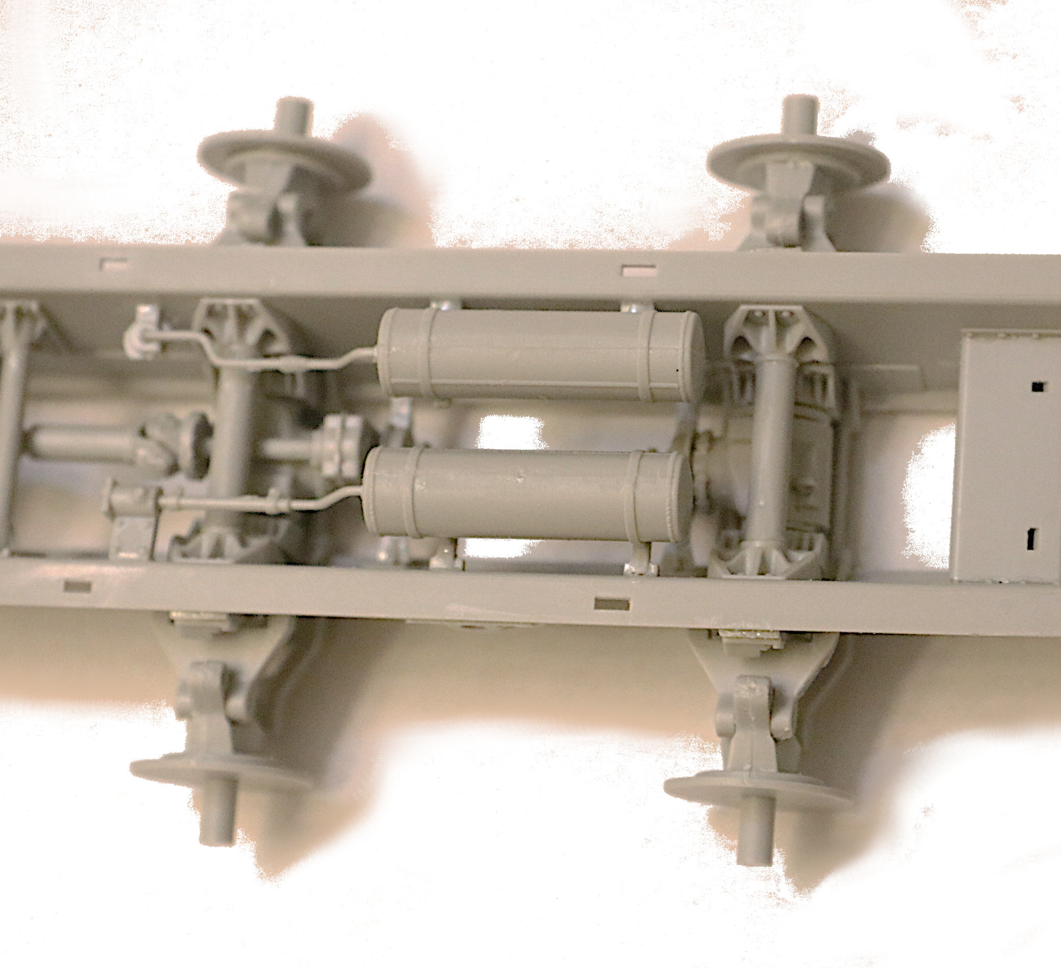
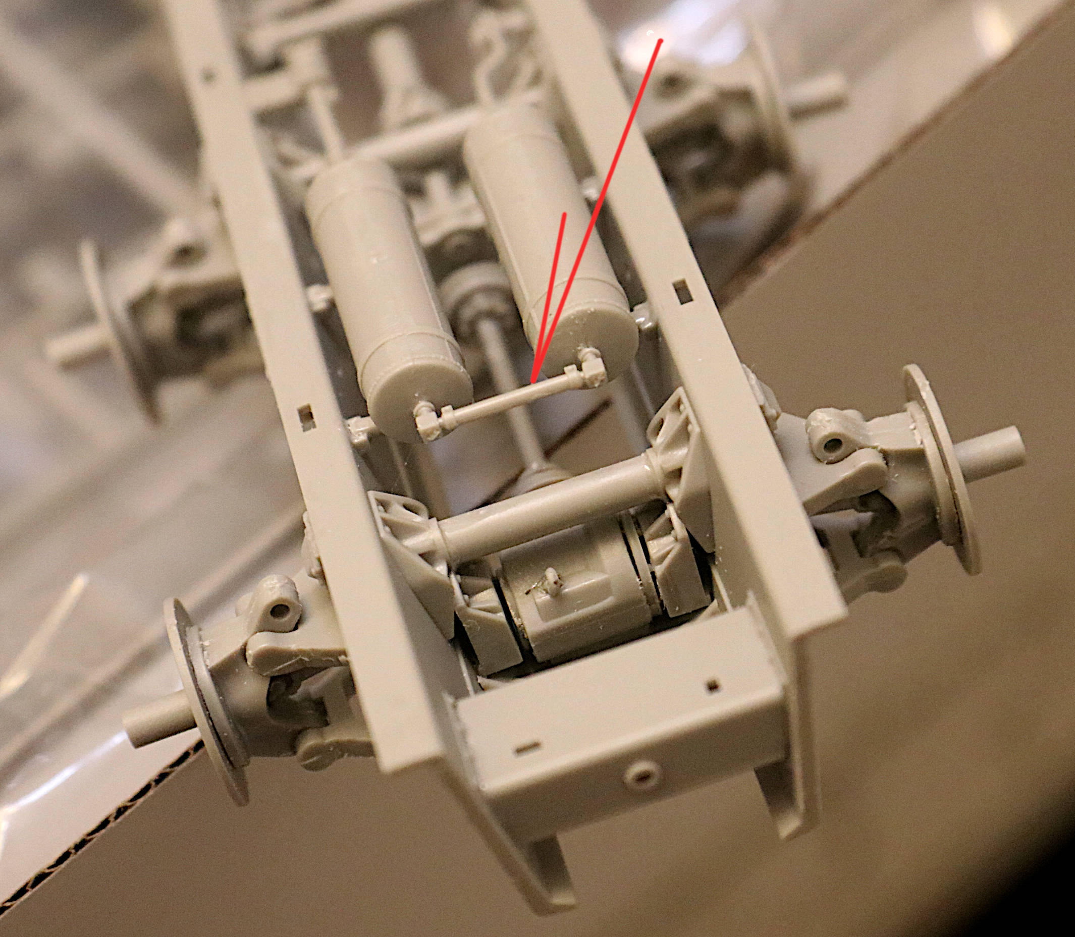
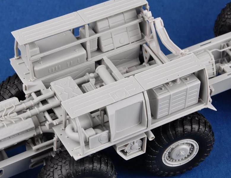
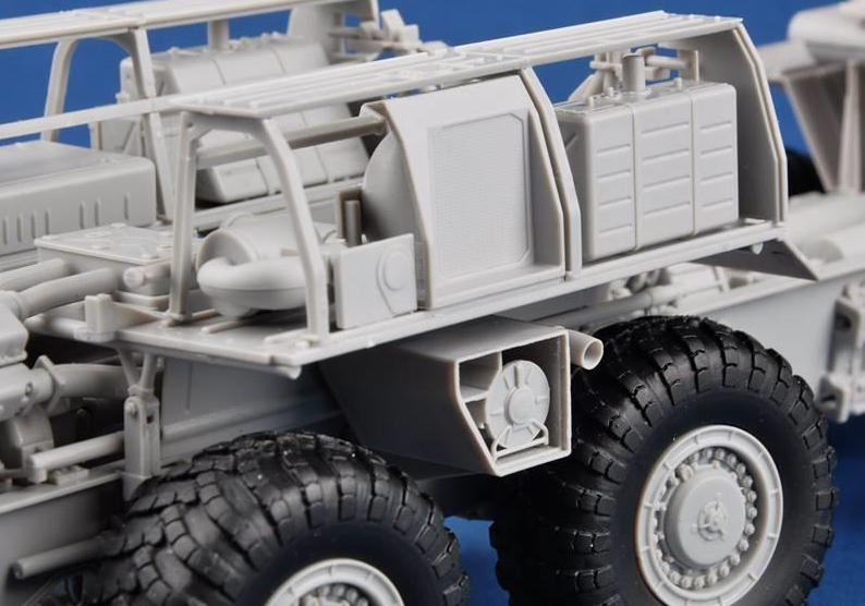
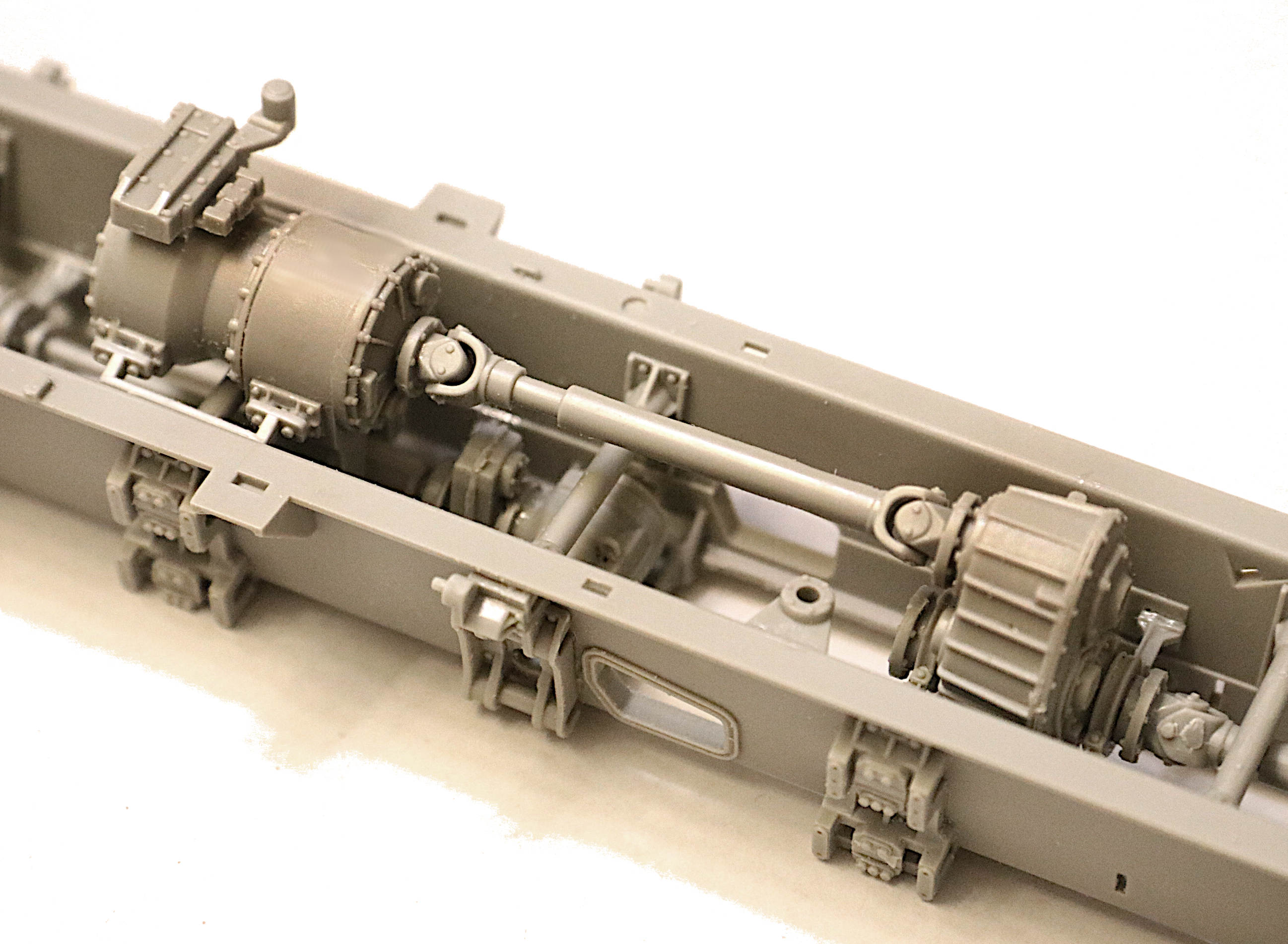
Also - personally, I would suggest leaving these two very nice air tanks and their associated plumbing OFF the chassis assembly until much later in the process - or at least until the suspension is complete, they are very much subject to getting bent down or broken during the later assembly steps.
They will still be easy enough to install later on in the process.
When you do decide to install those two beautiful air tanks on the chassis you might want to track down part #P51(easy enough to remember) as this little pipe will do much to align and support the two tanks and keep them properly spaced. As it is the instructions don’t have you installing this item until MUCH later in step 10!
Stryker45 ~ I am pleased to report that the latest Scud B kit from Trumpeter appears to utilize the same highly detailed chassis as you are seeing in my thread here.
Here is a link to an “In-box video review” of that kit and at about 6:12 into it the fellow shows us the early pages of the instruction manual and the drive components appear very similar to those I am dealing with here.!
Building one of these MAZ trucks is like having to build one seriously nice model kit as penance BEFORE you get to start building the kit model you actually thought you had purchased.
In my case it is just the opposite - as I love the chassis work - once I finish that GREAT chassis I often loose interest in the fancy sheet metal you cover it with. (This is my fifth with another possibly waiting in the wings!)
You may have noted that I so far left off the forward driveshafts from in front of the transfer case on my current build. I suspect that something is missing. I suspect that Trumpeter has decided to delete the parking brake assembly to reduce kit production costs. Now it may be that MAZ has changed the basic design but every 537, 534 and 7410 chassis I have even seen has had an E-brake assembly.
So all I can say is my 7410 is going to have one also! I’ve built them before, I can do it again.
Based on the instructions viewable at Hobby Search, all of the 537 based vehicles appear to have the old, simplified transfer case and all of the 543 based vehicles have the newer transfer case.
Question, is the rest of the drive line behind the transfer case the same on both the 537 and the 543?
Keep building, Michael as I have much more I need to learn from your builds!
John
As far as I’ve been able to tell the driveline components for the 537 / 543 & 7410 (the REAL trucks) are all similar/identical. With the only differences being the axle spacing and general engine layout.
The driveline components of the older 537 (Trumpeter model) are, to my view, absolutely atrocious. Trumpeter now has all the necessary tooling to properly detail and reissue that earlier model and yet so far nothing???
If you want to build a really good 537 model you would have to buy that model and then special order all the driveline sprues from one of these newer issue model trucks and combine the two - which would then be relatively easy.
p.s. Get the steering sprues as well because there are none offered on the old 537 kit. Oh, and the main frame members are better detailed than in the old kit.
Oh heck with it ~ just buy BOTH models in order to build one! That will make Trumpeter REALLY happy!
I don’t plan on NEEDING to build a lot of extra detail into this truck as it looks very well done so far. ~ (Other than the missing E-brake and winch.)
Adding the winch will mean I do have to build the PTO take-off for the top of the transfer case to power that winch and also add a small drive shaft to connect the two.
Beyond that I see me only needing to add some signal cabling and hose lines to the chassis.
Just another general modeling gripe/comment . . . .
Model manufacturers these days will often go to great difficulty (and expense) of making a totally separate sprue, using 3-part slide mold technology, just to create the MAZ exhaust pipes that will then have open holes in the ends of the pipes. (As Trumpeter has done on this kit.) And yet they will leave out the E-brake to save on tooling costs???
I am easily capable of drilling open holes in the ends of the old fashioned style model exhaust pipes but it is another matter entirely for me to have to scratch build items that the manufacture has left out of the kit and not told us about.
Building a modern plastic kit these days is much like playing a mystery “who-done-it” game like CLUE.
Hummmm . . . Now let’s see what mysterious surprise part did they leave out of this kit thinking “no one will notice?”
“Was it Colonel Mustard in the Kitchen with the Clever, or the E-brake on the Transfer Case in the Driveline? . . . .”
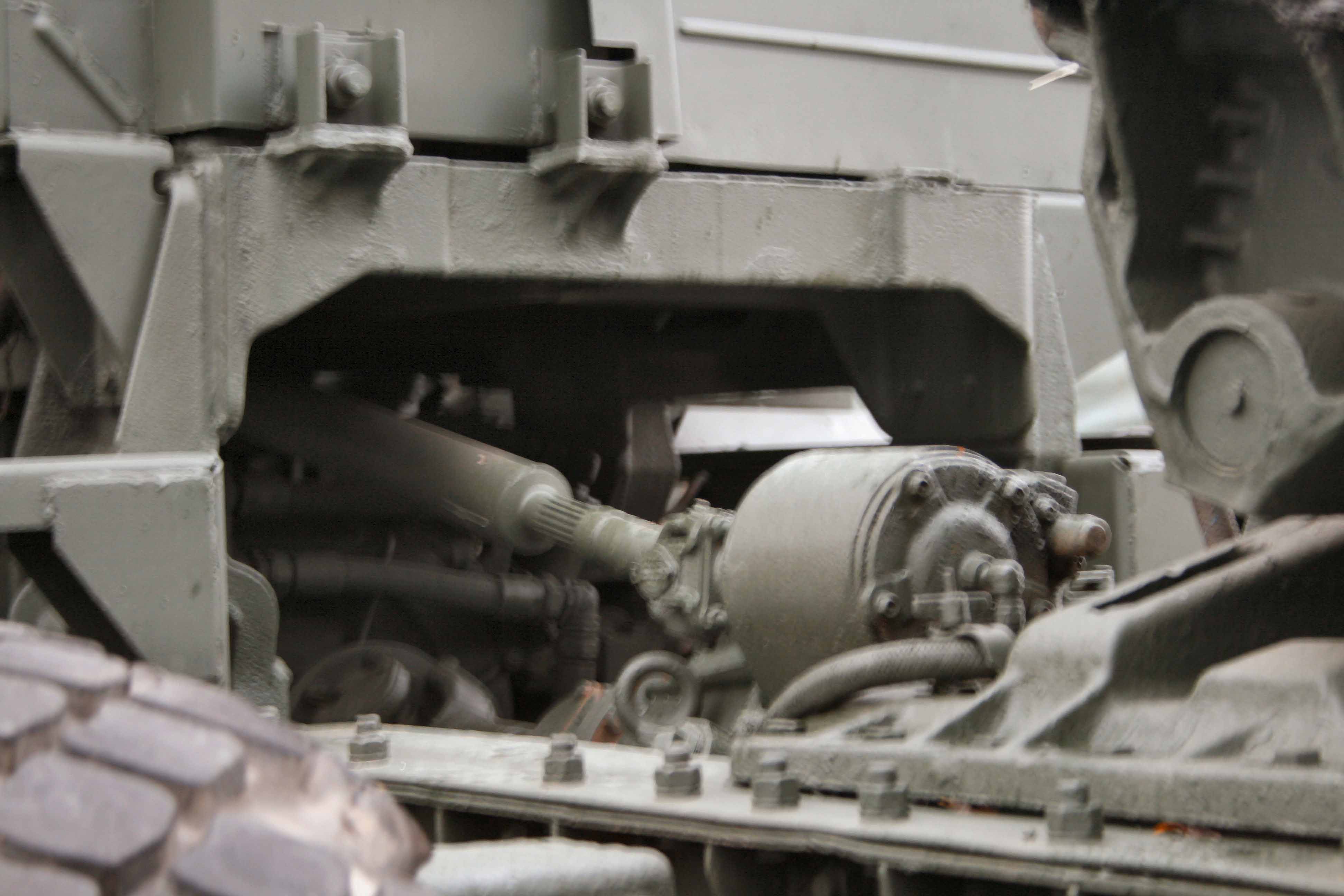
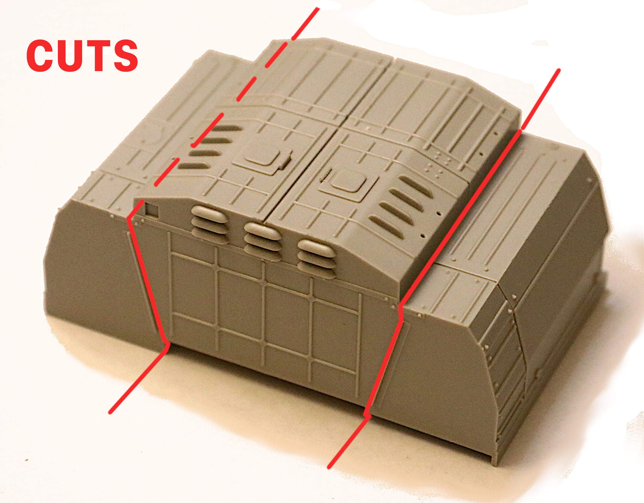
If I could I would cut those “side attic” areas open and fully detail them as in the real truck video I posted several steps back above.
I just found an “Unboxing Video” of the Trumpeter Scud TEL and these side sponsons are FULLY detailed out in THAT kit, even though they will all be covered up once the Scud sheet metal is in place???
Unfortunately Trumpeter divides their sprues more by “what we will need four of, or what we will need eight of” rather than by sub-assembly or subject. (I can’t really blame them for that from a production stand point.) But it does make it difficult to order just the sprues one needs for a certain area of the model because the parts seem to be scattered all over the sprue layout between many multiple sprues.
Aah . . . to be living in the digital age even as it relates to automated computerized parts / sprue layout and how the sprues are divided up.
Getting back to those twin air tanks again . . . .
When you do decide to install those two beautiful air tanks on the chassis you might want to track down part #P51(easy enough to remember) as this little pipe will do much to align and support the two tanks and keep them properly spaced. As it is the instructions don’t have you installing this little item until much, MUCH later!
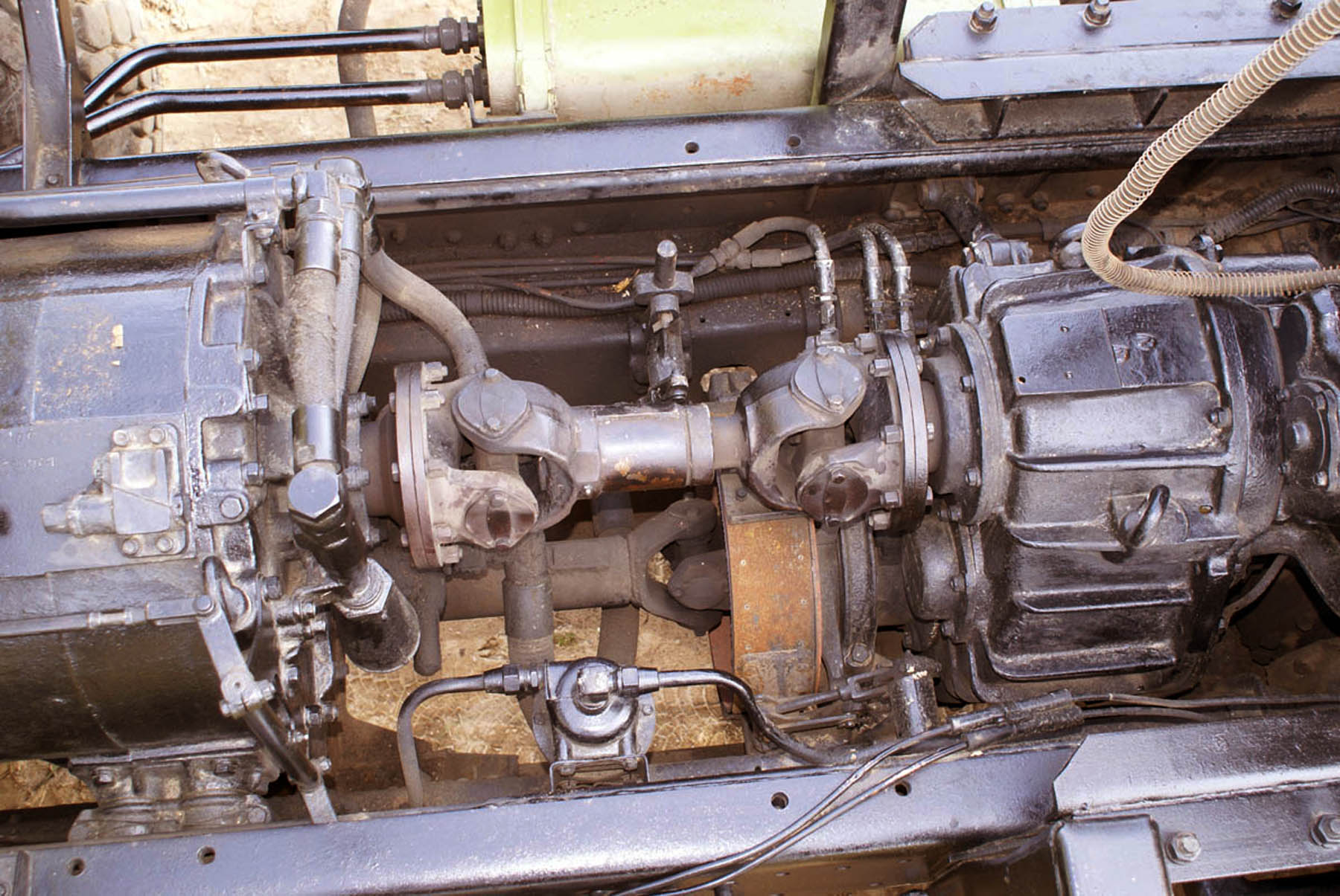
This will already be common knowledge to many but . . . You should never install your driveshafts with the U-joints straight up and square in either the 12,3,6 or 9 o’clock positions. Install them erratically on purpose. A driveshaft rarely comes to a stop in exactly the “straight up” position. Rotate each one to a slightly different angle when building your model.
Also if a vehicle has many driveshafts such as the MAZ here, the shafts WILL NOT ALL be at exactly the same angle of rotation. (Unless perhaps they were assembled at the factory, all at the same time, by a very anal retentive or, an extremely OCD afflicted mechanic. - no offense intended to those who suffer with this!)
Anyone care to part with these items out of your Trumpeter Scud kit? I will pay handsomely for same! + Shipping. (I only want/need just the internal mechanical parts that will not show anyway if you choose to close up the body sheet metal in these areas.)
I am already planning on cutting that large “attic roof molding” into three parts so that at some future date I might be opening it up to install these missing items.
Does anyone else ever have the need to switch to building some other, easier task in a large kit just to take a little break from the S-B-S instructions???
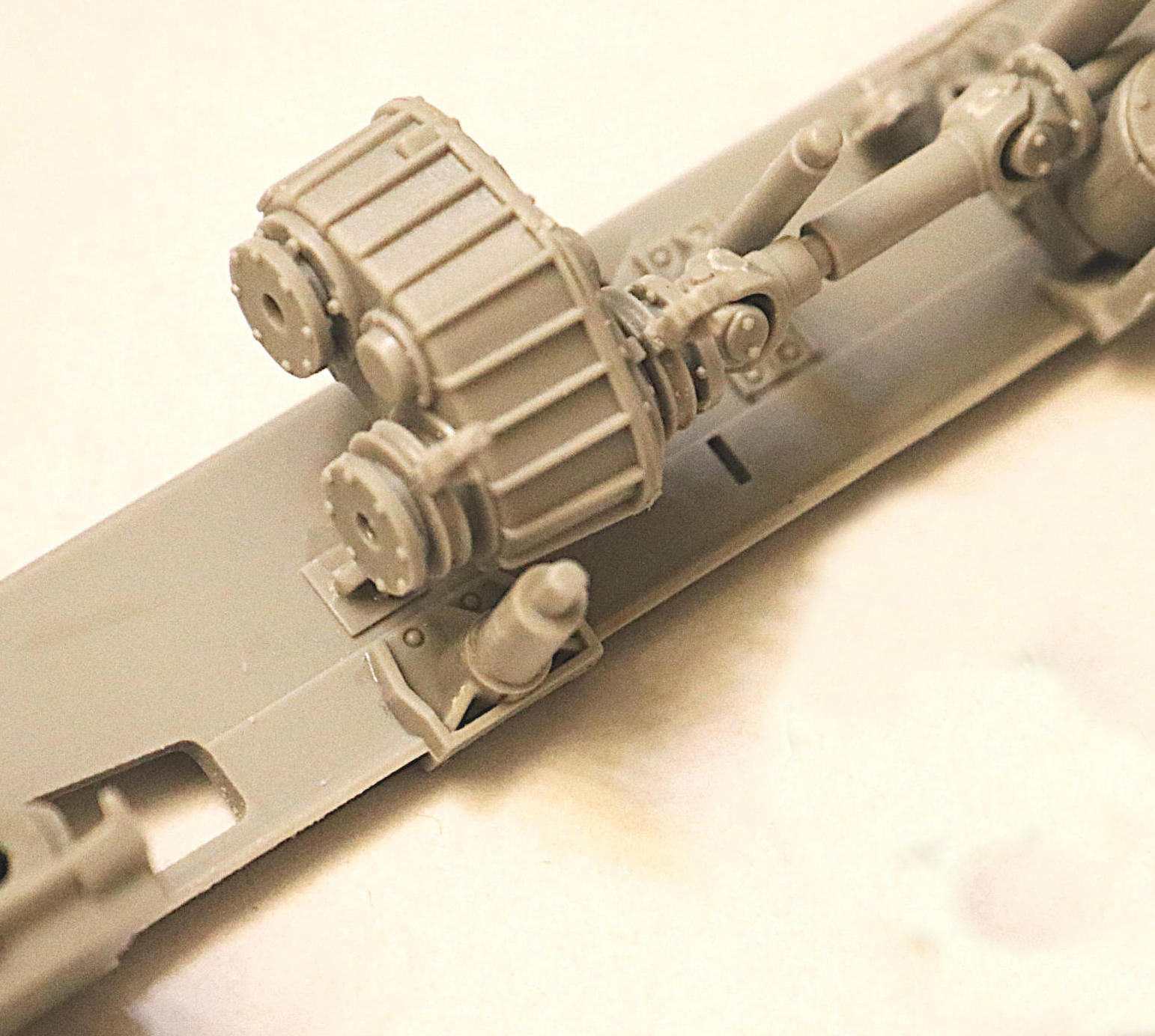
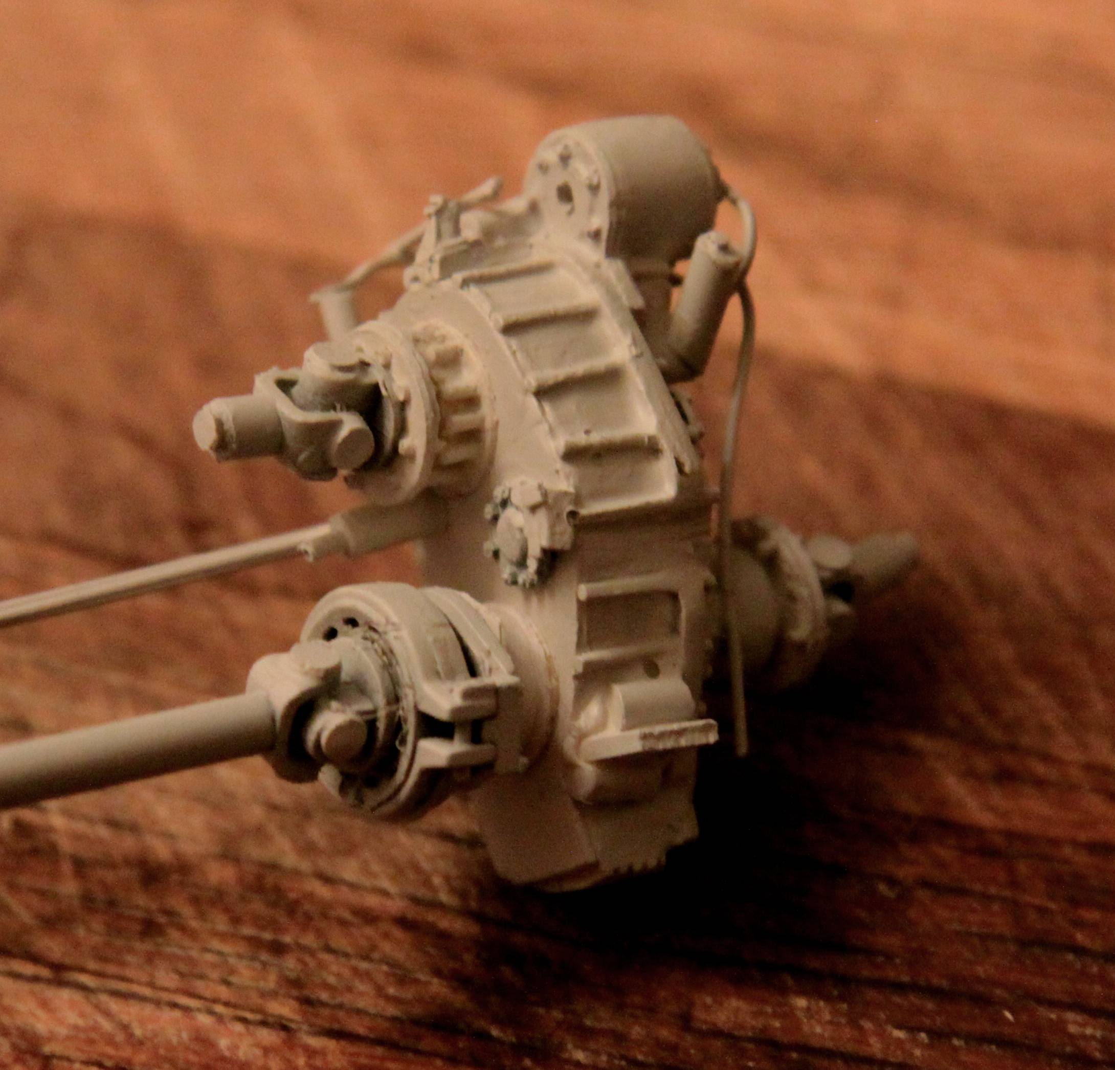
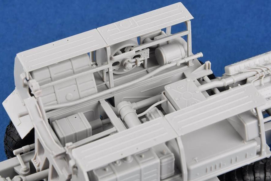
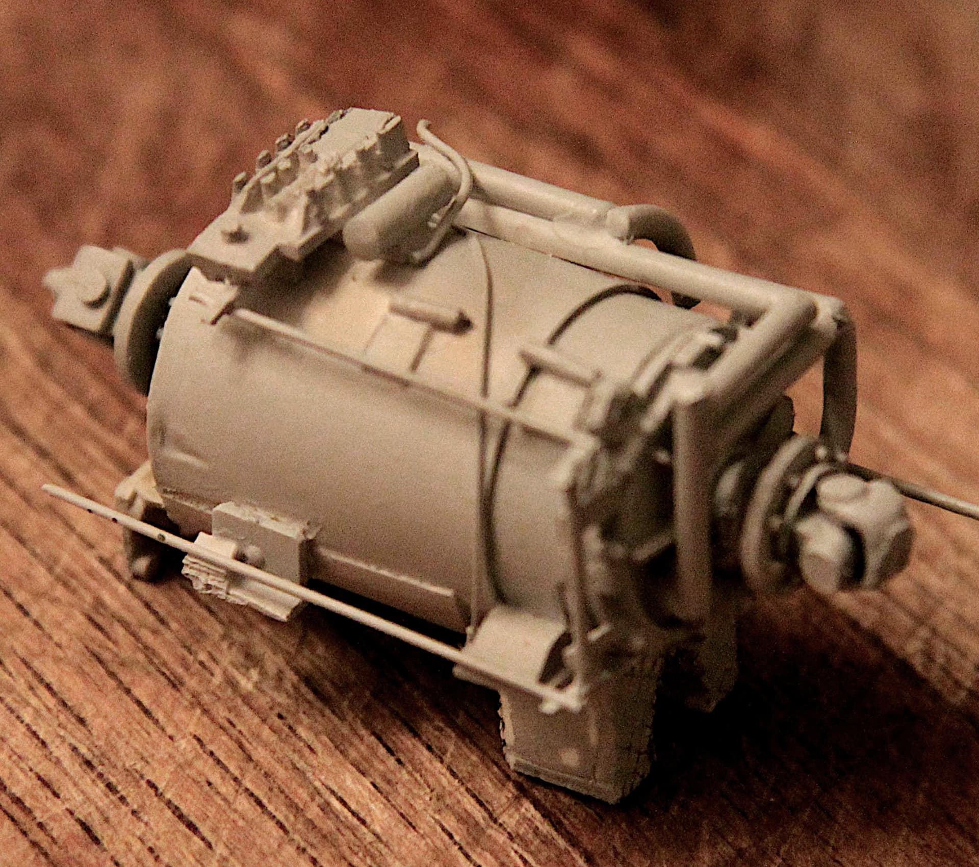
I had to take just such a detour, so I moved over to something simple: the transmission.
Note of Caution: those two side mounting brackets have keyed notches in them which are supposed to face downward. However the instructions do not specifically call this out with any sort of warning or instruction and they can easily be installed incorrectly…
Those two “legs” coming out of the bottom of the tranny - those form a split oil sump. (Split because a driveshaft runs between the legs.) They are supposed to have a raised crosshatched pattern on them. These raised ridges act as cooling fins to help radiate heat from the oil. On my earlier scratch build I used plastic model screening laid at a 45 degree angle to simulate this “XXX” textured surface.
That blockish shape on top of the tranny is the “fluid logic module” - (a fluid based computer if you will) it would contain a series of fluid pressure sensors and if/and/then logic gates (fluid relays) similar to those that serve to control all modern automatic transmissions. Parker Seal here in Lexington has a division that focuses on what they call “Fluid Logic Applications”. Some of their robotics have very similar looking fluid logic control blocks.