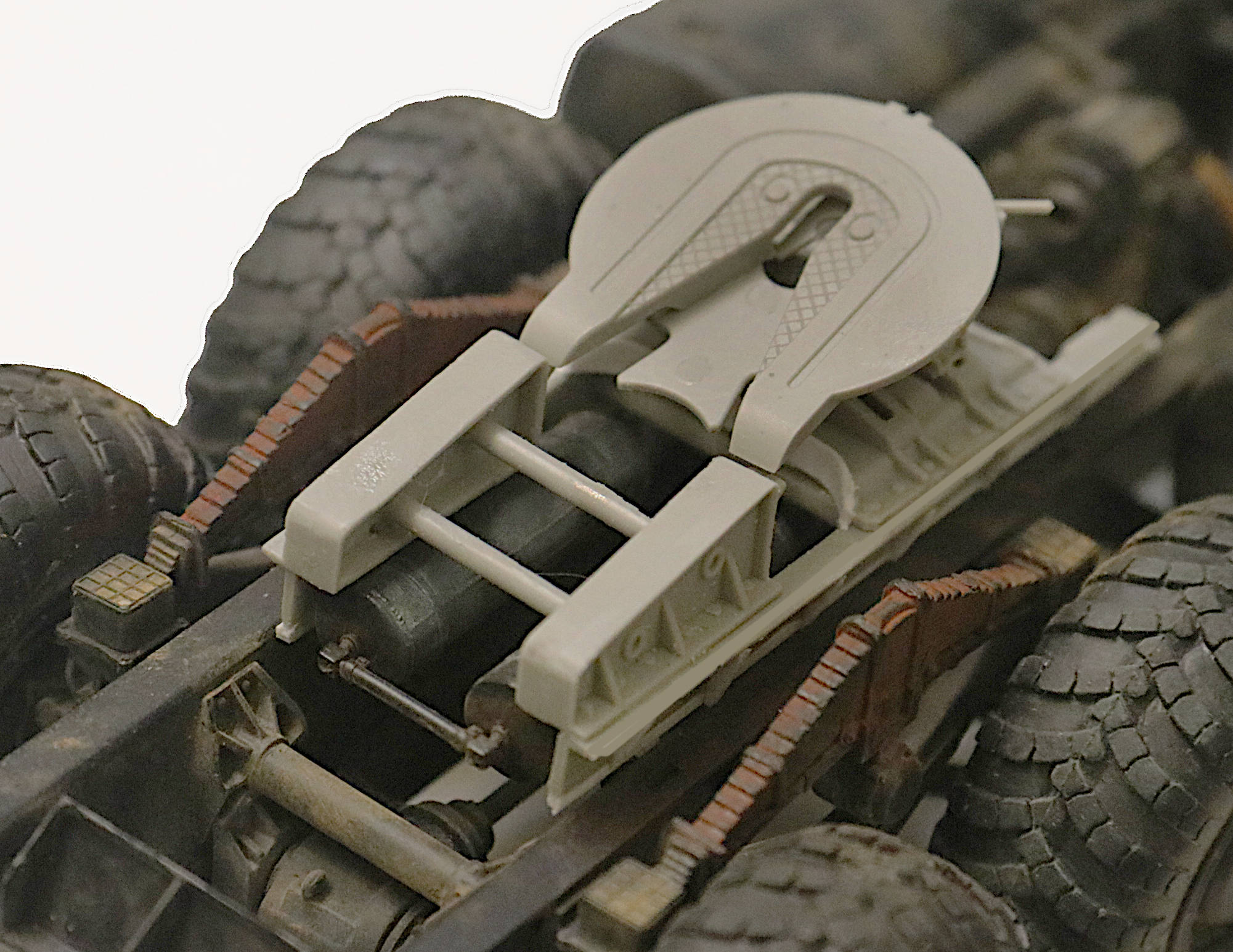
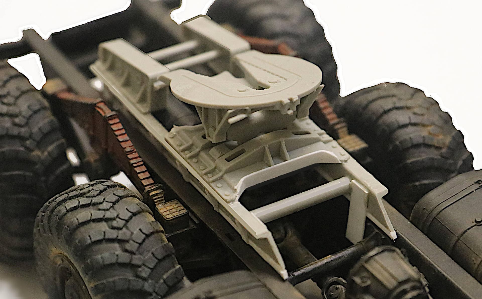
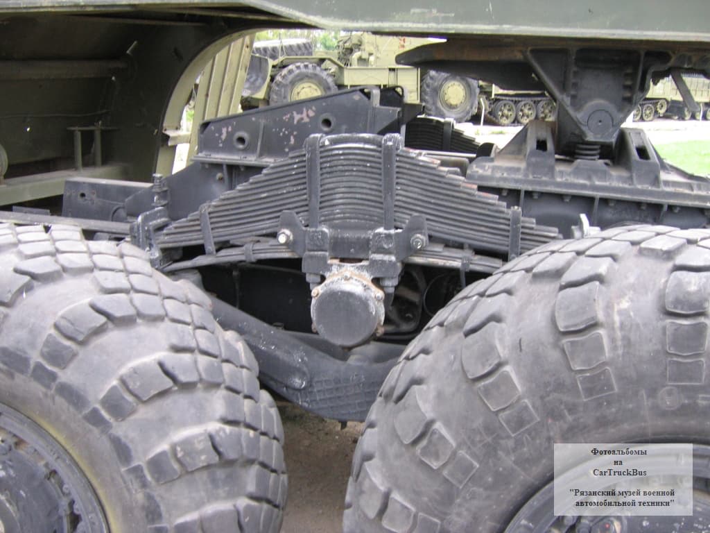
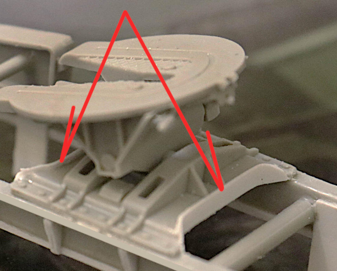
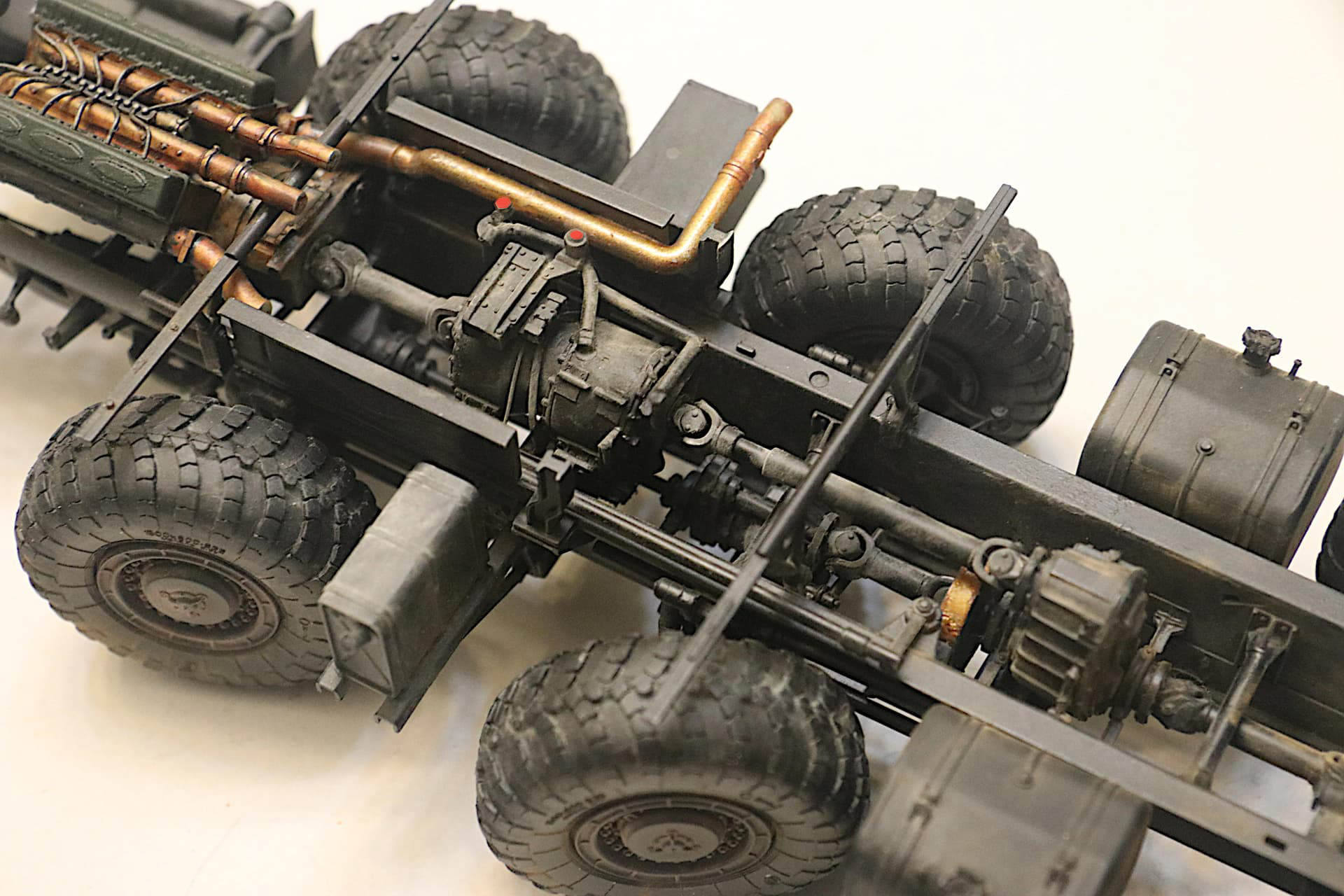
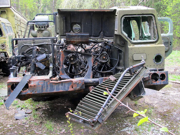
On this bottom photo the flange on the sub-frame faces inward. (More like Trumpeter has portrayed it in the model.) So clearly there must be several variations in the actual, real life, design. My main concern was that Trumpeter’s solution still has the run-up ramps much too widely spaced compared to the fifth wheel.
Looks like a good solution. Add the rivets .
Added this missing flange detail to the fifth wheel baseplate, fore and aft - easy enough with just a little Evergreen.
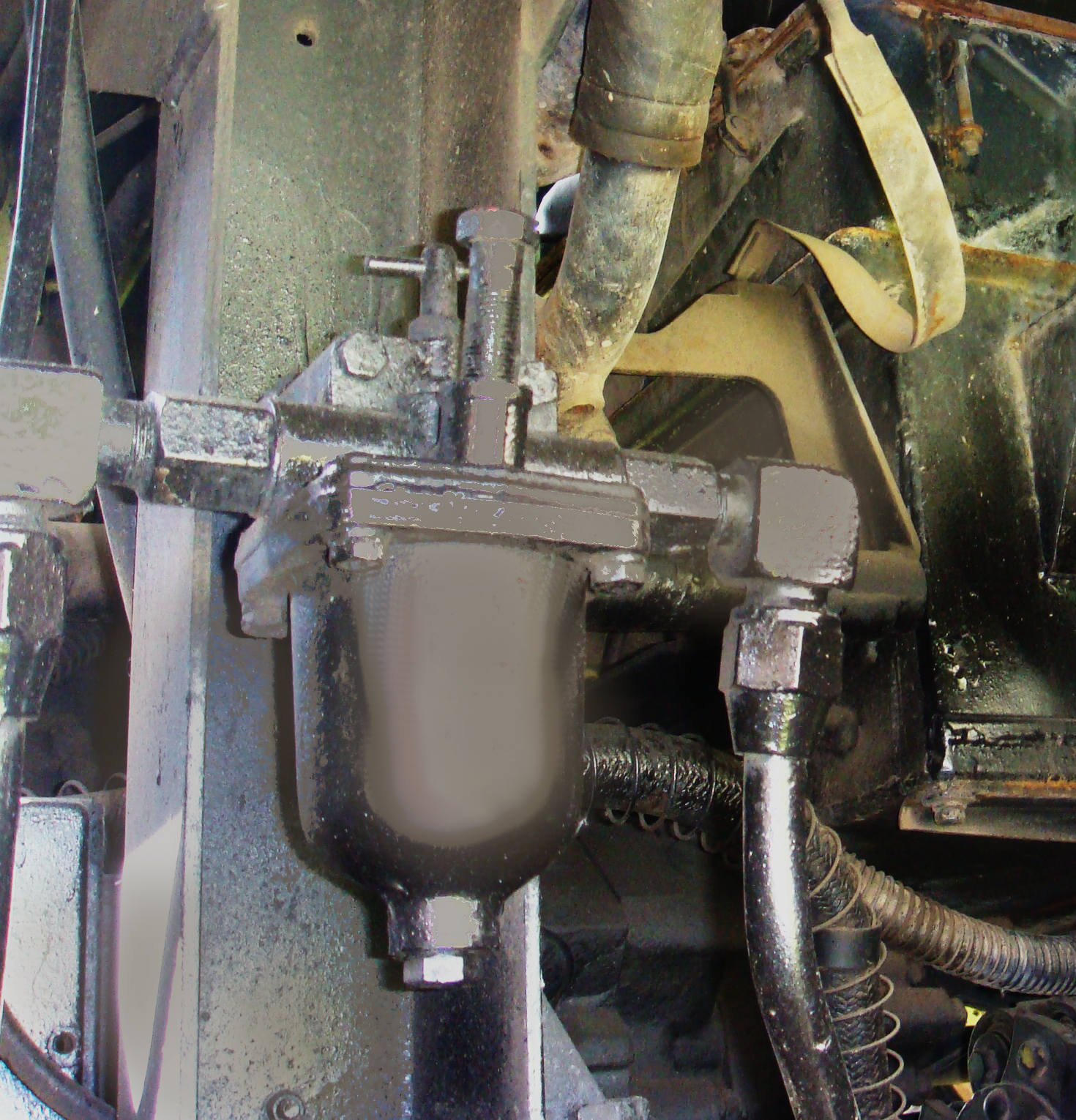
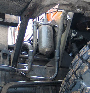
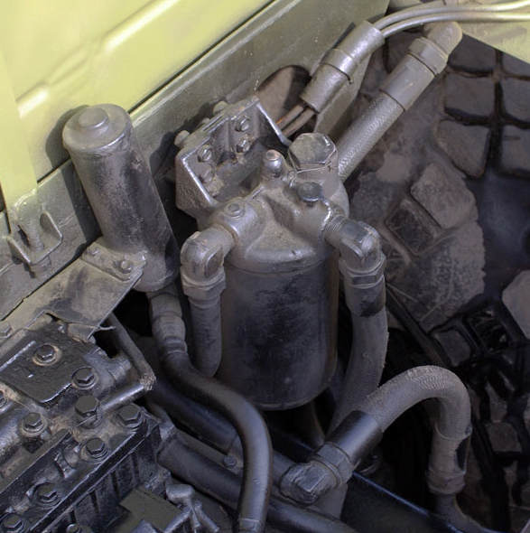
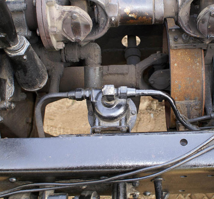
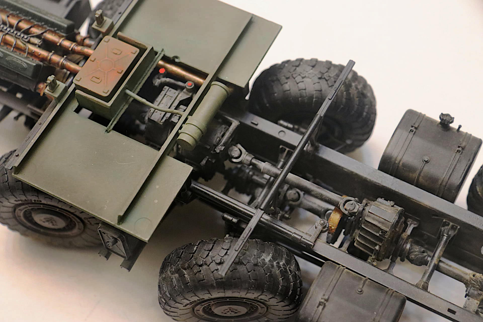
More than a few cup shaped oil filters seen on all these big MAZ 8x8’s:
Perhaps a somewhat minor detail but they can certainly add to the overall complex appearance of this great Trumpeter model. (Sorry my photography of these small items is so poor - I am working on improving this!)
Transmission oil filter.
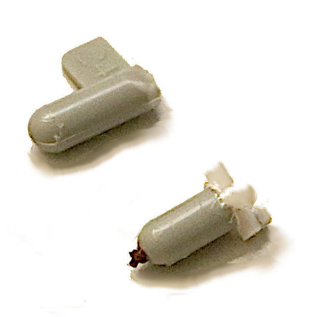
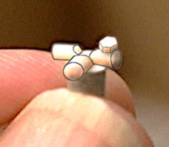
Interestingly there seems to be a large number of blunt end, rounded sprues spread around the sprue parts layout on this kit. Perfect for cutting off to make these rounded end, cup shaped oil and fluid filters.
Start by cutting off the round ended piece of sprue and remove any mold lines + sand the top of the “filter” flat + add a slightly oversized disk of thin sheet plastic to represent the upper screw top of the cup filter + use a bolt casting for the bottom drain + then small lengths of rod for the various upper pipe fittings + and finally a short length of hexagonal rod - if required - to form the filler cap on top. (I usually paint these hex caps red or yellow just for additional visual interest.)
Often there is some sort of mounting bracket included and so a short length of Evergreen “C” channel will work for this.
Oh that is super nice . great detail
Apologies to all - I have had to take a Holiday break on this build but more significantly I had some oral surgery scheduled just yesterday that is unfortunately focusing my attentions elsewhere right now. - it was NOT fun!
No problemo Mike ! (Un)fortunately, we all have a life outside the Internet…
H.P.
Some great building going on with this and some wonderful ref pics of the variants and different big 8 wheelers …

Man Mike you’ve taken another Maz truck and transformed it into a fantastic build . I have the Bereg in the stash, and have been eyeing the Panzershop crane conversion for a civilian theme truck
Keep up the epic work
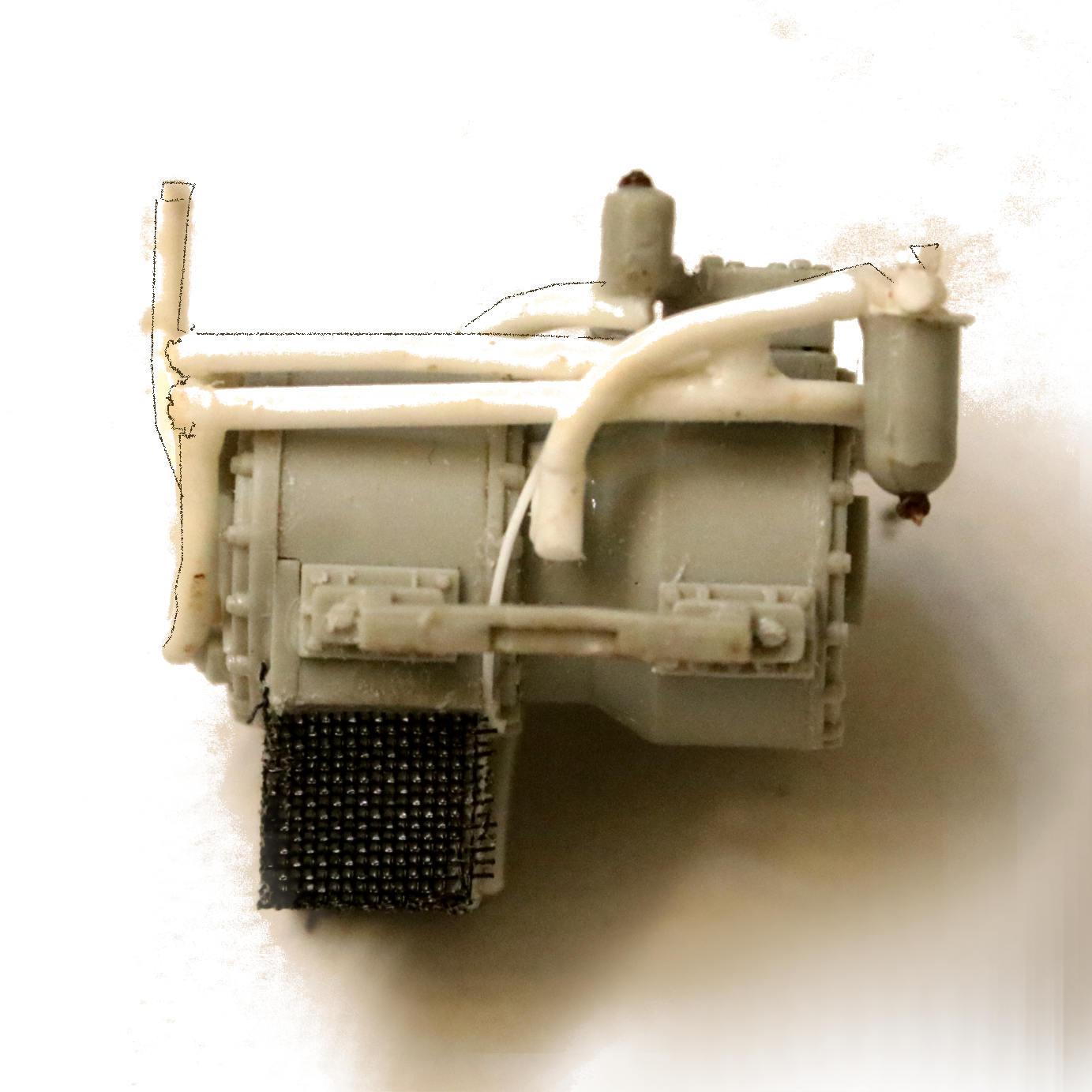
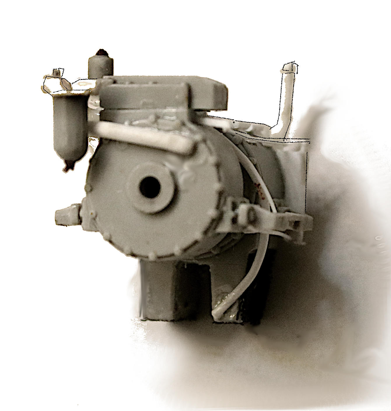
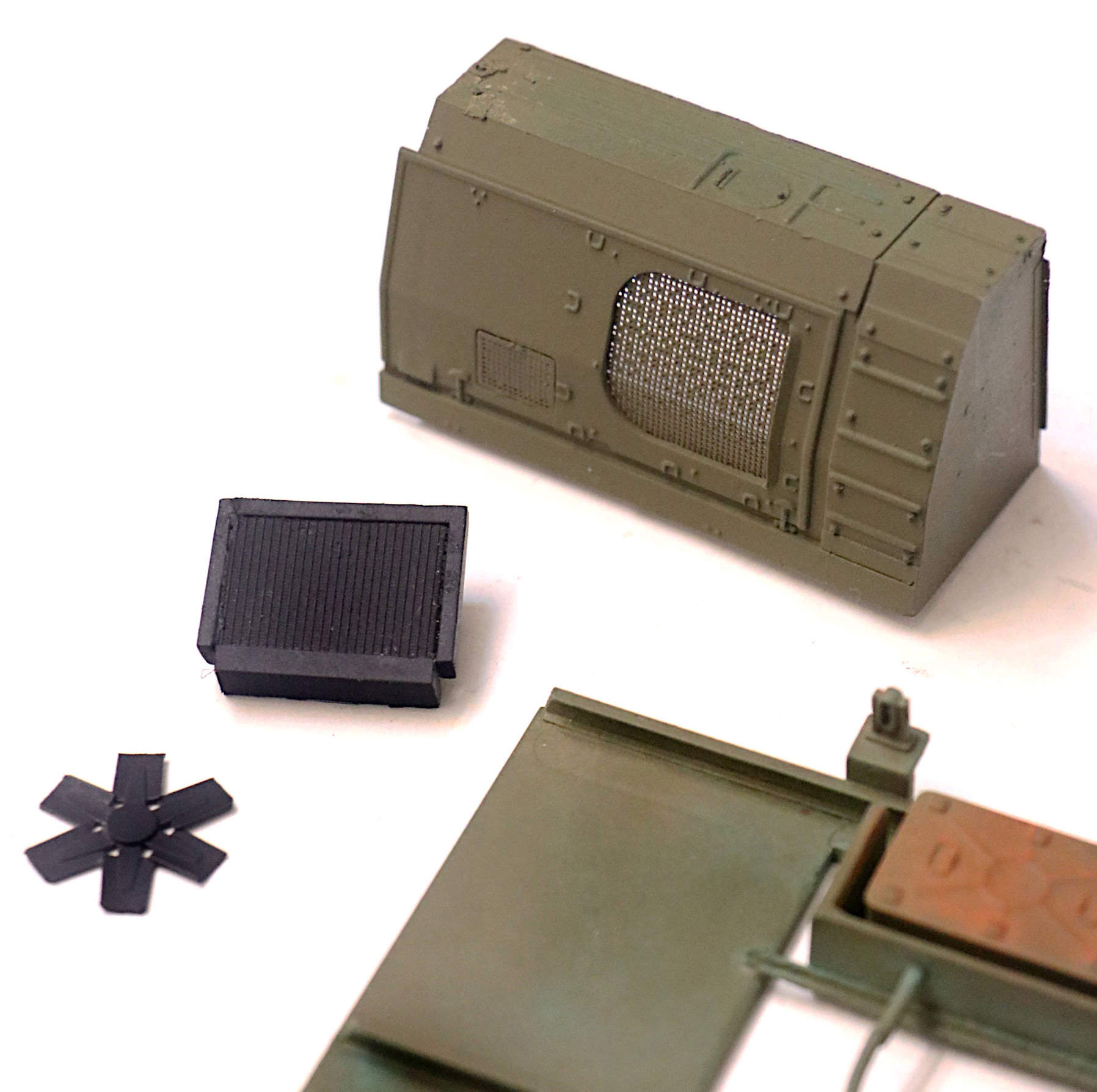
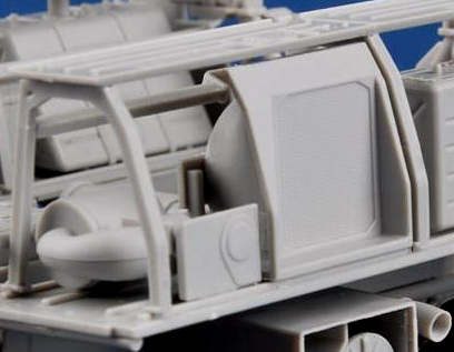
Transmission Oil Cooler:
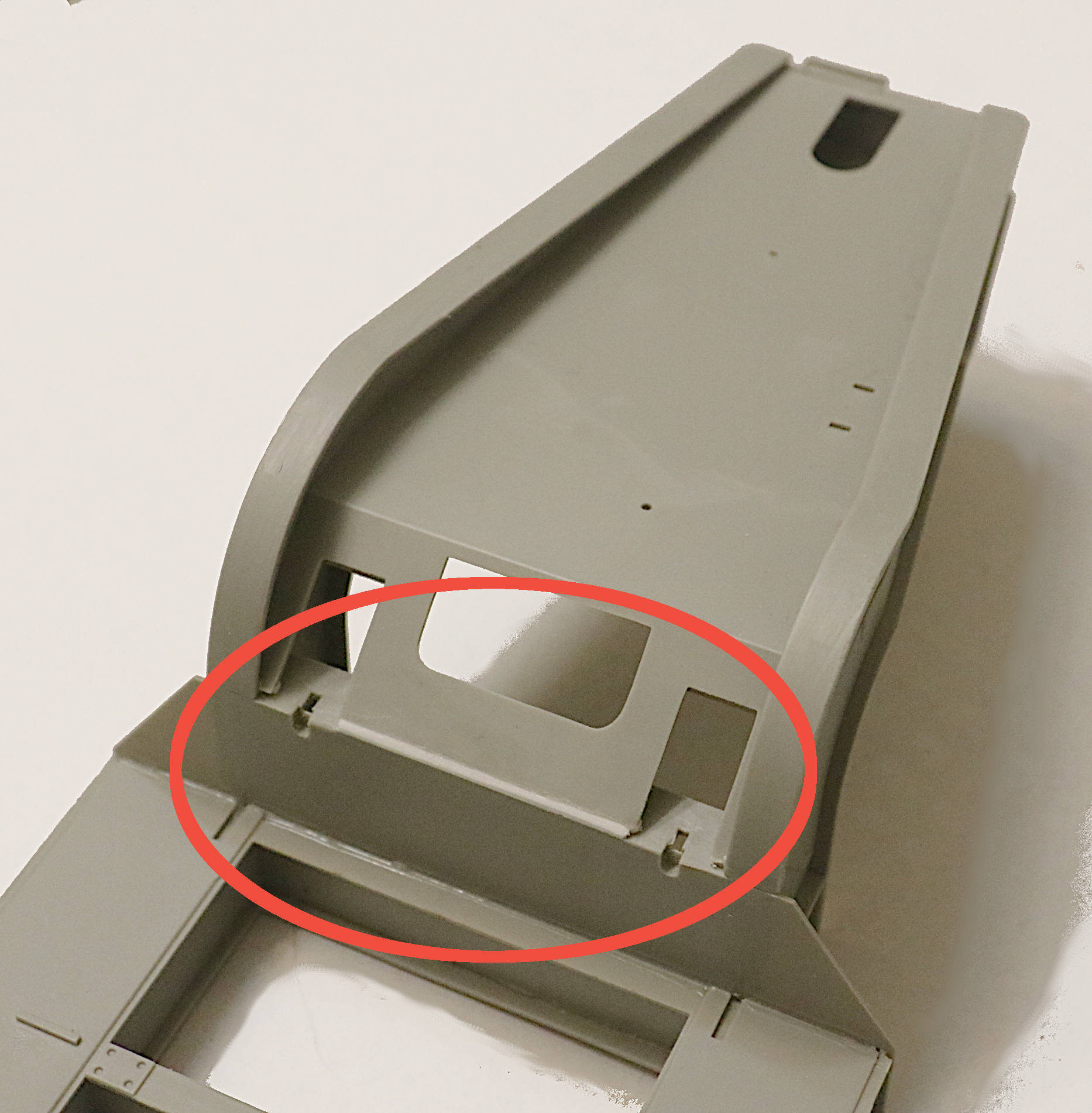
Oil Radiator and Fan assembly to mount behind the driver’s side screened opening in the “attic” behind the cab.
 . .
. .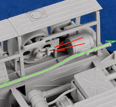
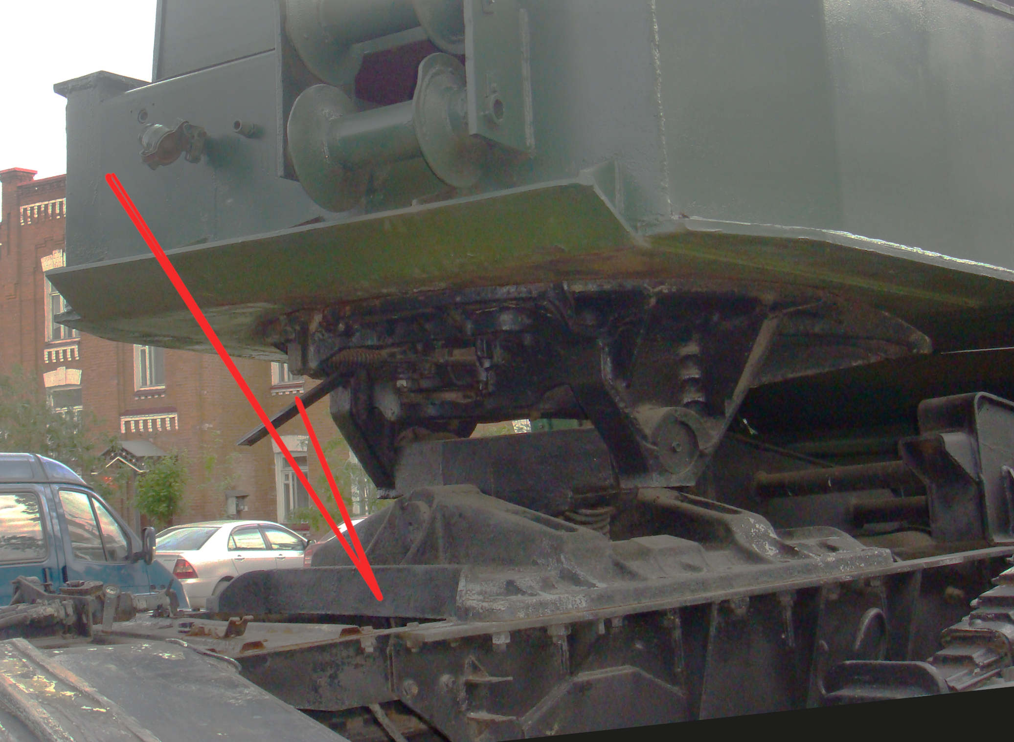
Details seen above are from the even more detailed MA3 Scud kit. I have seen this fan as being either hydraulically driven (hoses) or with a small drive shaft and gearbox off the rear of the engine just as the air compressor.
In the right-hand photo above there appears to be twin hose connections going forward there.(Red Arrows)*
That topside access hatch on the outside body must cover the filler cap for the oil radiator (cooler).
QUESTION: Does anyone know just what that air filter assembly just forward of the oil cooler is intended to be? I thought perhaps a Nuclear/Biologic air filter for the cabin air??? It is present on most all the big MAZ trucks. The SMERCH has the same filter as well.
___________________
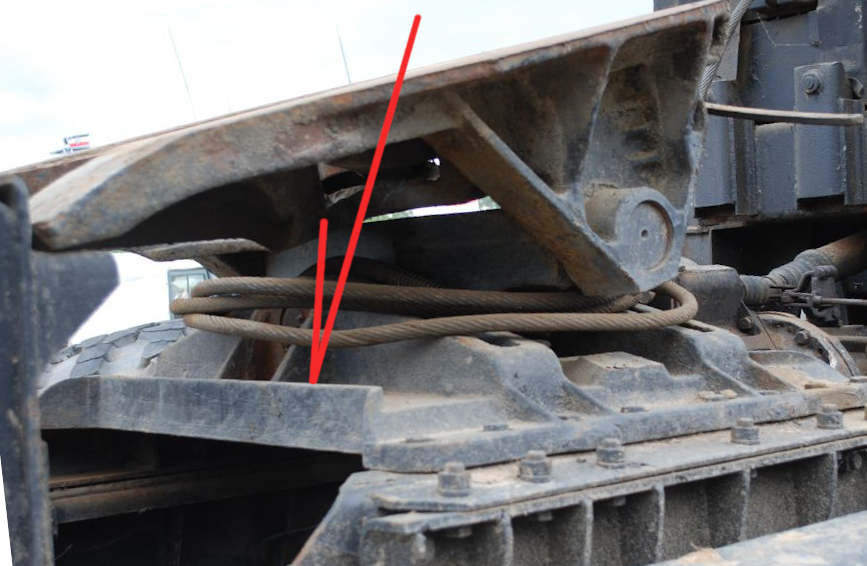
Here is a wrecked single cab MA3 truck and you can see the oil cooler and air filter assemblies have now been moved to the front right corner of the vehicle.
Wrecks can be reference!
I think you’re right about it being the NBC filter canister, a similar looking canister & ductwork is present directly to the right rear of the turret on T-64 , 72, & 80 series tanks.
Thank you Sean, I did not know that.
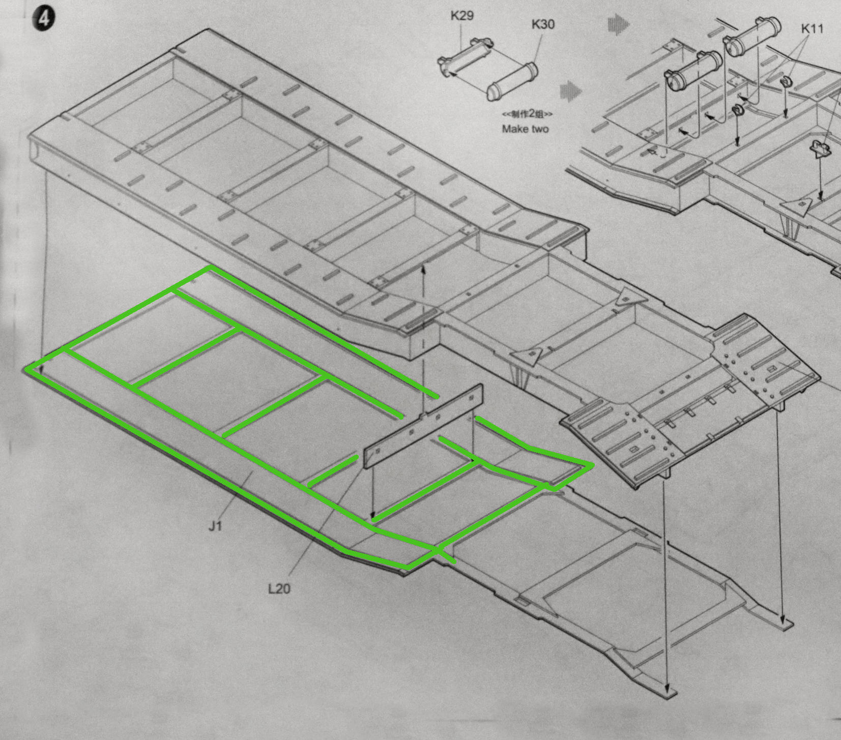
In the photo of the Scud model above you can also see a feed pipe (Green Line) going forward to the driver’s cabs and also running to the rear to serve the command/control compartments.
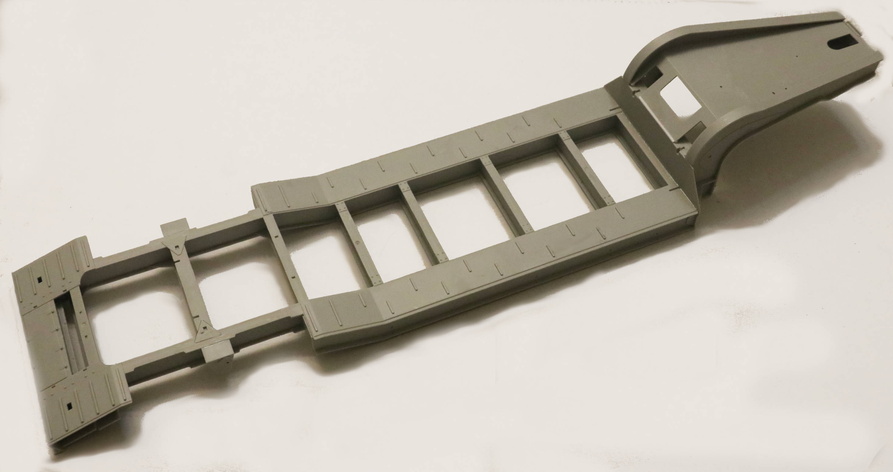
Started some serious assembly work on that big honk’n trailer.
. .
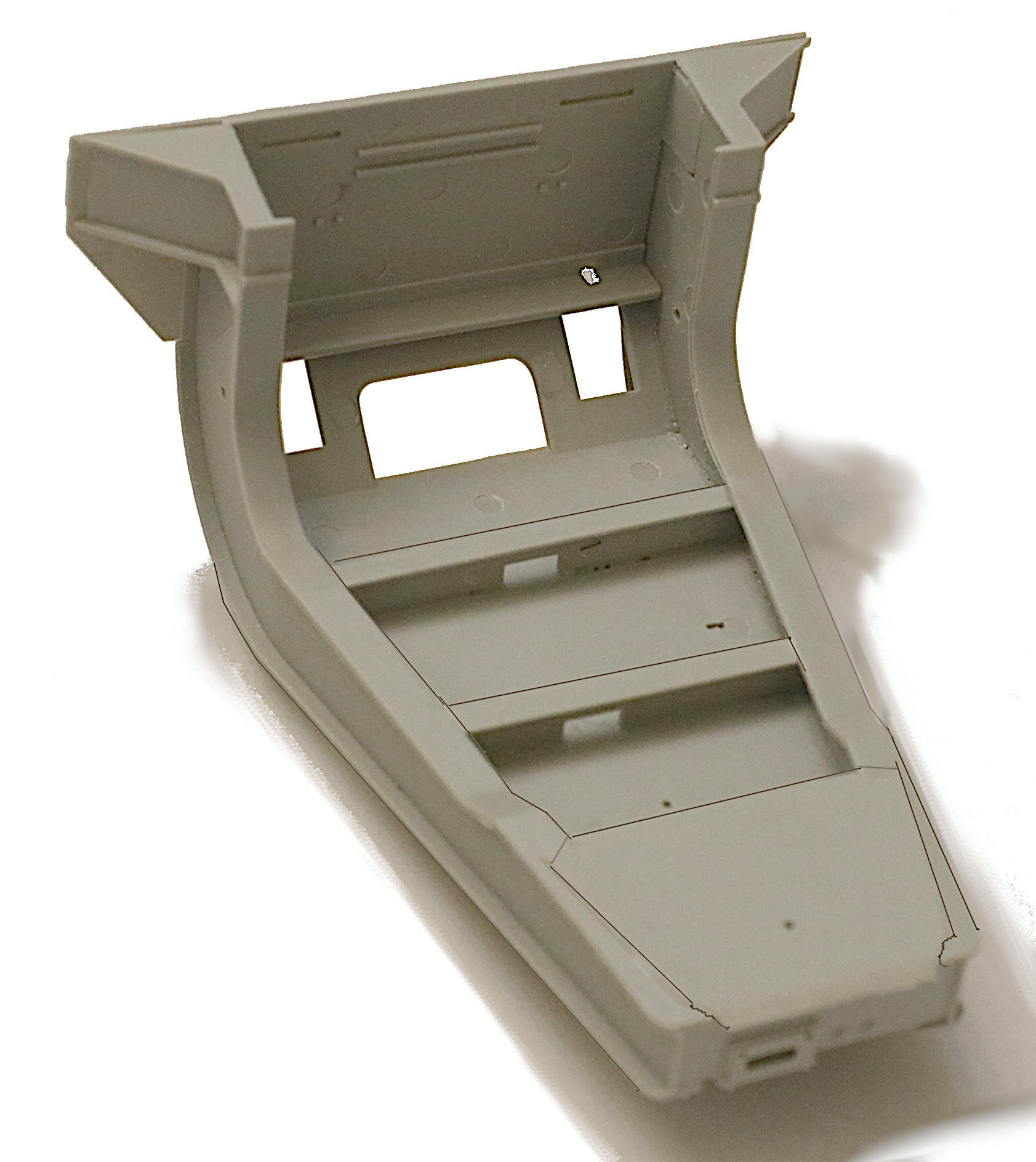
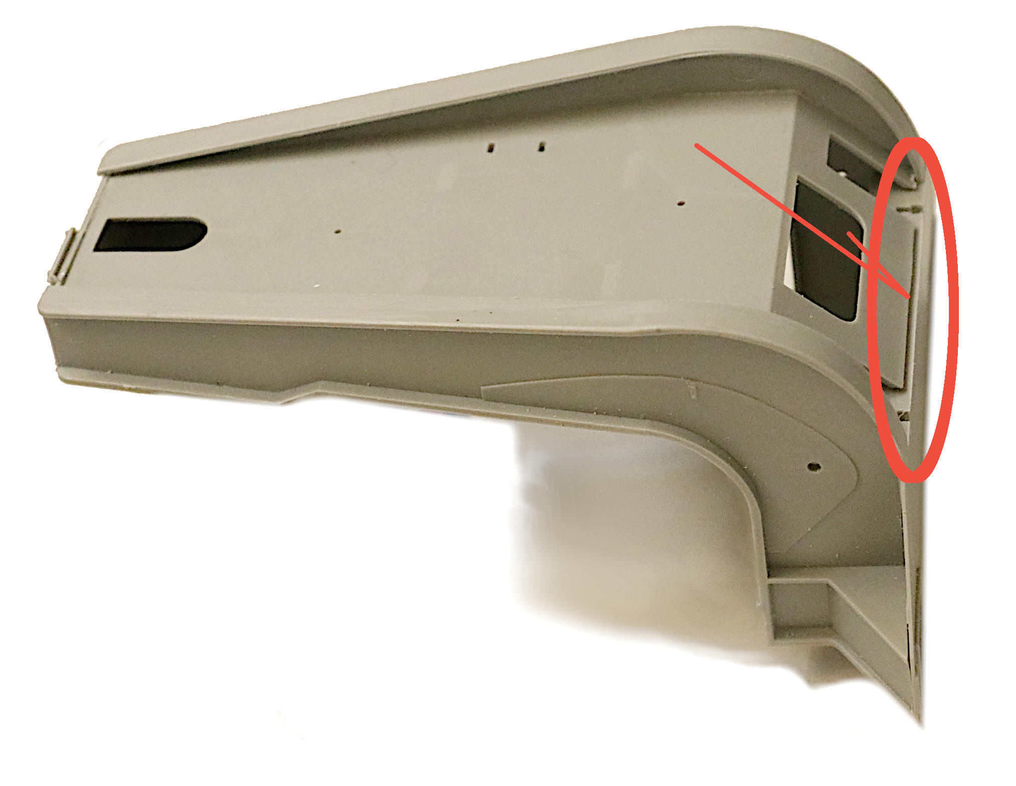
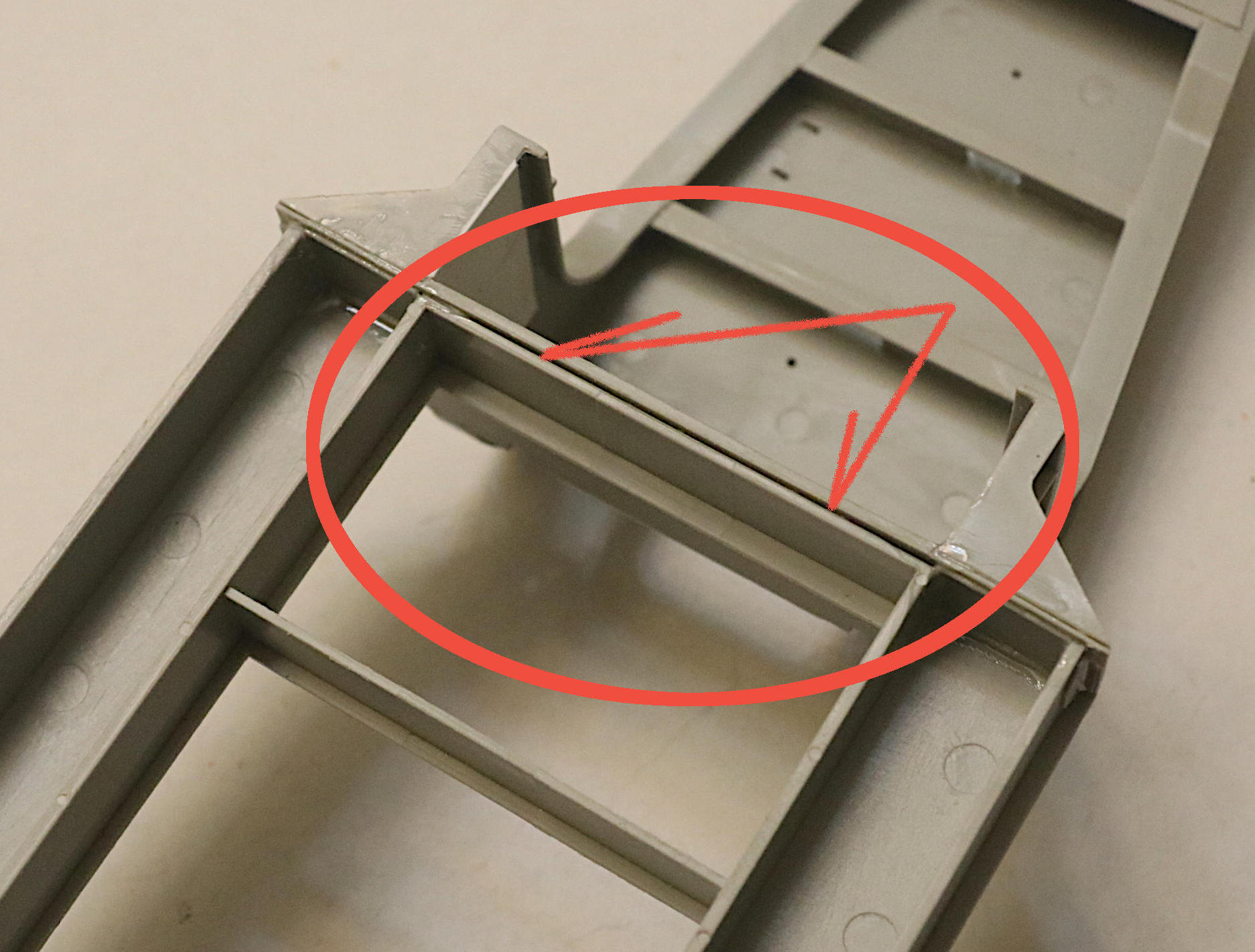
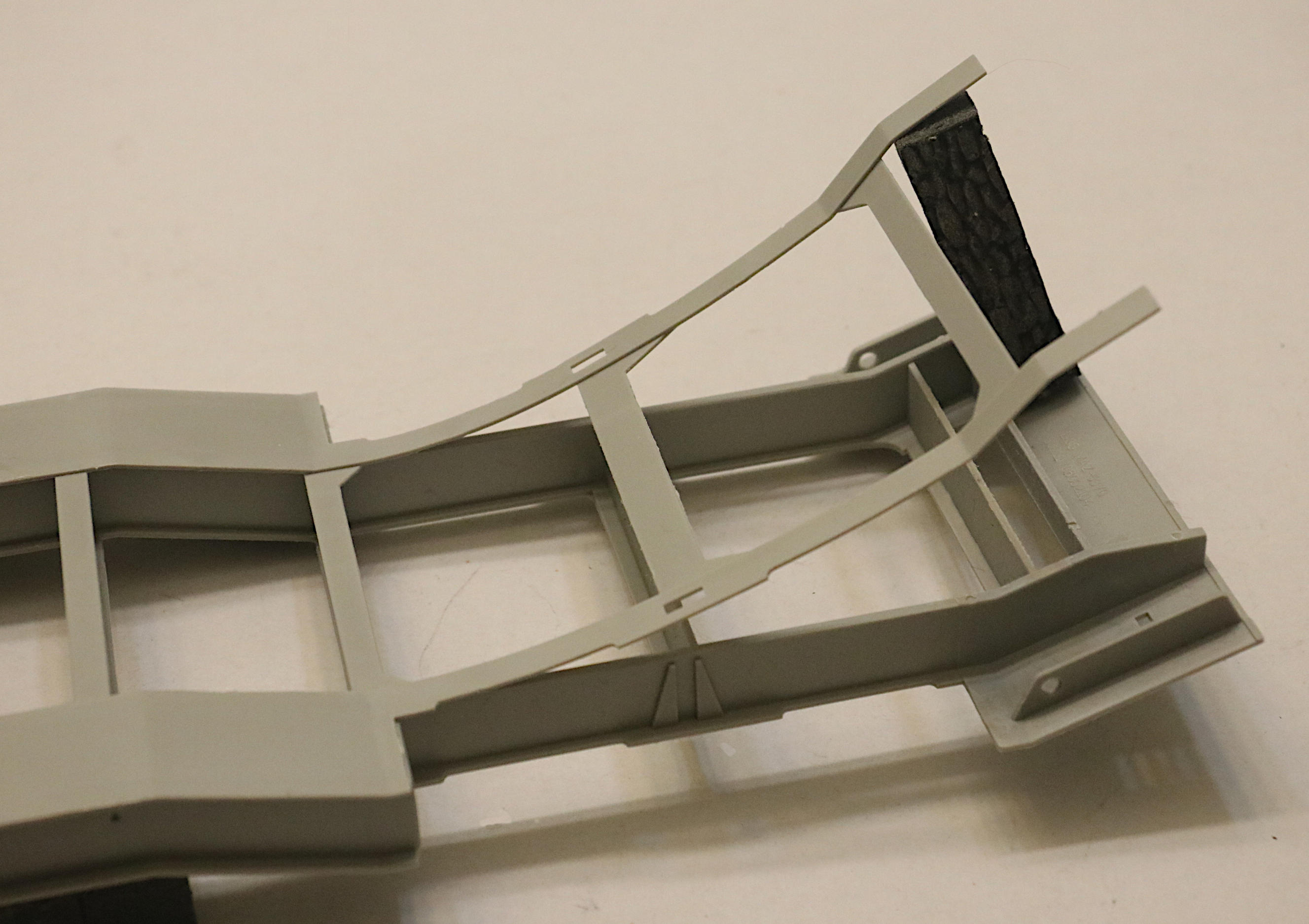
FIRST ~ A minor problem found: When properly assembled, the gooseneck has a small gap in the area indicated below. It is possible to bend this plate downward and glue it but what is supposed to be a massive steel plate will then have an odd looking, unnatural curve to it. I chose instead to fill the gap with a small Evergreen strip.
. .
___________________
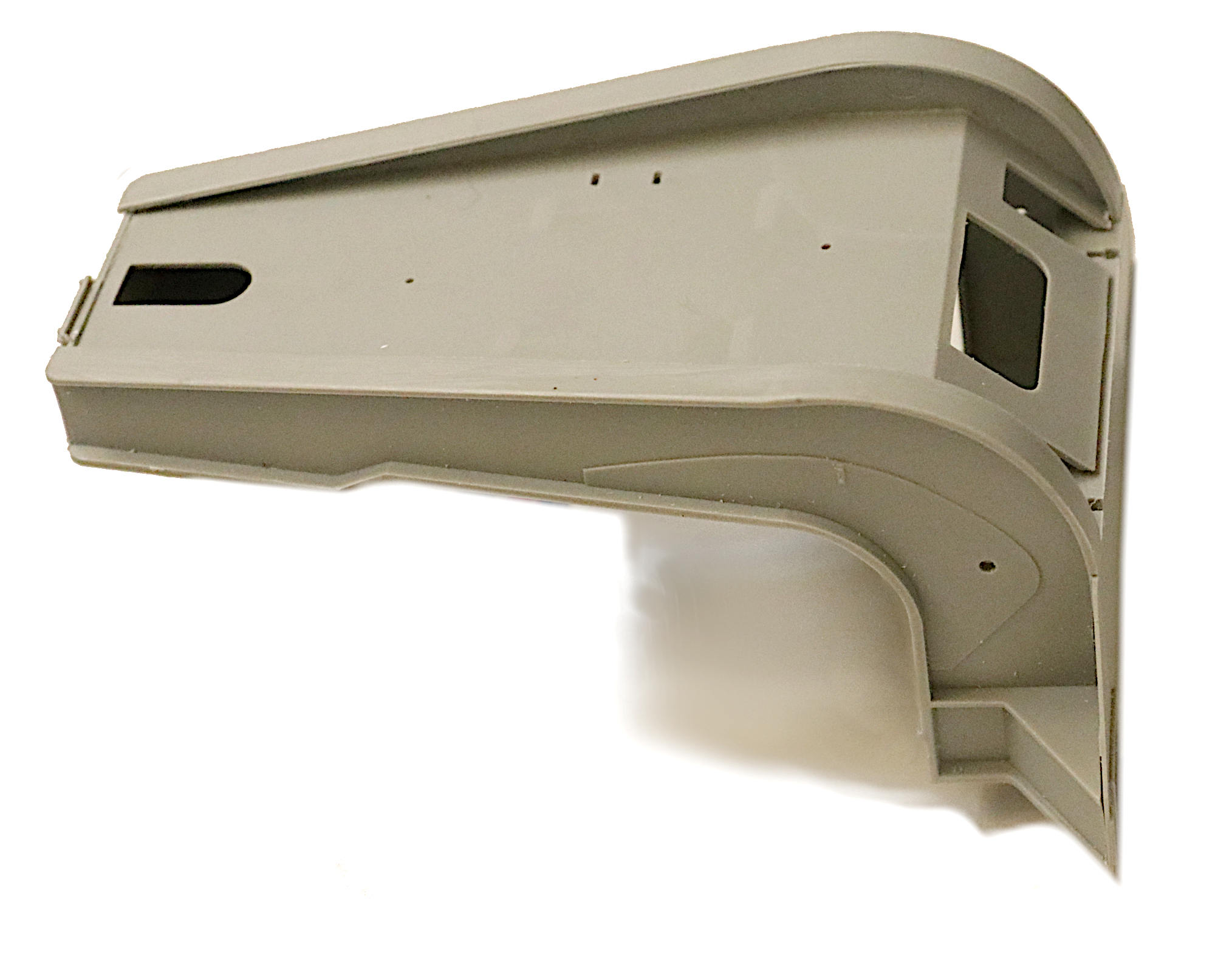
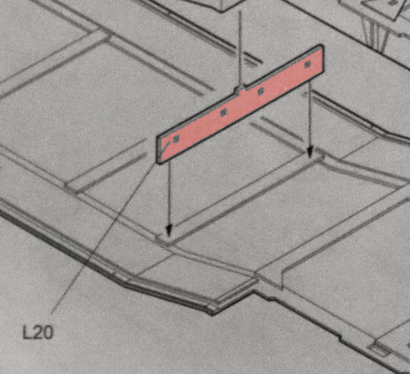
And now for a small “Oh, by the way:” That one cross member (Part L20) has four ejector pin marks in one side and they WILL show on the finished model. How is the time to do something about those BEFORE you put the deck together. ~ FYI.**
_______________________
SECOND: I found something that I considered to be a possible future problem so I chose to alter the assembly order here.
The instructions would have you assemble the upper and lower deck plates and only then attach them to the gooseneck.
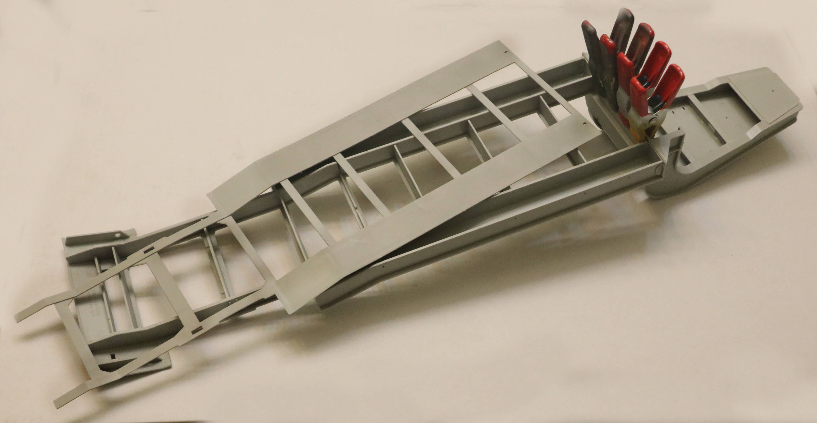
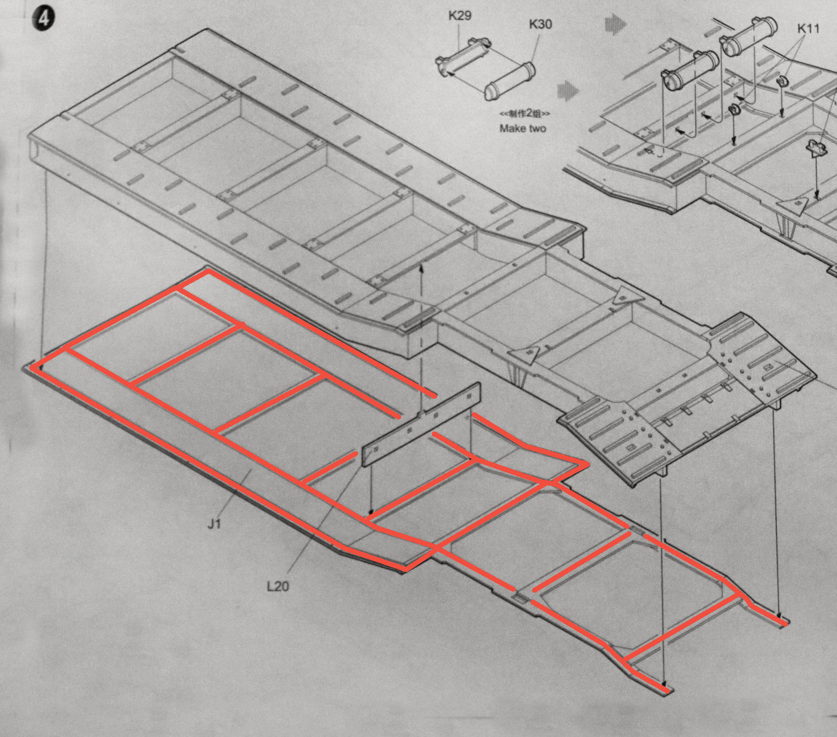
Possible Future Problem: This large flat seam area where the gooseneck assembly meets those massive welded box beams seemed to me to pose a possible future problem. Those two square beams meet the gooseneck solidly enough but the two flat cross members (actually one solid steel beam on the real trailer.) that should touch for extra glue contact area at this union, instead had a very small air gap between them.
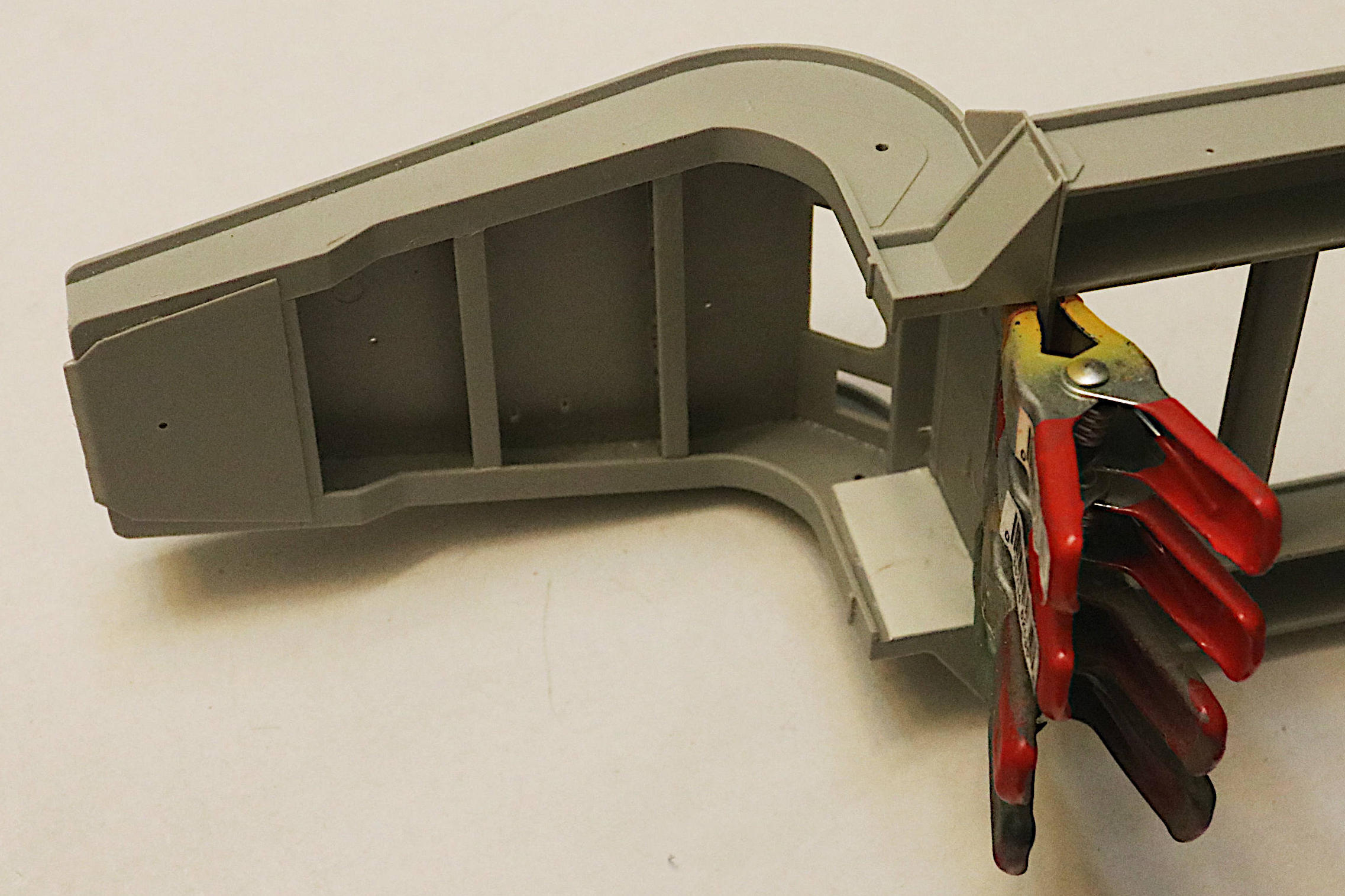
I considered reenforcing this area with #1 Super Glue or #2 adding a thin shim of sheet plastic, or #3 even screwing them together. However none of these work arounds sounded as good as just having the two surfaces meet under clamping pressure and somewhat dissolve together using old fashioned plastic solvent.
But if I had added the lower deck plate now I would no longer be able to clamp these two surfaces. I therefore decided to attach only the upper deck plate to the gooseneck first, clamp it solidly until it dried and then attach the bottom deck plate later.
I figured the more of a broad contact gluing area there was between these two parts, the stronger this very important joint would become.
Clamped this connection overnight and allowed to dry.
. . . . and Voila!
OK - another small change to the assembly order:
So now it is finally time to add that bottom deck plate. However there are such a huge number of beams, struts and cross members that all need to have glue applied before clamping those bottom and top plates together to let dry.
It was going to take SO long to apply the glue to all those many parts, I thought the first area might be starting to dry before ever getting to the last part. So again I changed things up a bit.
This is how the instructions would have you apply the glue all at once:
And this is how I actually applied the glue - now in two steps:
(Leaving that little floppy end piece around the wheel welds to be glued down later.)
Those tail end parts on the bottom deck plate are just so thin and flexible I knew I could leave them for later and concentrate on gluing the real “strong back” portion of the trailer first.
Basic trailer assembly complete:
Note: I may live to regret this but I am using a bead of glue laid down to simulate the many weld beads to be seen on this trailer.
I have seen others use some resin decal style “Weld Beads” but while neatly done, they seem too large and I feel they almost draw attention away from the trailer itself.
As I say, I may live to regret this but;
- Some model judge may one day say; “Hey, those are all glue smears and you just painted over them!”
We will see.
Nice work on the trailer Mike. I recall building the 537 , those same pitfalls. I added a strip like yours on the gooseneck, then using glue w a knife tip creating a weld bead across that highly visible area.
Looking forward to your updates