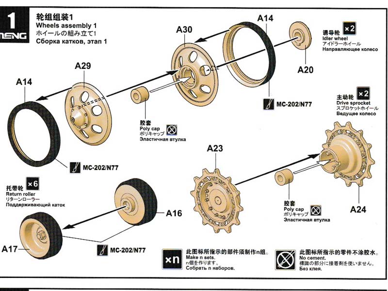
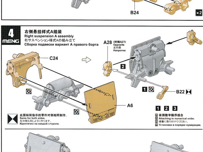
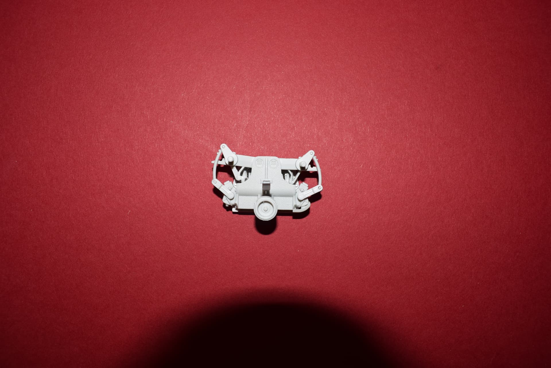
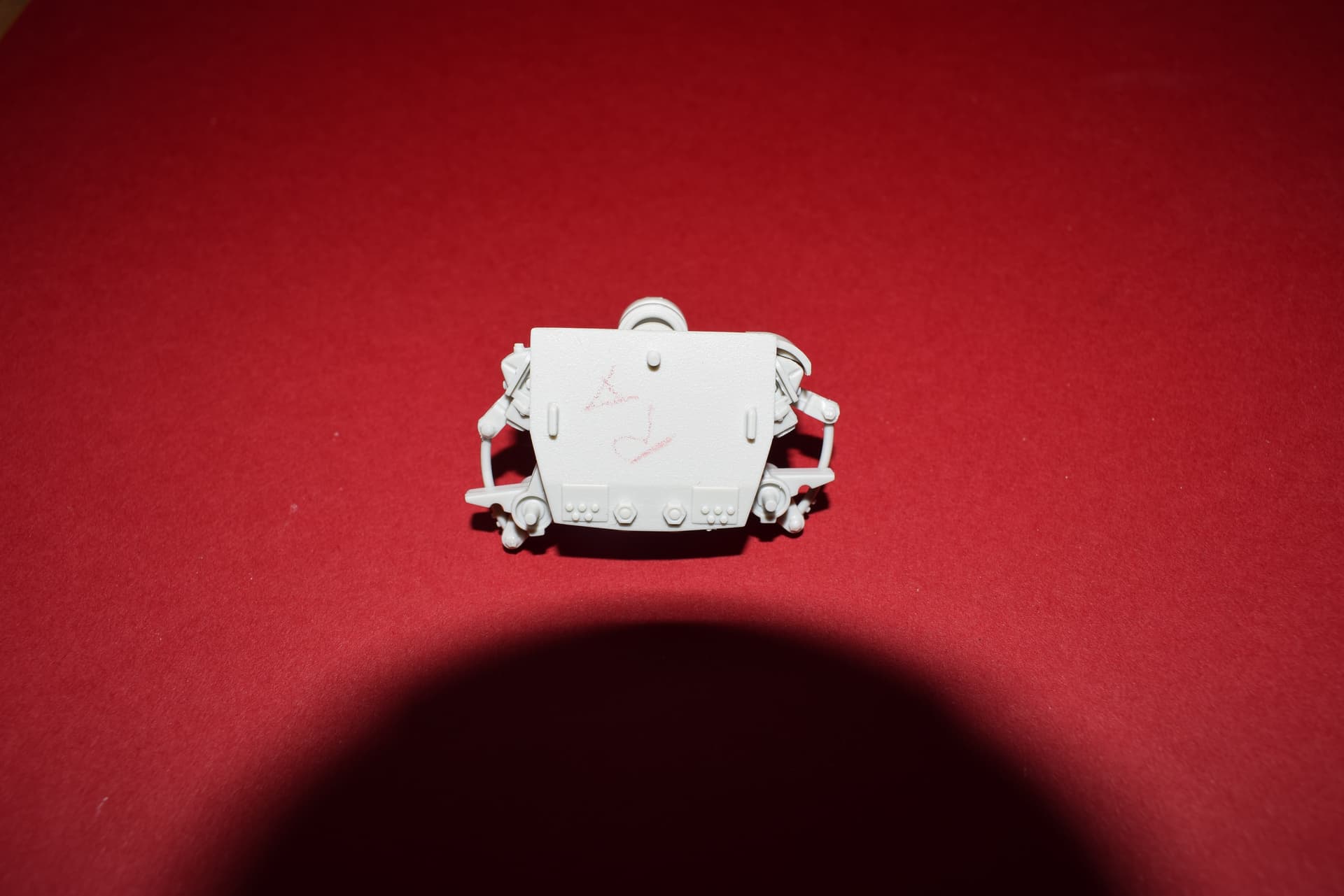
So here goes the build of Meng’s Chieftain Mk 10 and it starts with wheels stations. Each station needs to be marked as they are different and so I have marked the unit station on the rear so RA just stands for station A right side. The wheels are over engineered in my opinion and I did not enjoy the clean up one bit. Another annoyance is that the sprue gates overlap the part that makes clean up even less fun.
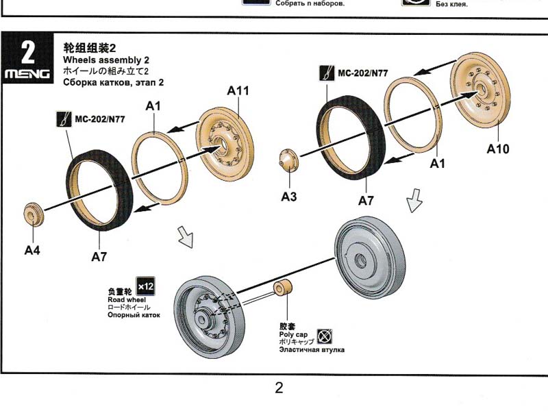
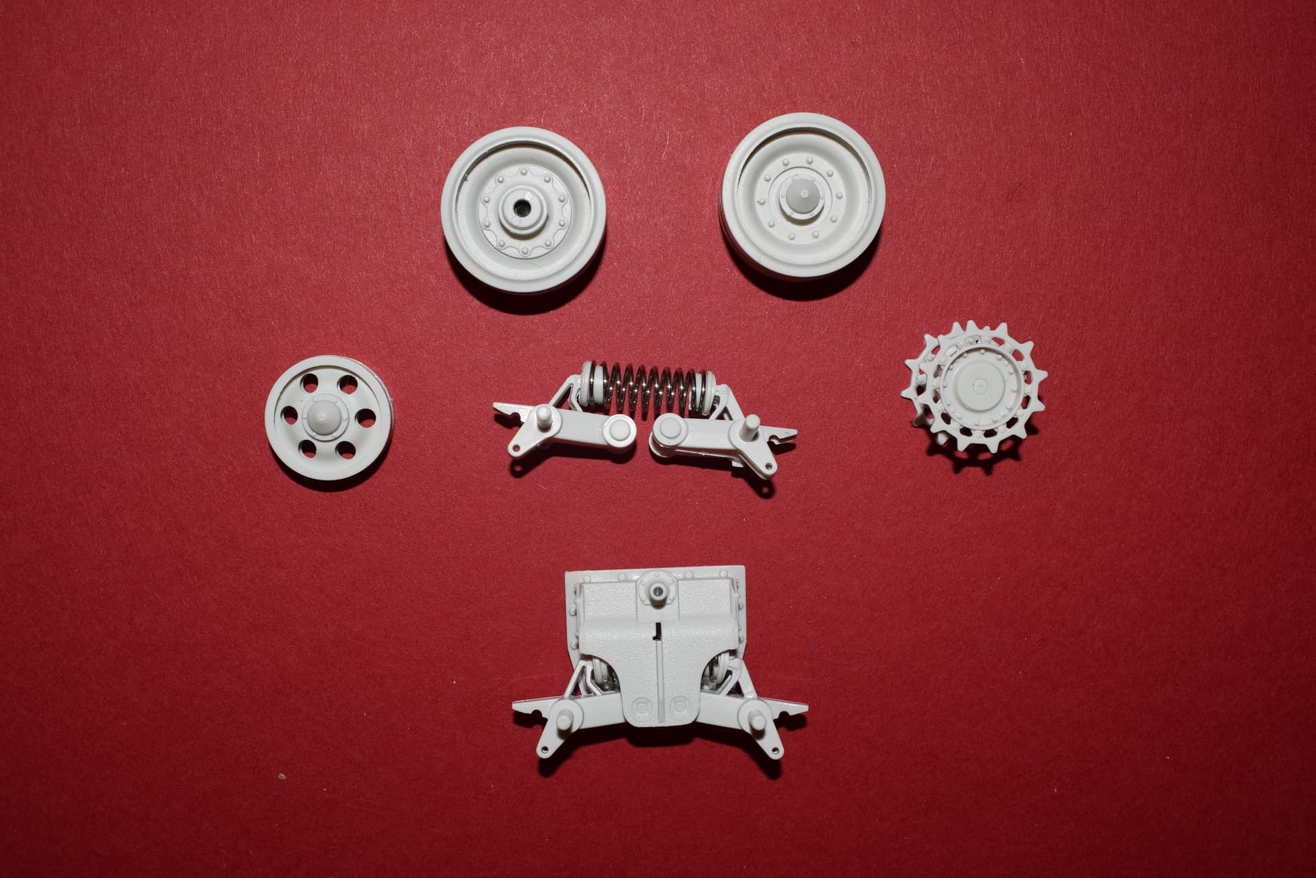
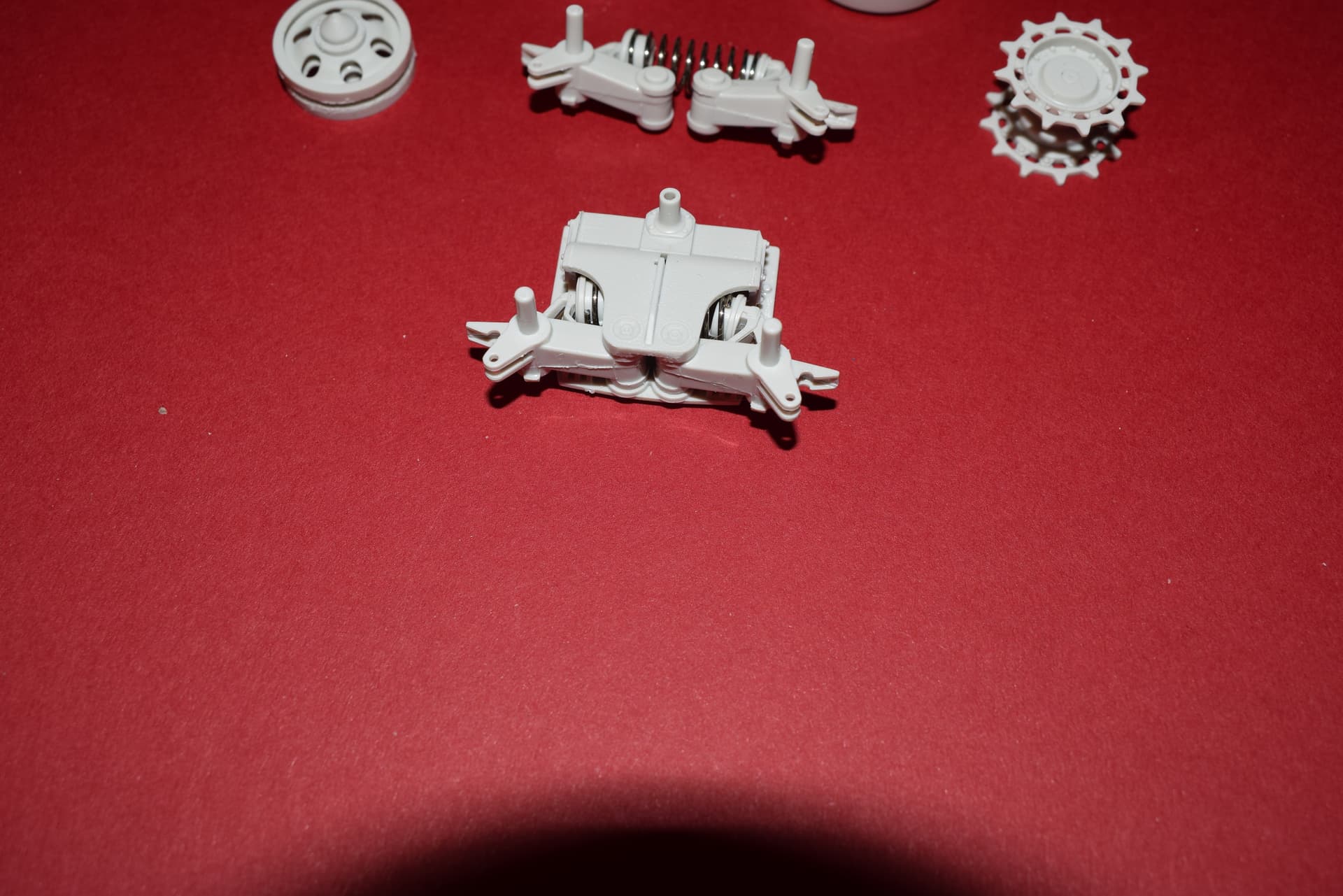
The units are workable due to a spring and various locations are good fits for the most part. An issue I encountered was the for push fit pins on the rear of the arms come out and so I secured them on the rear with Micro Kristal Klear.
12 Likes
Subscribed and along for the ride!
A++ on subject & kit choice.
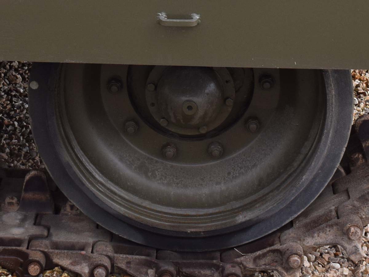
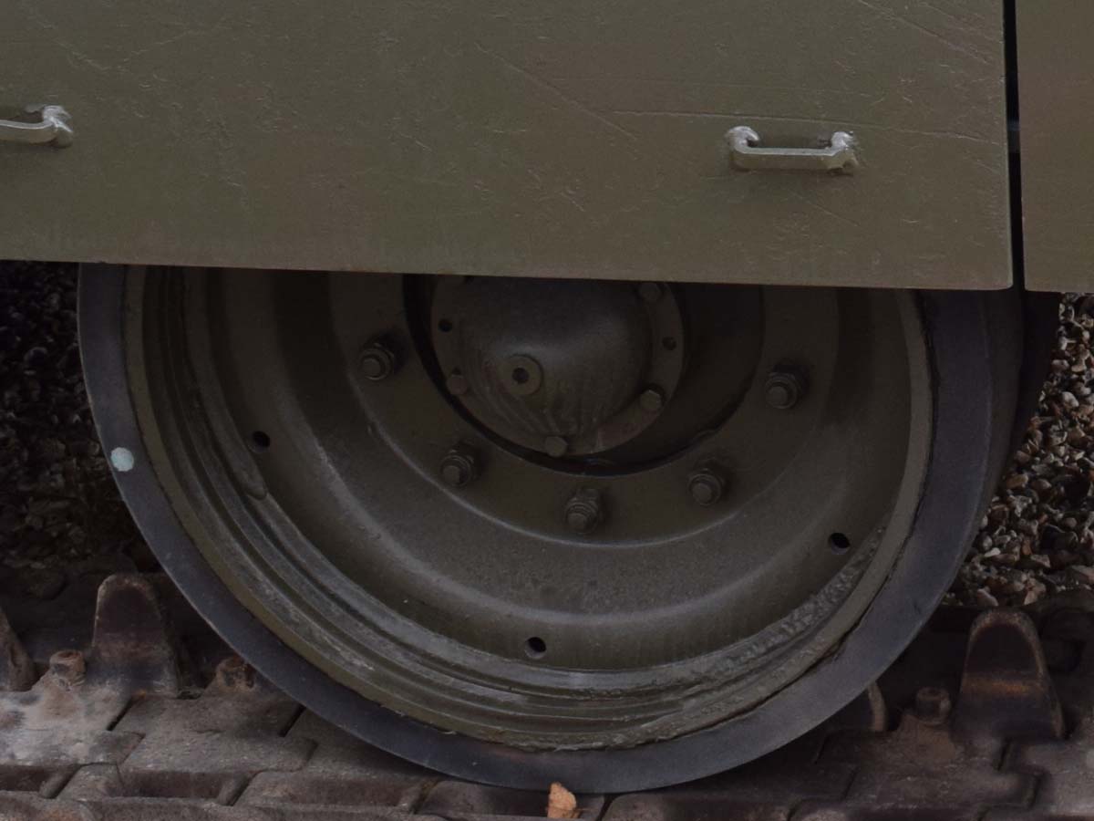
I have noted that there are at least two wheel designs used on the Chieftain and I have see them mixed so anyway know anything about specifics?
1 Like
Ah great another build of this kit, look forward to seeing more! Nice one Darren.
J.
If I remember correctly, we were just advised the holes were there for pressure relief and to help prevent the build up of mud etc and to prevent it clogging up in between the road wheels.
Similar holes are on Centurion wheels too, though not sure whether all were like that or not, so it should not surprise to see them on Chieftain?
Mal
The purpose of removing mud would make sense but they seem to be too small. The other reason for holes in wheels is to lower the overall weight and that does not seem to apply here either.
Guessing time
Holes are too small to allow much mud to pass through, especially if the mud and muck contains solid particles (small rocks, pebbles, gravel, pieces of wood or other resilient organic material).
Soft mud would be squeezing out between the roadwheel discs before it starts coming out through those holes. When pressure builds up the pressurised mud will take the path of least resistance to get out of the squeeze …
I could imagine that those holes could be useful to stick the tip of a pressure washer into when washing the mud out from between the wheel discs.
It could also be a feature to facilitate handling during manufacture.
I wonder if those roadwheels get balanced like the wheels for a car or truck?
Thanks for posting this Darren, I’ll be following with interest, 
 .
.
G, 
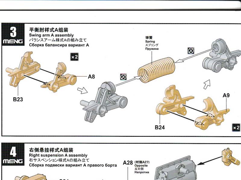
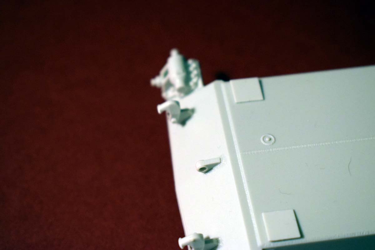
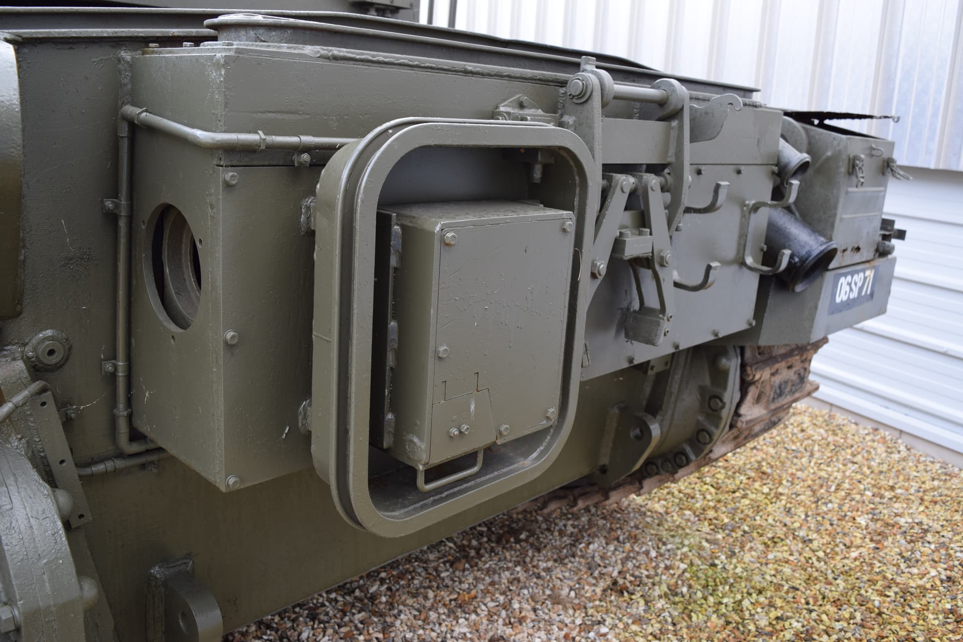
Moving to the lower hull and some square parts are added, I have not got a clue as to the purpose of these parts unless it is just added protection for the four corners of the hull. Moving to the front and Meng seem to go from over to under engineering in that the shackle locators are moulded as part of the mounting bracket? However still ticking along and no issues.

2 Likes
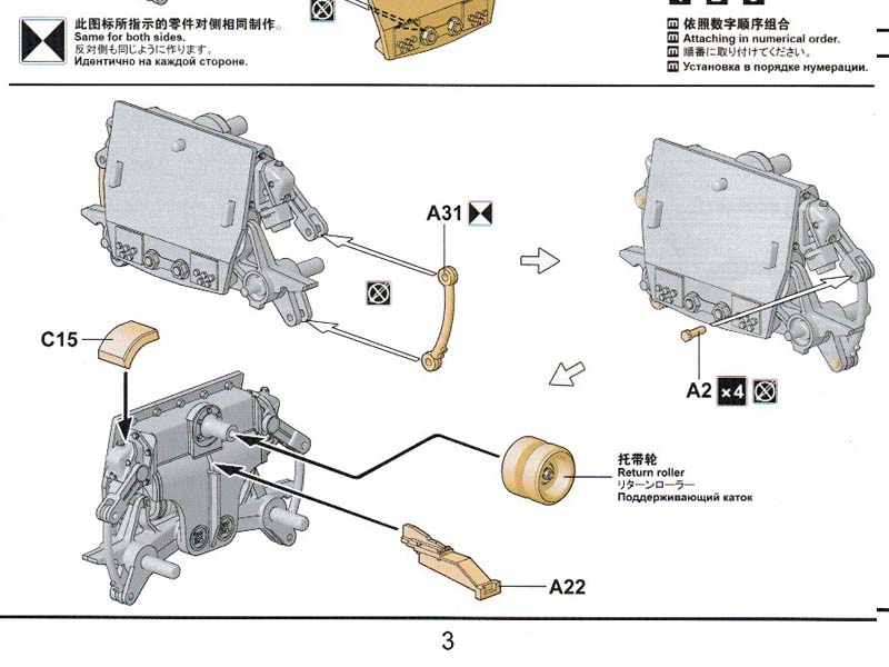
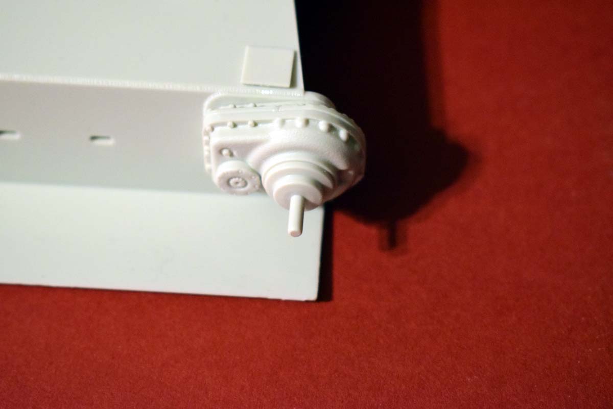
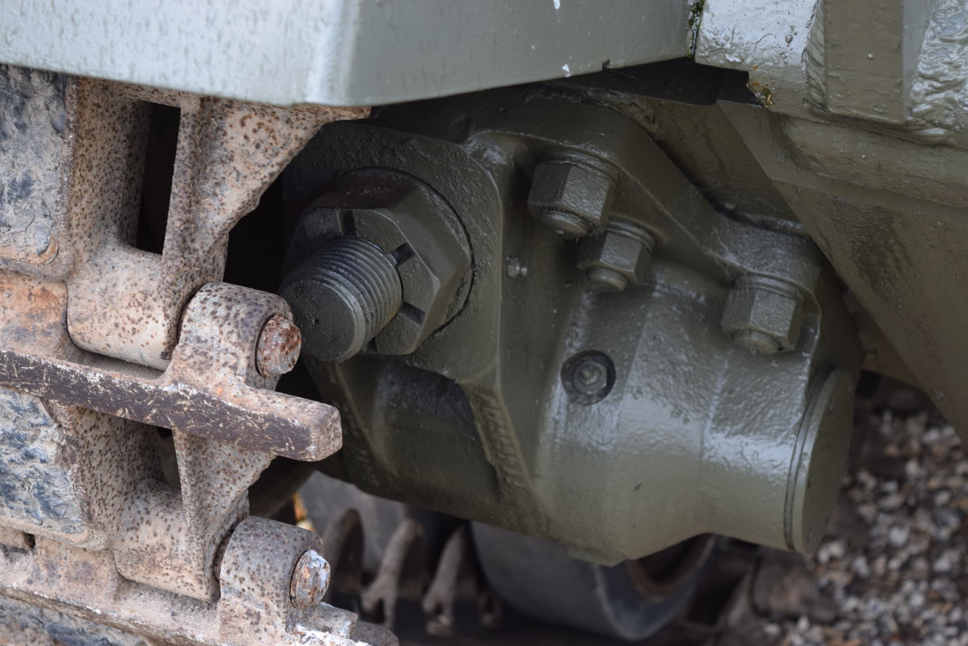
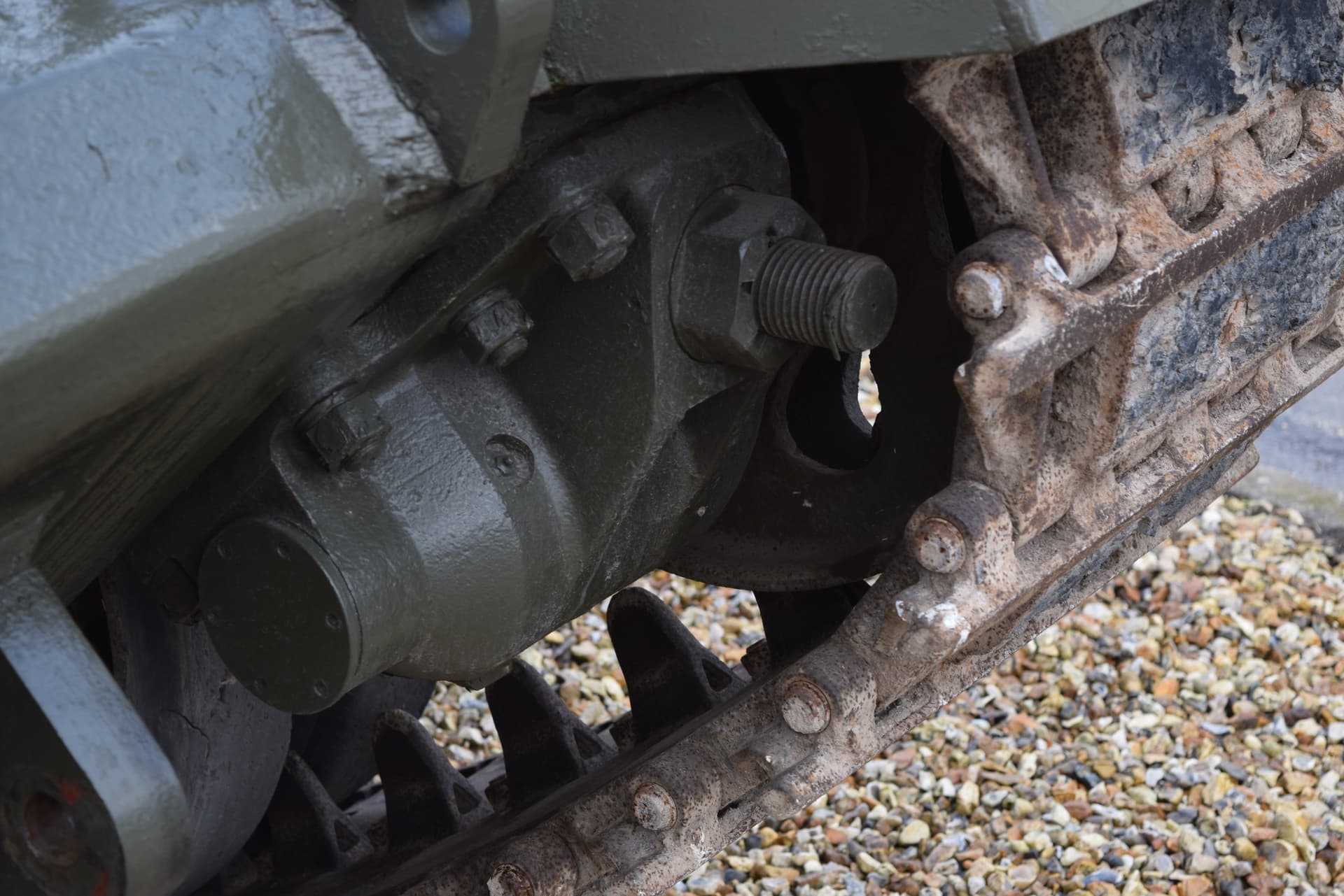
The bell housings and idler mounts are next on the list and other than the pain of sprue gates going onto the face of the moulded parts a good fit and secure mount is gained; one minor concern the idler adjuster is preset for you and so the tracks need to fit well. There is a filler cap/port cap on the left side and I do not know which it is or for that matter why it would be placed in such a difficult spot to utilise.
Some holes then need to be drilled in the upper hull plate and I am pleased to see Meng tell you to use a 1mm drill bit. Two flat plastic parts are added to the interior of the upper hull which close up the body and support the upper hull when the lower and upper hull are mated. Meng does not mate the hull until stage 18, but I have looked closely and see no reason for this. So I have secured the hull now as there is nothing to break off and means finger placement for any encouragement is an easy and safe procedure. I cemented each side working in a circle to insure I was happy with fit and location.


2 Likes

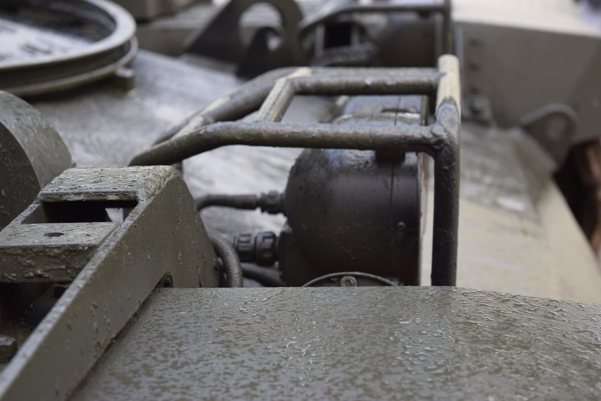
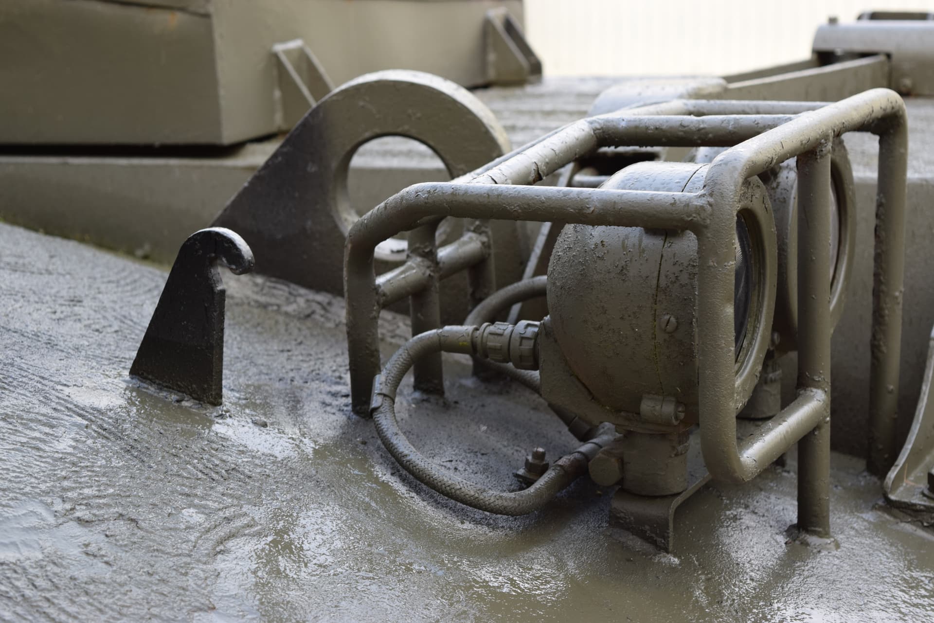
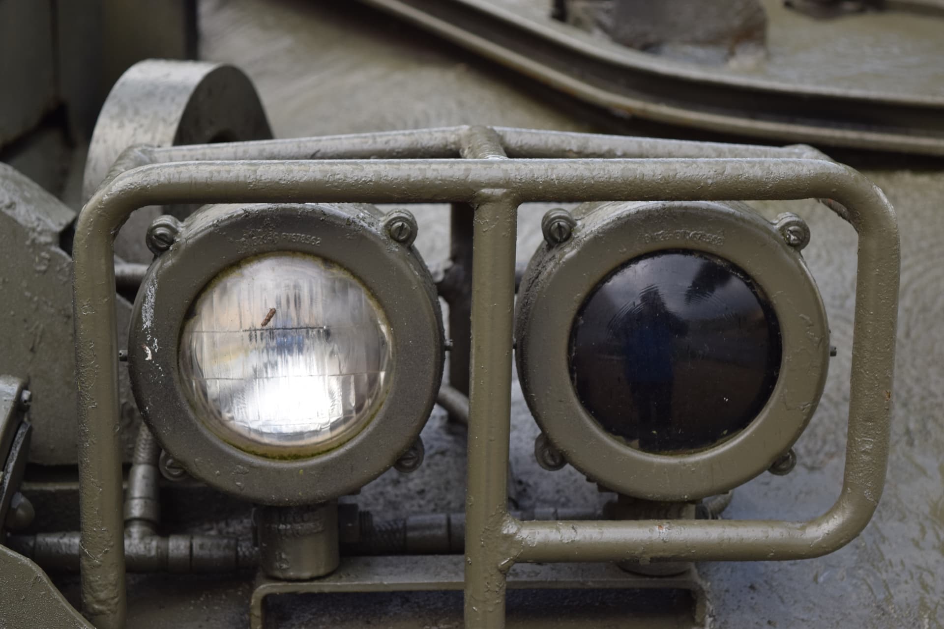
Fitting the front lights was easy enough with clean up of the guard being the hard part for me. Good location is provided for the parts to the hull but nothing I could see when bringing the guard pieces together. I have not added the lenses as I feel I will be able to add these near the finish following detail painting. The upper hull and securing points are easy enough with the larger ones being side due to an off set locator. I have included wiring details for the super detailers.

4 Likes
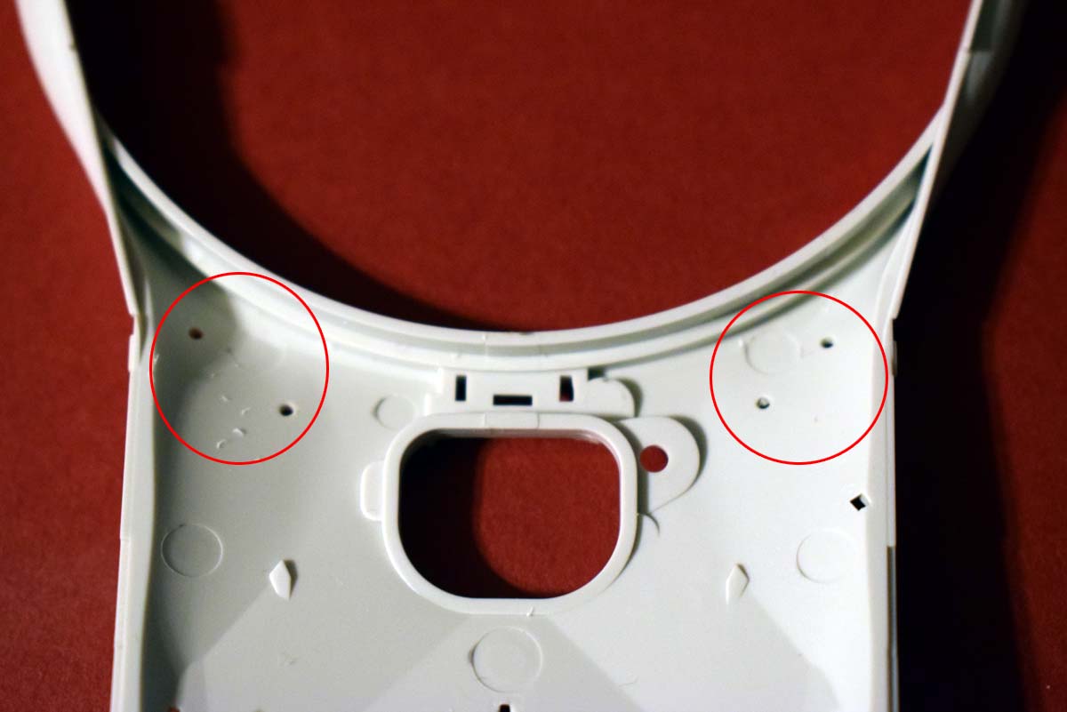
Next up is what I believe to be the splash guard for the driver and so should be shown as optional. The parts are not clearly shown as regards part placement so the parts should be brought together rather than parts (C17 and 18) pushed through the opening; the instructions could be better here. I do not know where this part is stowed when not in use. As you can see in the images there is an ejector pin mark that needed sanding out.

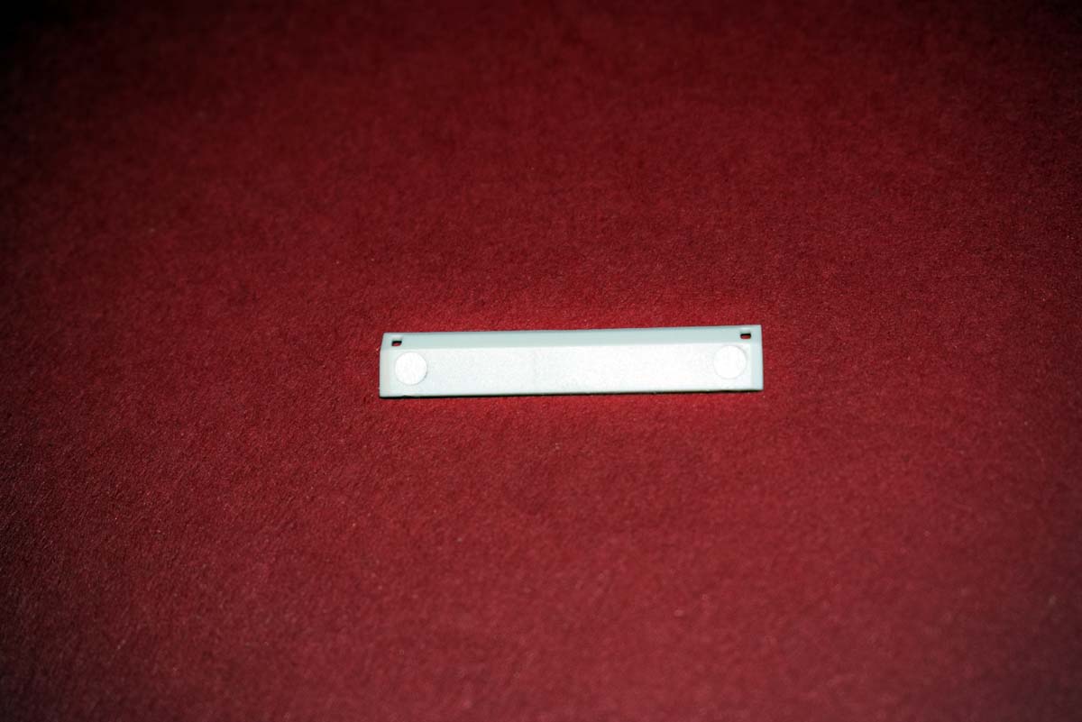
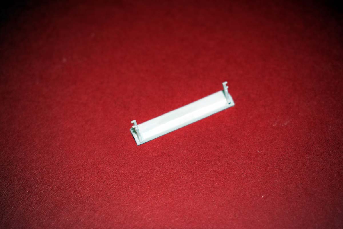

3 Likes
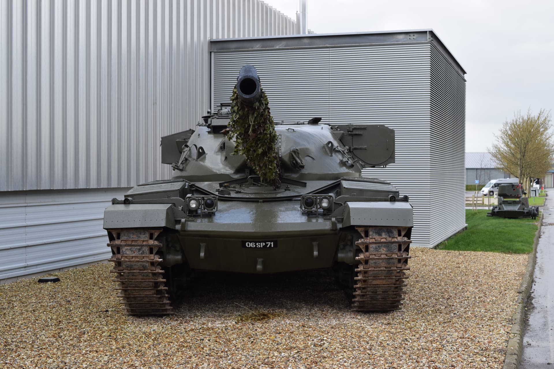
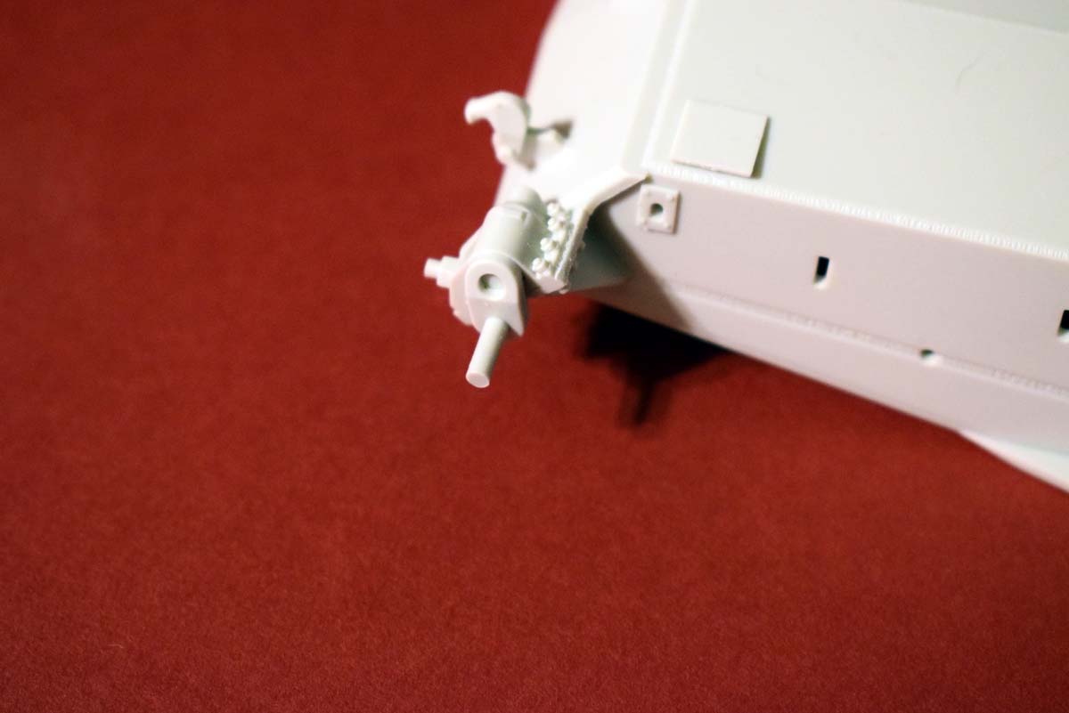
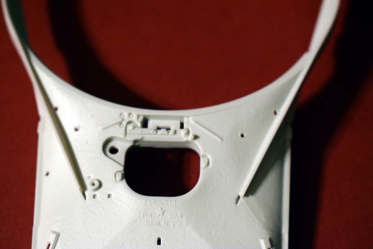
The tow hooks are probably easier to be moulded onto the brackets as they were always fitted on service wagons. The image without them is a service prototype, and now its a museum piece it more than likely wouldnt have the tow hooks as they would of been removed when it was taken out of testing/service.
Part D38 is the dvrs splash plate and should always be fitted so its not optional hence it didnt have a stowed area. The only time it would be removed for when the wagon had the dozer blade fitted. Parts 17 & 18 are fitted to the front inner upright on the headlight guard, about half to 3/4 of the way up it. The splash plate should sit with a slight forward angle when mounted correctly. And as you pointed out, the splash plate mounts are flush with the rear and do not push out through the front.
It’s molded in a off white color?
Johnny: thank you for the information and confirmation, the tow hooks I have always seen fitted to service vehicles and was only pointing out they are moulded as a part of the brackets and so not as detailed as they could have been.
Dan: No the plastic is a light grey and it is just the camera flash washing the base colour out.
1 Like
I think the square plates at the bottom of the hull are jack pads.
David: thank you for that information.