MFH 1/9 1933 BSA Blue Star Build

Knowing next to nothing about motor bikes, I usually quite quickly get lost in yours and Michael’s technical discussions such as what the two of you were discussing about the chain and links. But like with all modeling, the finished piece speaks for itself. That chain is amazing.

joel

I agree it was fiddly to clean up the roller. I would have though it easier to make them out aluminium in such a way so you would have to flatten the tip as well. I am guessing they design chains so it is one size fits all in that scale so they have volume on their side. Maybe that would make the chain too light.

Lots of progress lately - wheels done and mounted along with final drive chain, chainguard , primary chain case , rear brake arm and rod/adjuster .
Number plates done along with tail lamp . MFH supply lenses for tail lamp in clear resin. Number plate illuminator left clear and tail lamp lens painted with Tamiya clear red .
The kit supplies decals reading “ BSA Blue Star “ for the number plates . Many restored bikes do this rather than have a registration number . I wanted a correct albeit fictional British number . With help from members of the UK based Norton owners club I was directed to a site that explains the system used and the letter codes assigned to different regions . I had purchased Roman typeface dry transfers from Woodland Scenics . I didn’t take into consideration they supplied more of some characters/numerals than others . As I needed 3 sets of letter / numeral combinations ( one set for the rear plate and two for the front “ pedestrian slicer” on the mudguard ) I was limited in choice . The only number I could create three times was 610 or 910 and only by inverting a 9 to create a 6. I wound up with AA 610 . To the best of my knowledge this would have been Hampshire in 1933 . Any members from across the pond may please feel free to correct me on this - what does a yank who drives on the other side of the road
know .
I’ve also painted and installed the two panels on the sides of the fuel tank and painted and temporarily installed the tank top instrument panel.
This will have to be removed as I need to decal the side panels and clear coat all .
Center stand built, painted and installed- still needs it’s spring .
Finally , I’ve made a base of Cherry and permanently mounted the model by screwing up through the base into the tires . The rear tire is clear of the ground while on the center stand so I made up a spacer from aluminum tube to support the considerable weight of the model - I don’t have much faith in the soft white metal center stand.

Next task is to backtrack and catch up on lots of fragile little things I left off until the model was mounted and could more safely be handled.
Thanks all for the interest and comments.
Cheers- Richard

1 Like

Richard,
If I didn’t know better, your pictures look more like another real bike restoration then a model, even if it’s a 1/9 scale MFH kit.
The close up of the rear wheel, chain and chain guard completely fooled my eyes. I’d still swear that it’s a real bike. Even the wheel spoke adjusters are just like what we had on the wire wheels on our MG’s and Triumphs to correctly align the wheels, which I never could get perfect. So easy to hit a curb, yet so hart to fix the wheel.

joel

1 Like

Thanks Joel - I gotta agree- please believe me no egoism here - the close up of the chain says it all about these MFH kits . If it weren’t for the wood base I would be fooled too and I built it .
Lots of effort and expense in these kits but boy - they are truly in a league of their own.
Thanks again for the kind words.

Beautifully done Richard. Such a neat looking bike.

cheers
Michael

1 Like

I can only echo what has already been said. Absolutely amazing.

1 Like

Ditto from me Richard, stunning work mate!

Cheers, D

1 Like

Another taste of MFH detail - I’ve assembled and installed the headlamp . The bucket , reflector and mounting brackets are supplied in white metal. The rim is an aluminum turning and the lens , pilot lamp bulb and headlamp bulb are supplied in clear resin.
That’s right - you even get the lamp bulbs !
Also supplied is black plastic tubing to represent the wire loom .

In this shot can be seen the front brake arm and rod and the speedometer drive at the front wheel , the Blue Star badge on the timing cover and at the gearbox the positive stop foot change mechanism.

Here we have the footrests , gearchange lever and kickstart lever, all with rubbers. Also the foot brake pedal for the rear wheel brake .

The panniers are built up and primed . They are engineered to open and close but I cemented all closed. I’m not a fan of operating features on models and the paint on these metal components chips if you look at it wrong.

And lastly I’ve begun to work up the exhausts.

3 Likes

Richard,
I know that I just keep on repeating myself that your build is practically impossible to tell from the real bike as a restoration.

The headlight lamp just blew me away. The detail in 1/9 scale seems even more complex and complete then in the usual 1/12 scale.

joel

Looking good Richard. Are you going to “blue” the pipes?

cheers
Michael

1 Like

Thanks gents - I believe I will try to blue the pipes a little - I have big shoes to fill after seeing the effects Michael achieved on the Duc . I can always buff it off if I don’t like it.

1 Like

Very cool, with those light bulbs. Quite an impact those small things have.

2 Likes

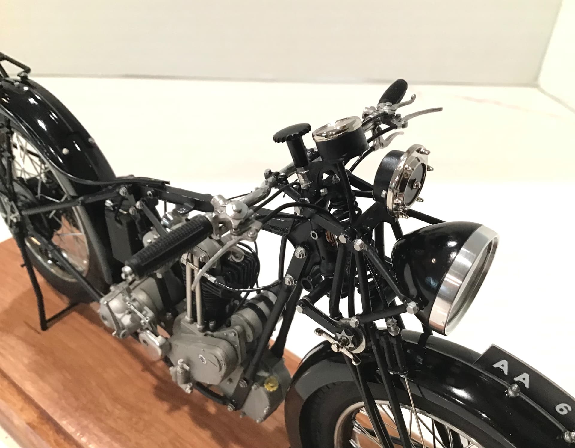
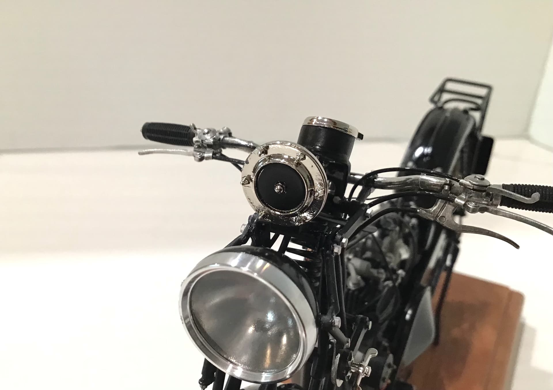
Moving forward with the handlebar group and the attendant cables/wires. MFH has included all - very complete indeed.
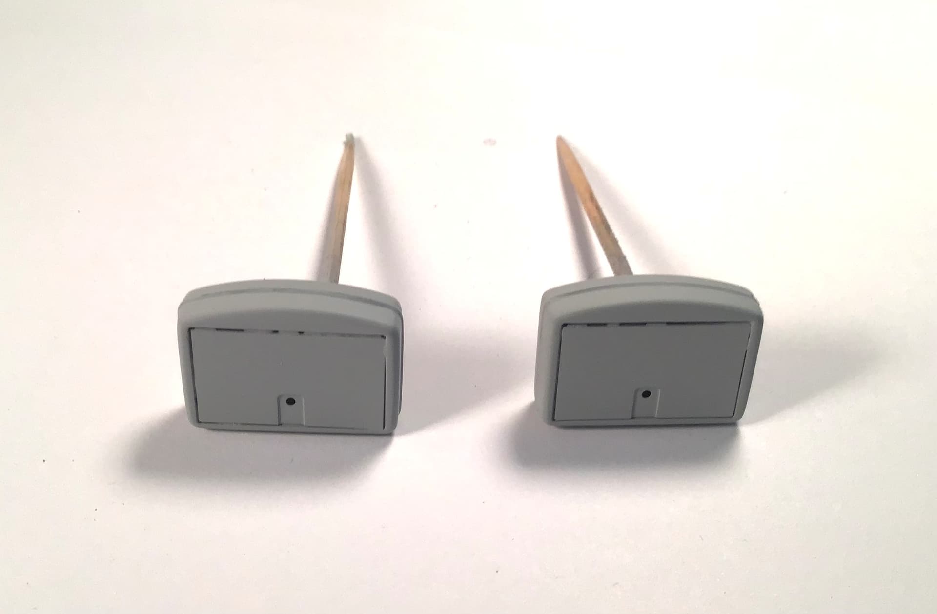
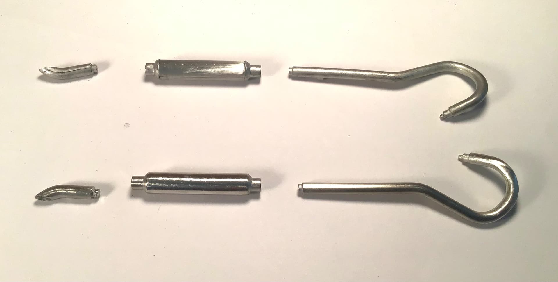
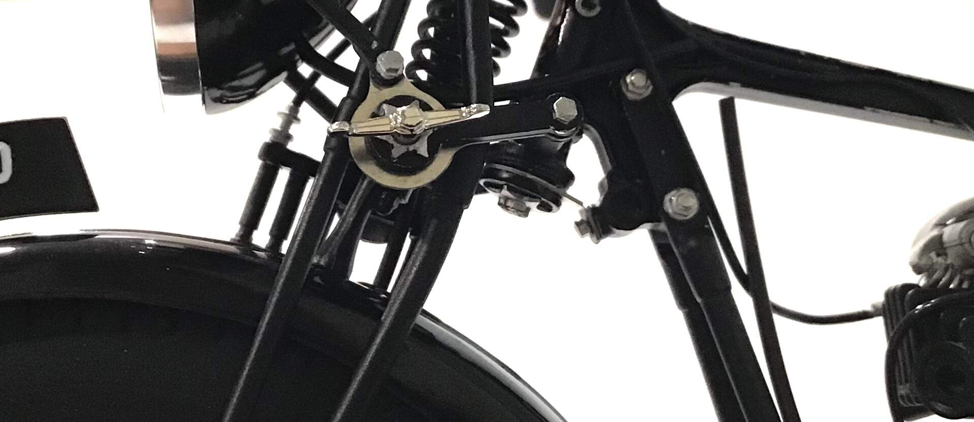
Here is the friction steering damper-


On the right handle bar can be seen the front brake lever, throttle twist grip, air slide lever ( choke ) and horn button - MFH include the wiring for horn button on right and dip switch on left.

On left handlebar can be seen clutch lever , manual ignition advance/retard lever , valve lifter
( compression release ) and dip switch.

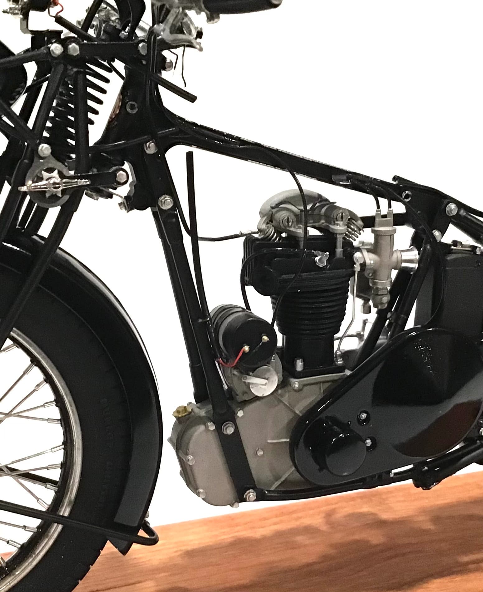
For the gear heads amongst us some details .
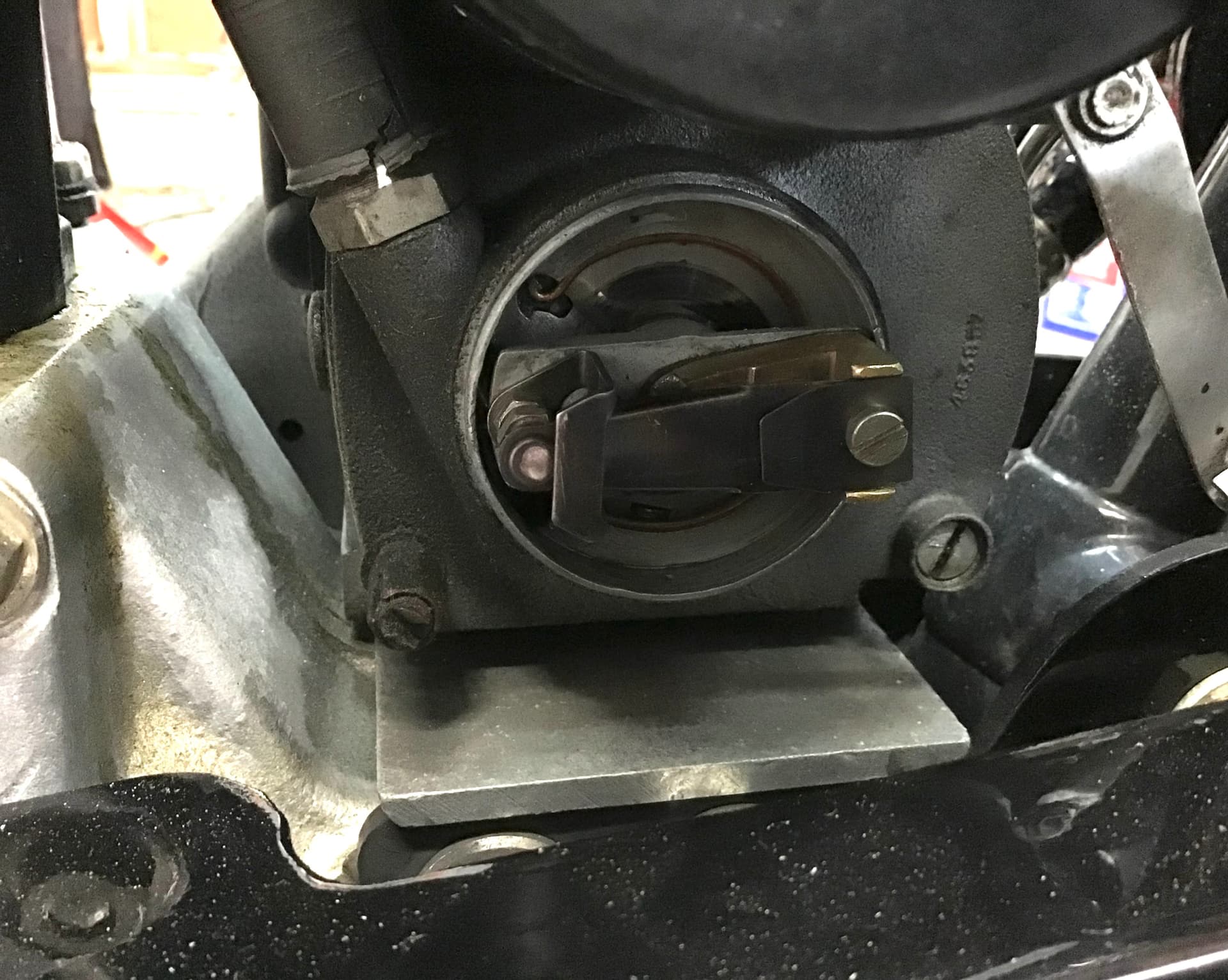
Bikes of this era and up through the 50’s did not have auto advance for the ignition timing . The long lever you see atop the bars by the clutch lever rotates a face cam in the magneto that opens/closes the points. Unlike what most of us are used to seeing, the cam is stationary ( except for the few degrees of manual rotation by the advance / retard lever ) and the points rotate. Ignition timing is generally set on machines of this era by piston travel rather than degrees of rotation - i.e. on my Norton (IIRC ) the points open at something like 5/8” BTDC on the compression stroke . The magneto shaft is tapered and keyless and driven by a chain from a cog on the intake cam. The mag sprocket is set loose on the shaft and the piston is brought to the proper position. A slip of the thinnest paper ( cigarette paper is the traditional choice) is placed between the points and the shaft is rotated until the points just start to release the paper. At this juncture the the mag sprocket is driven home on the shaft with a tube or socket around the retaining nut and a hammer, then the nut is snugged up . A little further along in this post will be pictures of the points and face cam.
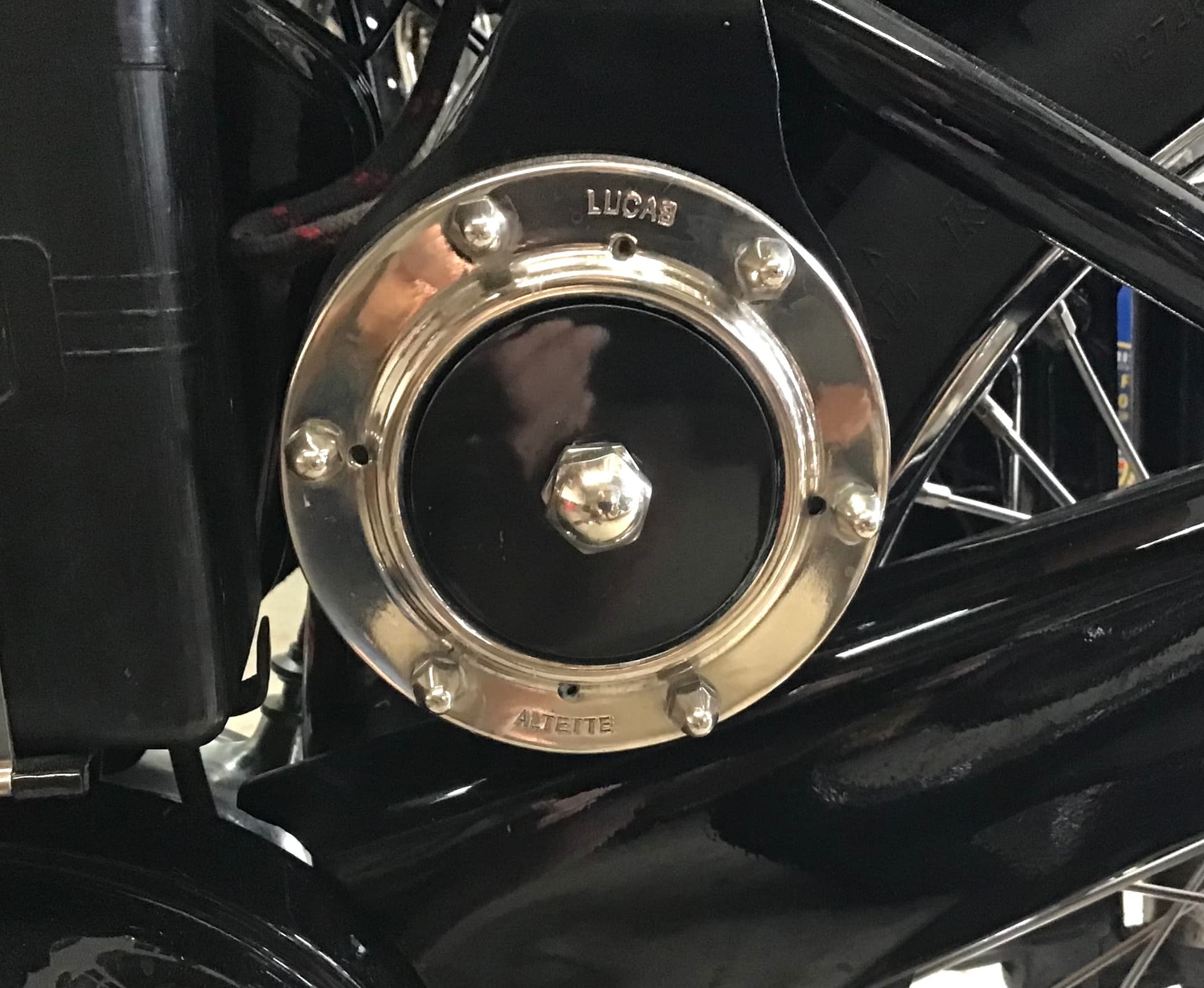
Here is Lucas Altette horn , including wiring . Front view in above picture.
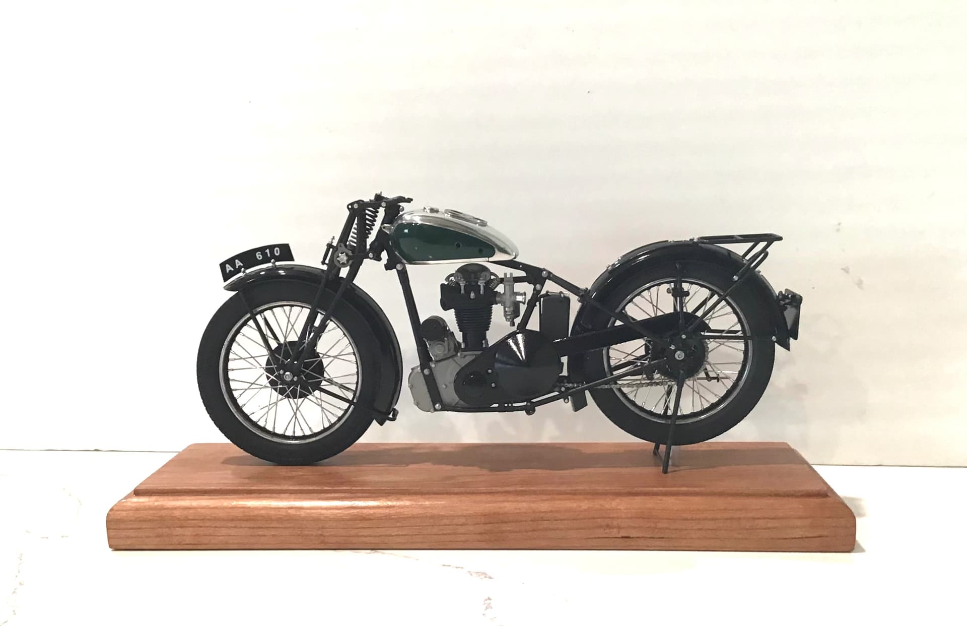
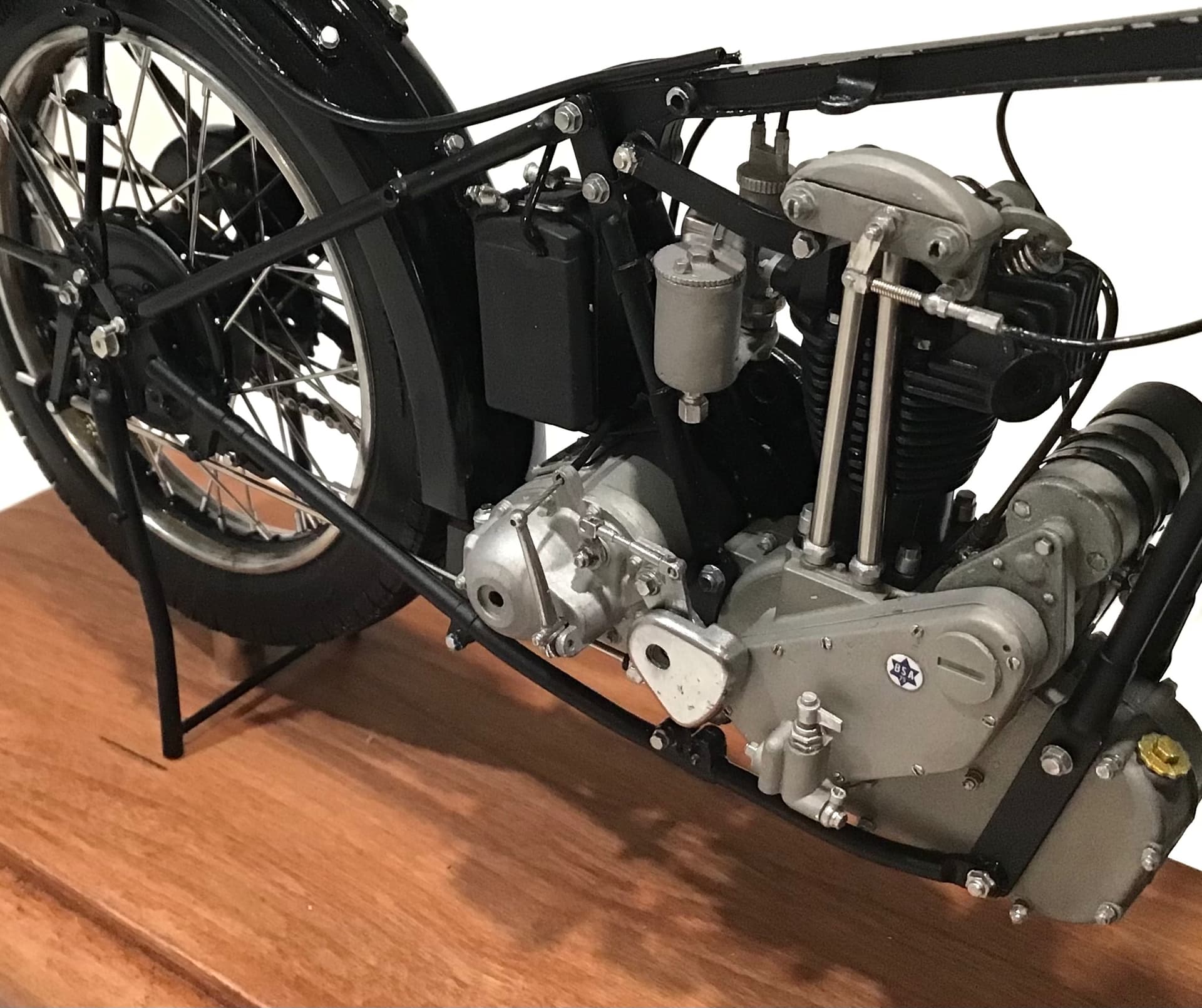
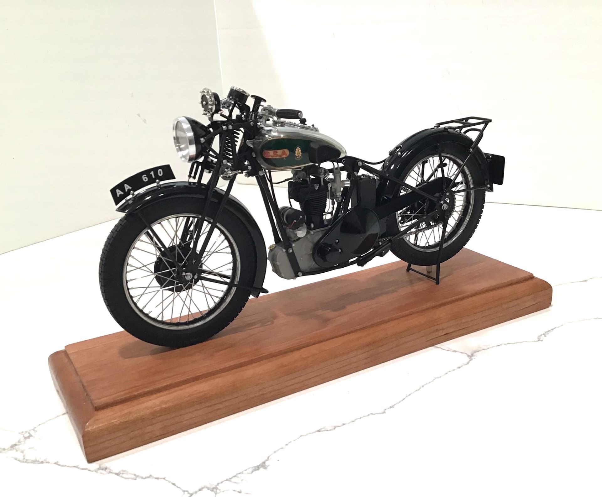
The model …

… and the real thing…

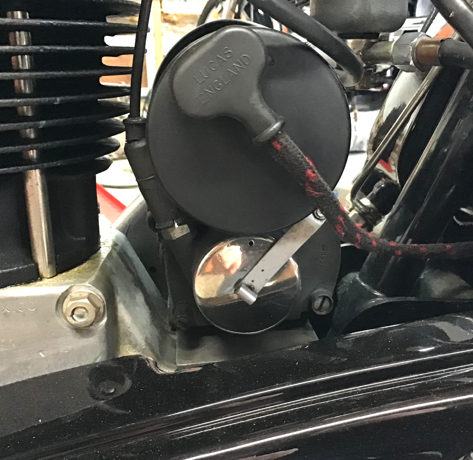
Here is the model Magdyno - magneto on bottom and dyno ( generator) on top , complete with wiring.
Note the points cover and it’s spring retaining bale - just like the real deal .The dyno / battery only provided current for lighting and horn - ignition provided for solely by the magneto. Dynamos of this era were three brush and did not require a voltage regulator - they were problematic and later units , including the actual one you see on my Norton were two brush with regulator.


The real thing - in second pic can be seen the rotating points and their face cam …


Here is a shot of the gearbox end of the clutch cable on the model … MFH really nailed this detail.

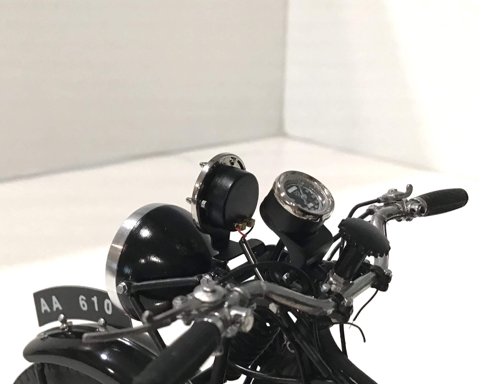
and the speedometer, complete with separate needle and lens …

Thanks for looking - more to come.
Cheers- RT
Addendum… more for the gear heads .
The valve lifter is a very simple device to release compression for starting the engine . While I am not certain how BSA accomplished this in 1933 I assume that it was similar to the systems I have knowledge about . Most are a simple cam device posed over the exhaust valve rocker . When the lever at the handlebar is pulled the cam is brought to bear against the rocker , cracking the valve open and thus releasing compression. Starting drill for most involves retarding timing , turning on fuel at tank , closing air slide ( choking) “tickling “ the carburetor ( a button that holds the float down to enrich the mixture) .
Kick over slowly until top compression then pull compression release until just past TDC . Release valve lifter to restore compression then a long swinging kick - if all is well it will light right up .
The technique is different for magnetos vs coil/points . Mags produce hotter spark when they spin faster, hence the reason for bringing the piston just past compression. Kickstarting bikes with battery/coil ignition general benefit from kicking at compression. Regarding retarding the ignition on manual advance machines - if you forget and try to light it up with the ignition fully advanced , it is likely you won’t do it again after your foot , ankle and leg heal …

Absolutely amazing Richard, this is gold standard scale replica work in progress!

Your explanations and comparison to the 1:1 give the whole thing real clarity for a non-gearhead like myself.

Bravo sir, bravo !

Cheers, D

1 Like

Richard,
As usual, not being a bike kind of guy I once again got lost in much of what is what and what it’s purpose is. But for me the important thing is that with the level of detail provided by MFH in the kit, and your skill level, it’s virtually impossible to tell the real bike from the 1/9 scale one.

Assuming that you can seal the engine to hold compression, I’d bet that you could get your BSA to actually kick over.

joel

1 Like

Stunning job Richard and thanks for the tutorial on starting historic bikes. It must help that you have such a bike to know how should go together. But I think I will remain a fan of the turn key, push button kind of bike rider :grinning:

cheers
Michael

1 Like

A Milestone of sorts - fuel tank done and installed.
Motorcycle fuel tanks seem to be the epicenter for most .
The components are mostly white metal - tank in two halves, top and bottom . Two side panels , instrument panel and filler cap. The cap is supplied plated as were a couple other items . Frankly I wish they weren’t - some flash on the parts that wasn’t removed before plating and I think the polished white metal has a better scale effect and looks richer . It somewhat cheapens the appearance when seen in conjunction with the polished white metal. If I had it to do over I would strip the plating and polish the white metal beneath.
Three bezels are supplied in turned aluminum for the tank panel - oil pressure gauge, ammeter and lighting switch. The panel lamp is a two piece white metal casting.
Decals are supplied for the gold lining around the painted panels . There is a break in the bottom of the decals for adjustment which is fine but they chose to put it at the bottom front in plain view rather than bottom rear where it would have been hidden by the rubber knee grips. Decals also for the BSA letters and badges.
MFH supply solder in two diameters for the fuel / oil lines . The oil lines are the smaller diameter but they don’t give you enough for both the top end feed the left side that runs from the cylinder base to the cylinder head and the line that runs from the oil pump / regulator on the timing cover bottom to a fitting on the fuel tank bottom beneath the oil pressure gauge. Fortunately there was a surplus of nickel silver wire of the same diameter so I used it for the oil pressure gauge line.

The components for the seat are painted and ready for installation but it needs to be done in conjunction with the exhaust system. More finishing/polishing needed on the exhaust - getting near the finish line.
Thanks for looking-
Cheers- RT

3 Likes

To echo Joel, it does look like the real thing.
Interesting about the chrome plating - I haven’t seen that before in MFH - as you say it is easy enough to polish the white metal.

cheers
Michael

1 Like

Richard,
I’m just plain speechless!! Just love the gas tank and the chrome is polished to perfection. Looking forward to seeing the final update with the seat installed, and then the full glamor layout.

joel

1 Like