MFH's Williams FW07B 1980

It seems appropriate at the start of the 2022 F1 World Championship that sees the return of ground effect cars to slide back in time to an era 40 years ago when they last raced and look at the car that made the most of this aerodynamic feature.

The Williams FW07 was probably the best of the ground effect cars of the late 1970’s / early 80’s before that form of aerodynamics was banned in 1982. The FW07 should have won championships in 79, 80 and 81 but had to settle for 1980 and Alan Jones as their sole successful World Champion. In 1979 reliability issues early in the season cost them as did intra-team rivalry in 1981.

The reason for Williams’ success was to build on the lessons from the ground-breaking ground effect Lotus 79 of the 1978 season and make the FW07 much more structurally rigid to fully utilise the aerodynamics.

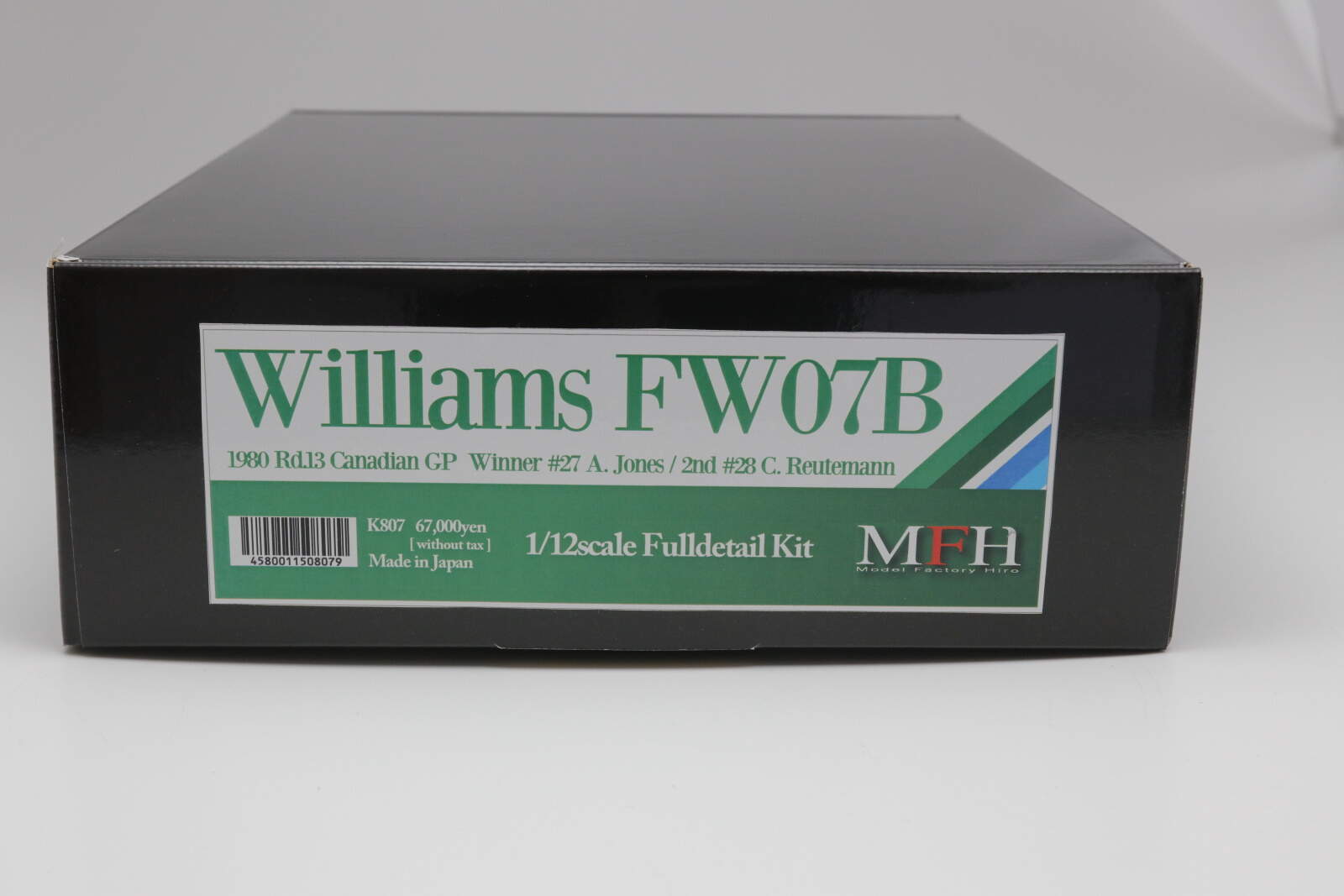
The MFH kit represents the FW07B, the car that sealed the deal for Australian Alan Jones in Montreal, Canada at the 13th, and penultimate, race of the 1980 F1 championship. Williams had already won their first F1 constructors’ championship in a dominant season. Their cars only failed to score points once and they won 7 of 14 races with 11 other podium finishes.

Interestingly, F1 has gone back to ground effects cars for the 2022 season to help level the playing field and hopefully promote close racing. They seem to be having the same problems today they did forty years ago of the ground effect being too powerful forcing the cars to bounce up and down – porpoising – at high speed.

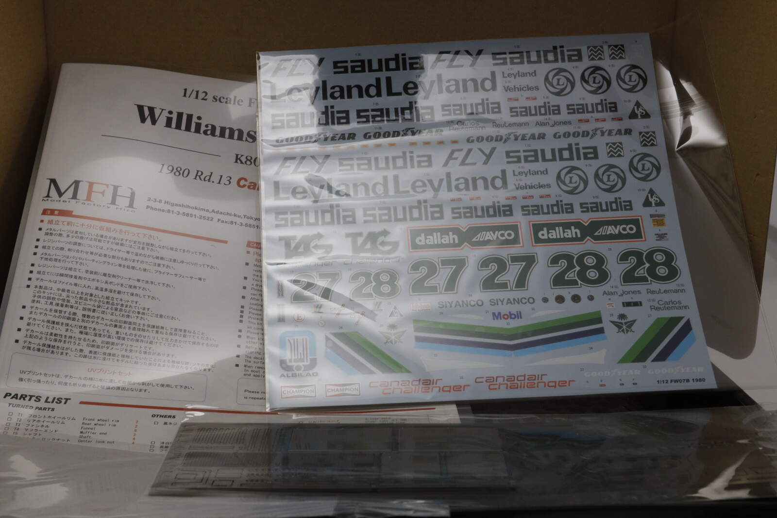
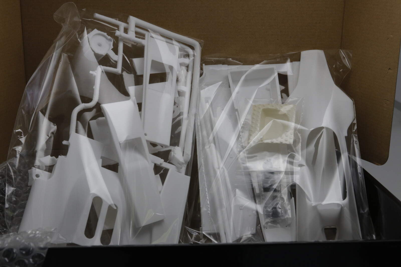
Here’s a quick view of contents:


The car was sponsored by Saudi Air, I think the first time for Middle Eastern sponsors on an F1 car.

The body is largely resin with a few metal panels which should be easier to manage.

Painted tyres and aluminium hubs

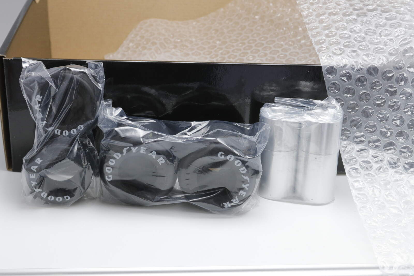
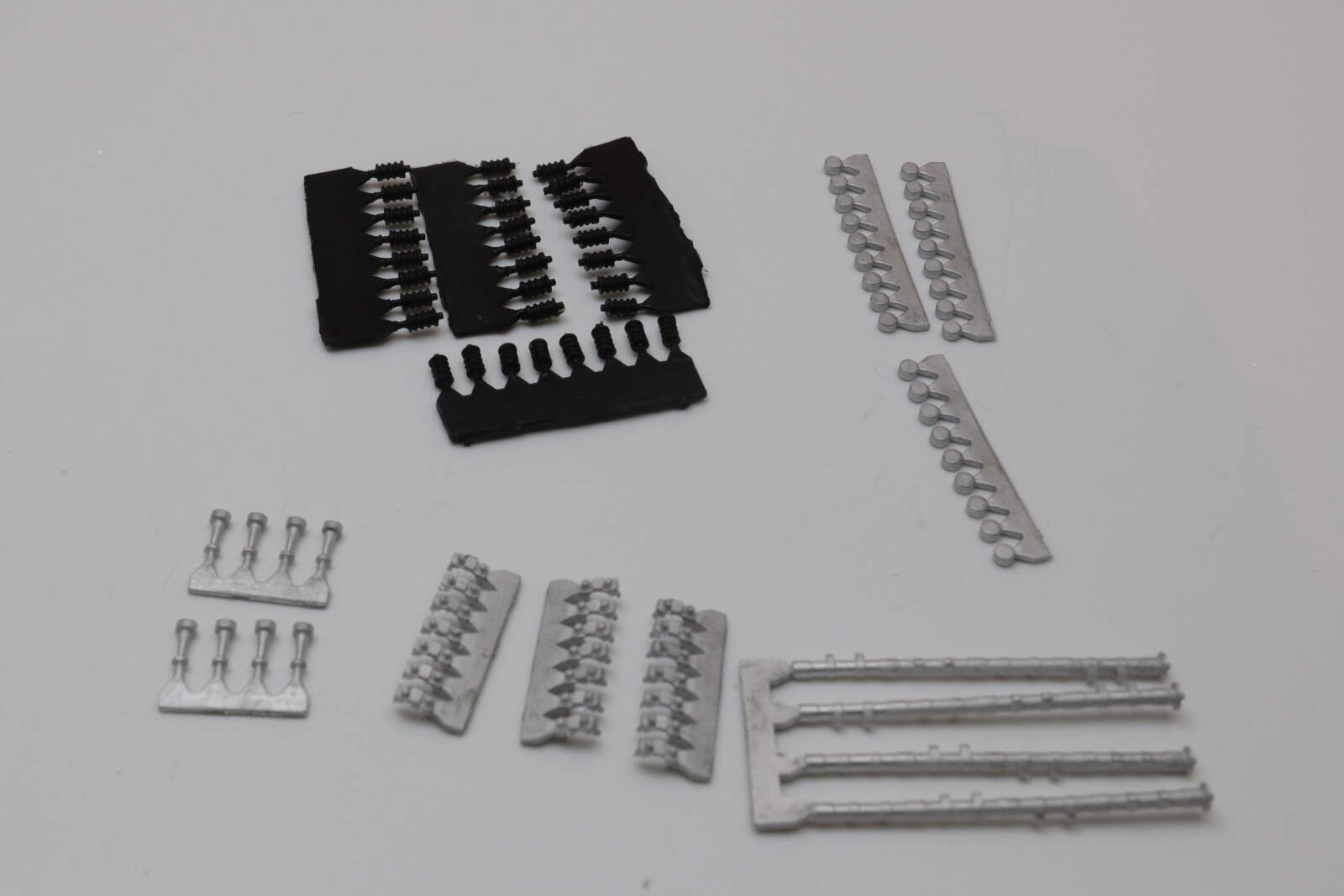
and a whole pile of white metal

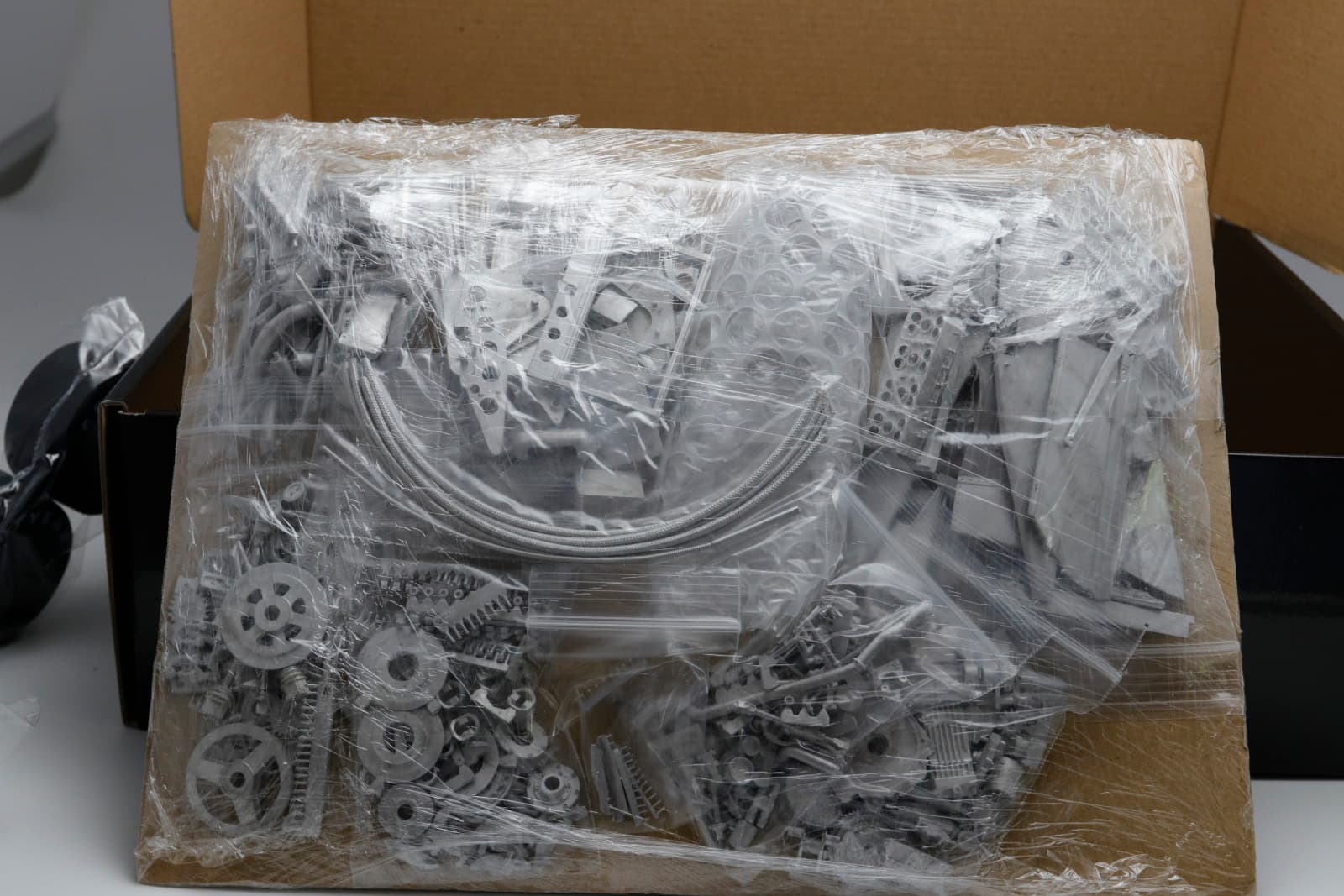
The metal parts are very good. I think this is because this is a brand new kit from MFH so I don’t know whether they have improved the moulding process or just new moulds produce this effect.

On to the build.
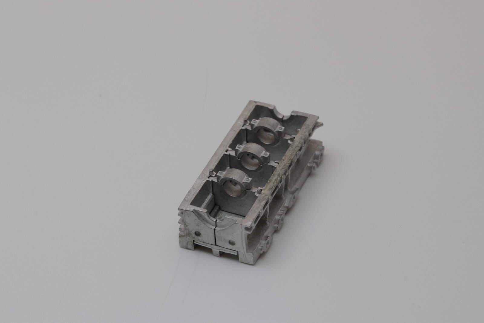
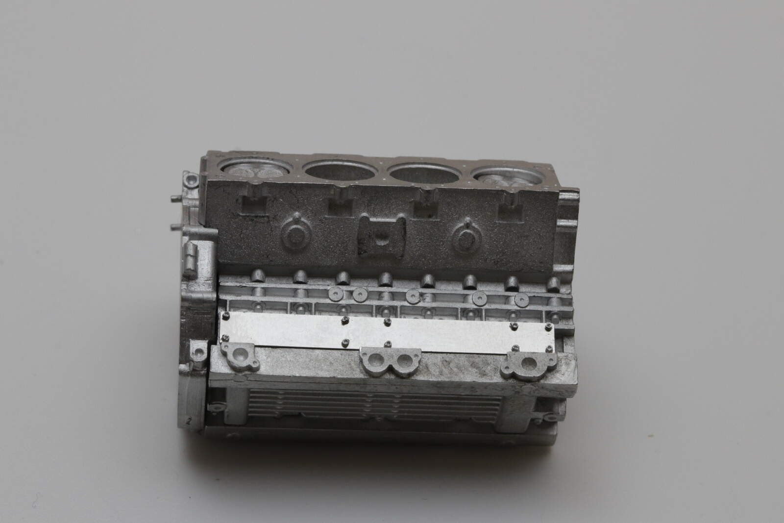
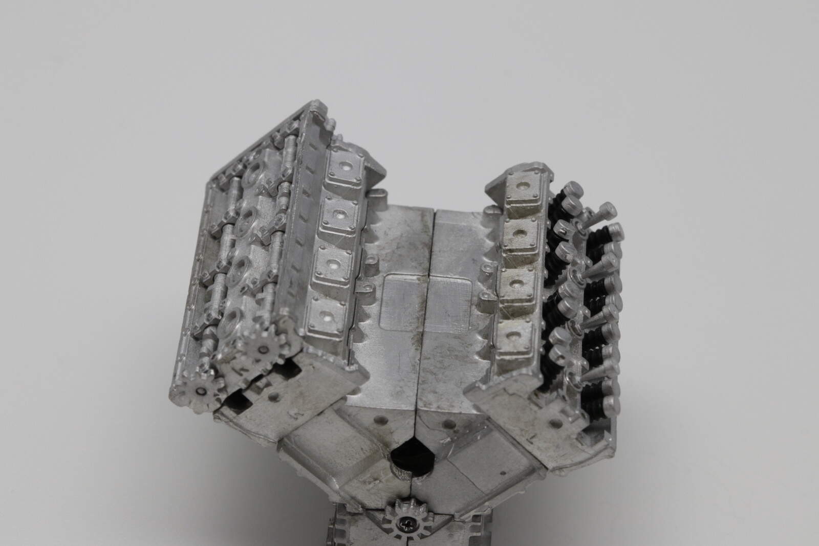
This is my fourth MFH kit so I have a good idea what to expect. As with the previous kits, we start with the engine. Now I have built a flat 12, a V12 and a V twin so my first V8.
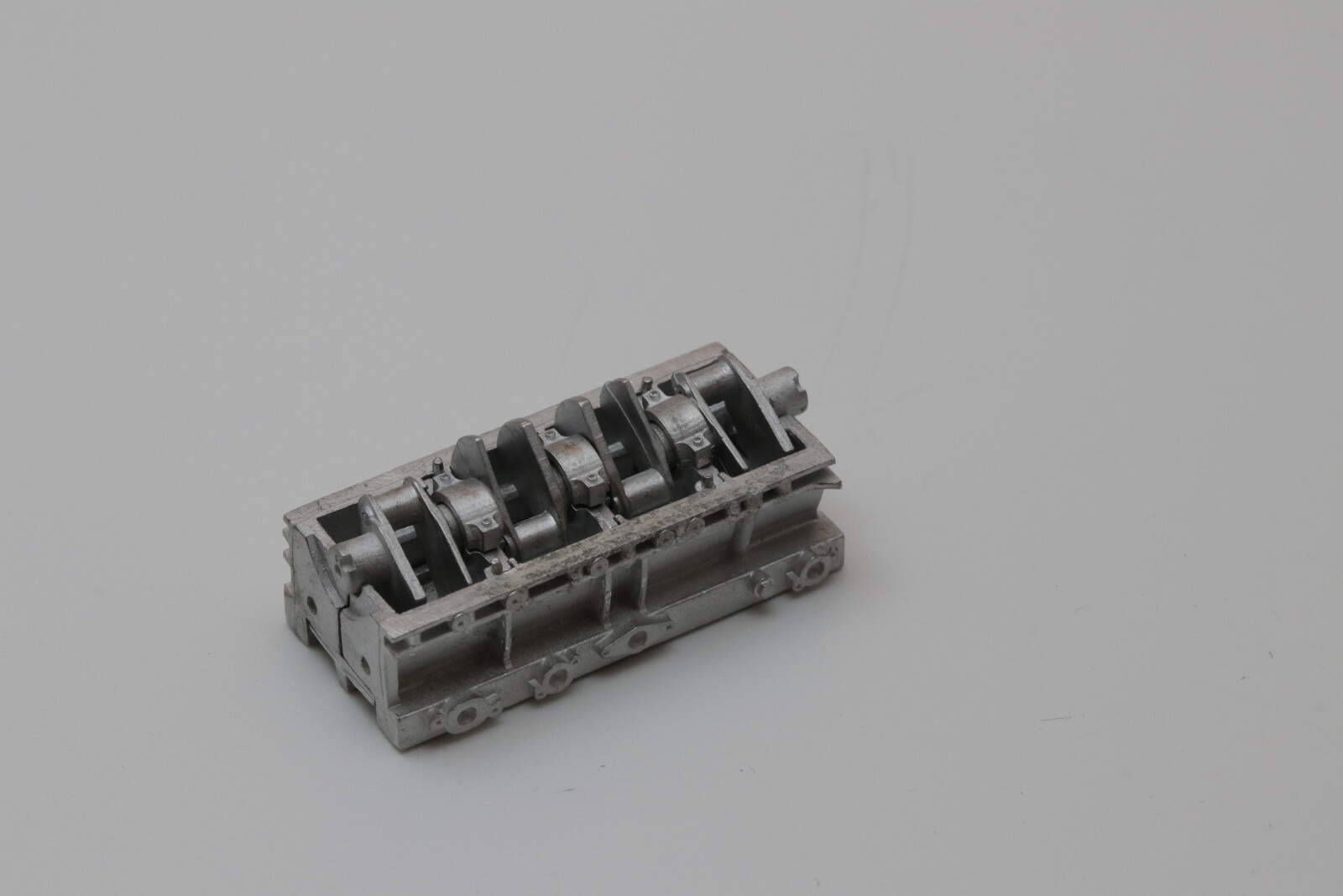
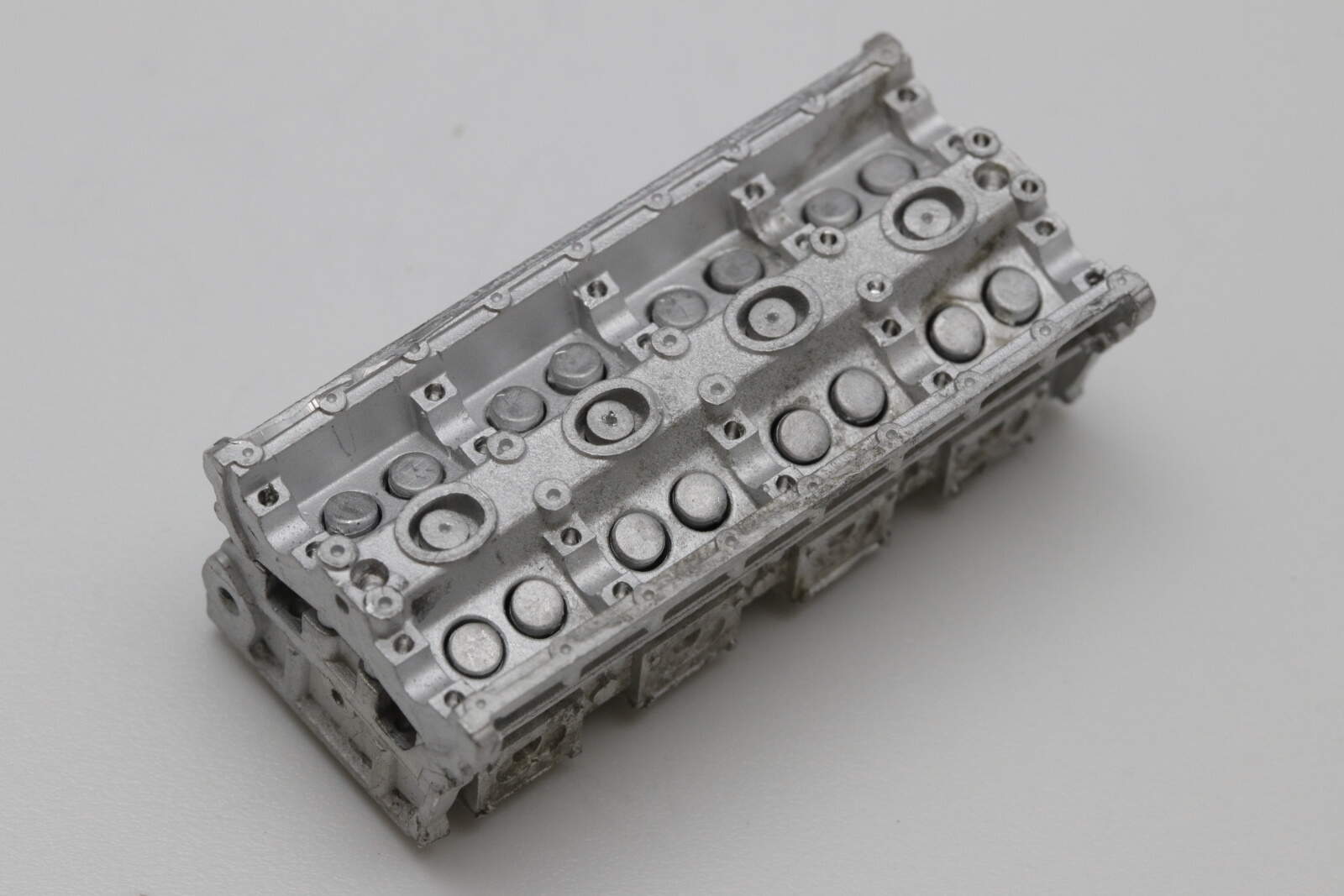
There is a twist with this V8 that I hadn’t appreciated - it comes with an interior!

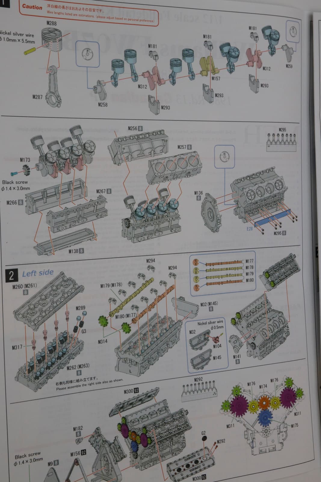
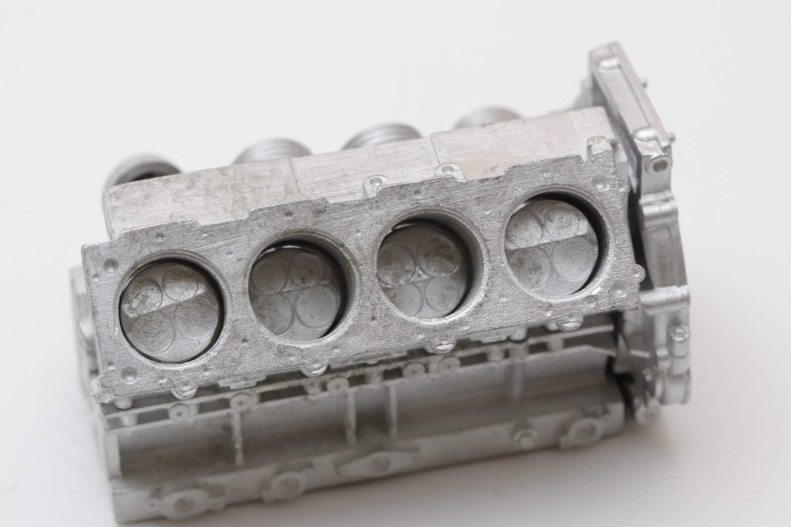
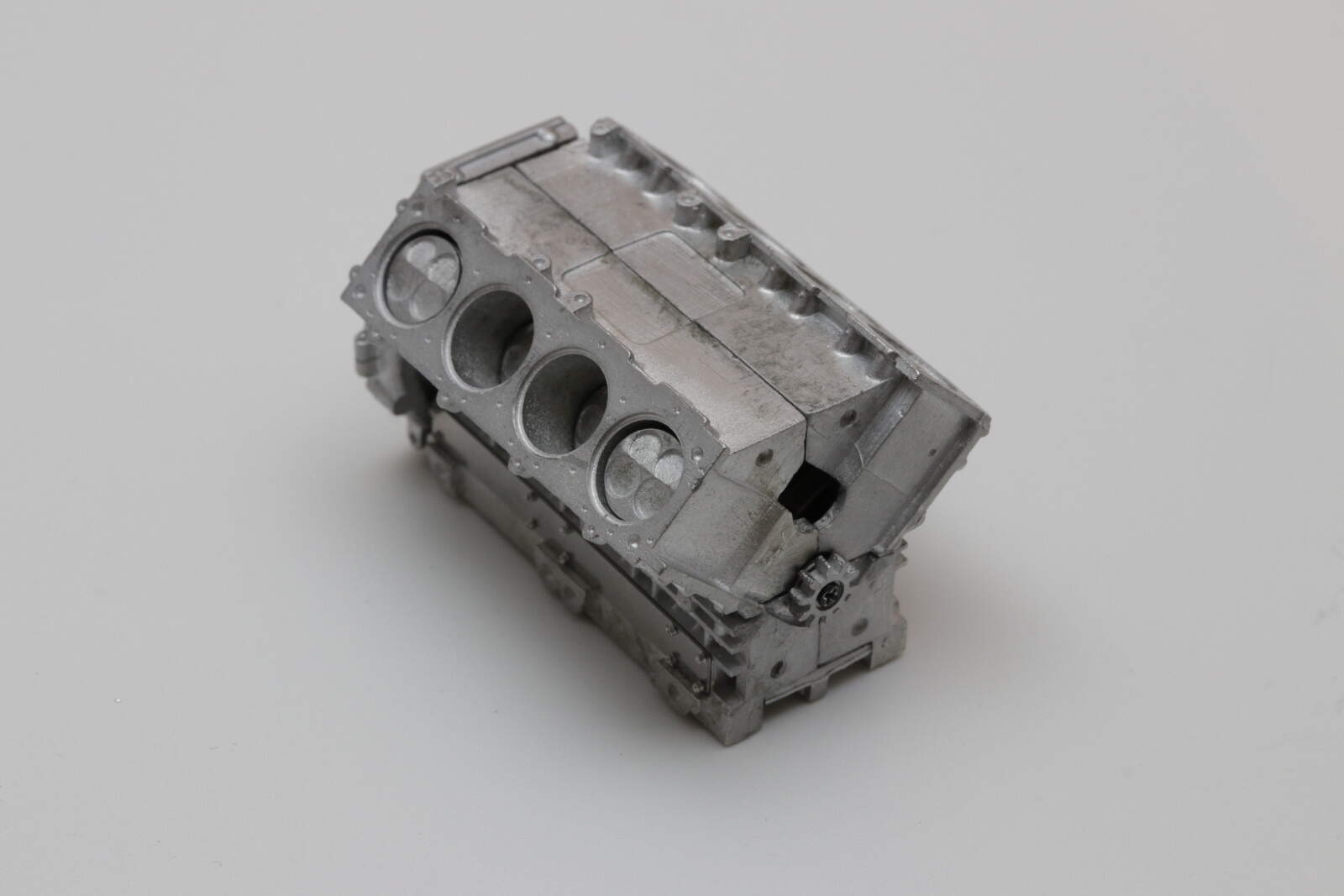
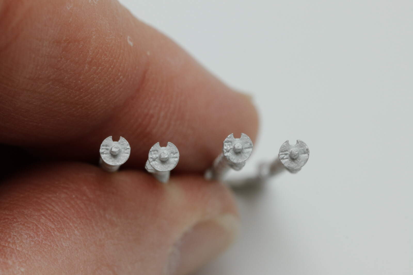
Yep, pistons, conrods, crankshaft, valve springs, camshafts, you name it. Why you ask since of course it will all be invisible when complete. The parts are very nicely cast though

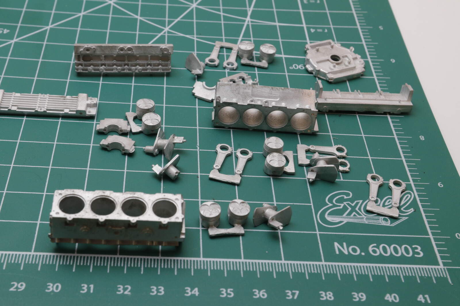
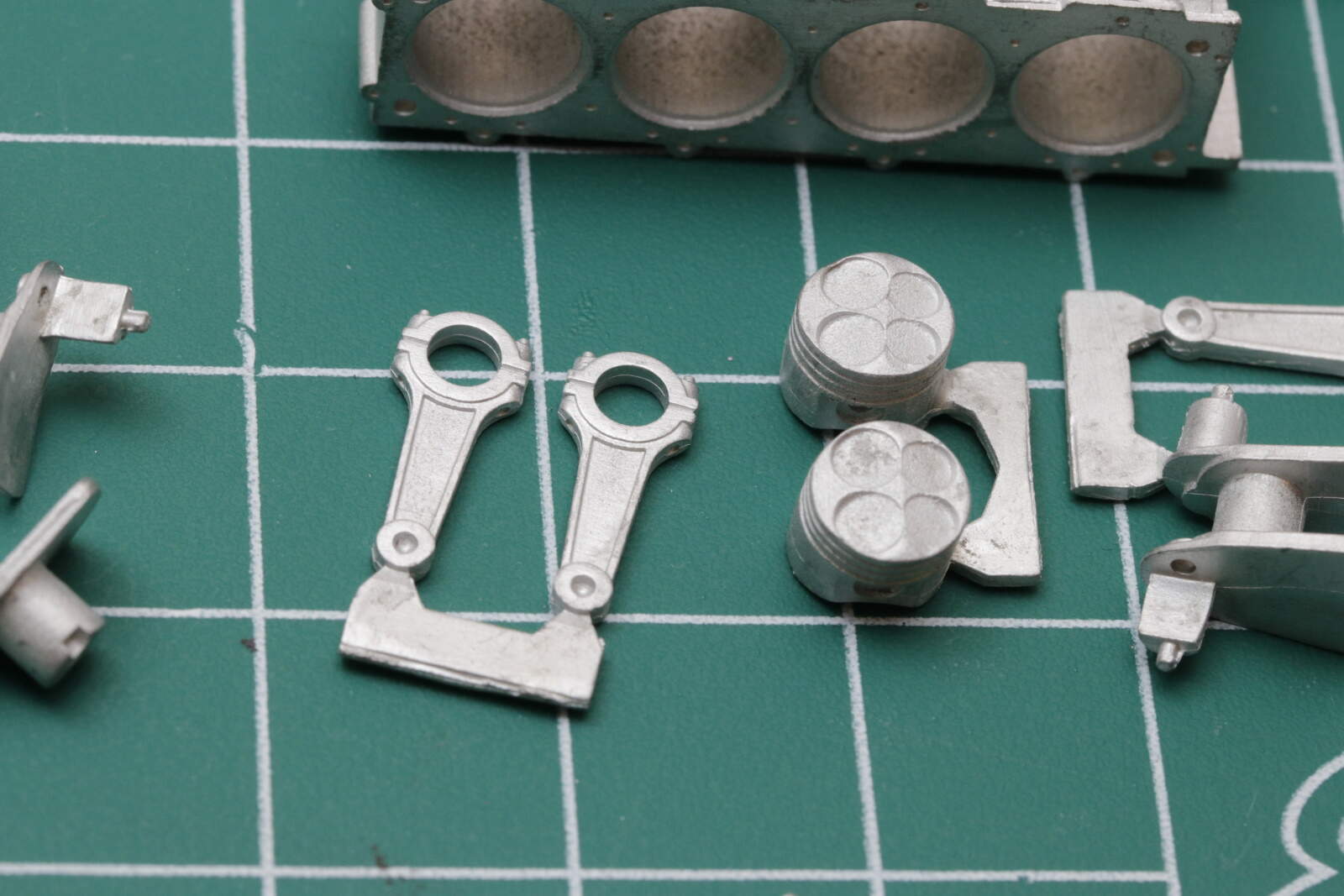
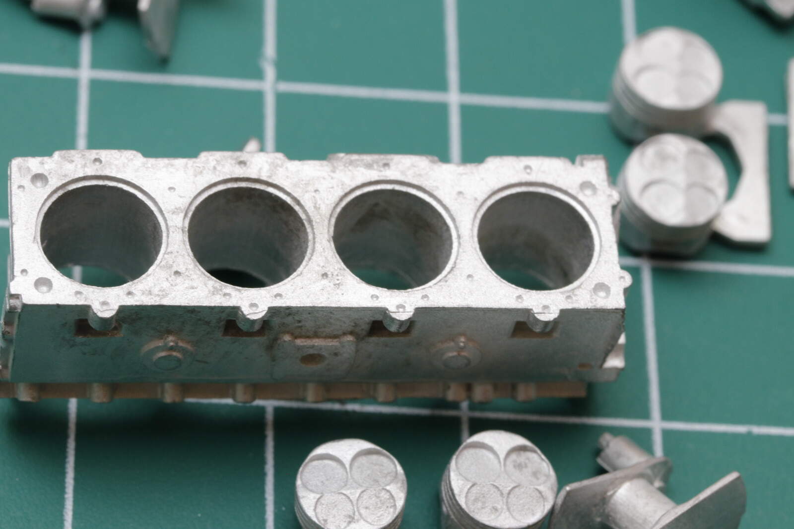
So what do you think, give it a go? or be sensible and just build the block without internals? (and aside that Richard will appreciate - there are over a 100 holes to drill for the first 2 steps!)

Let me know what you would like to see.

cheers
Michael

4 Likes

Looks incredible, bit of a shame to build it all and hide it. If only you could get the main components to build both an in car and out of car engine. Gonna watch along as you go for certain.

Keith

1 Like

If it was my kit, I would build the full engine interior. It might not be visible, but I would have fun building it and afterwards, I would know it was there.

2 Likes

I’ll be watching this one for sure Michael !
The Barchetta kit I recently purchased also has full internals but V 12 . Yours is a V 8 with 4 valves per cylinder while mine is 2 per cylinder IIRC .
It would appear that yours has real valve springs ?
Mine has castings representing the valve springs I think so I don’t see how the valves will actually work , and unlike yours which has marks on the timing gear train to assure proper valve timing, I don’t believe mine does but I will study it further.
I haven’t opened up the white metal bits yet but I am hoping they are all flawless as this is their newest kit - we’ll see.
I am tempted to say build the internals as it will be an interesting experience but then does that mean I must commit to the same ? LOL - do as I say , not as I do .
Go for it .
Cheers - Richard
Edit - I just looked over your instructions and I don’t see valves - only springs/tappets. Are there indeed valves ?

1 Like

Now this looks amazing! It will be great to see it done up as AJ’s car as well!

With regard to the full engine detail, I say rip into it! What are you going to do with the parts if you don’t assemble them? You paid the :moneybag: :moneybag: :moneybag:, get your full value.

Cheers, D

1 Like

Michael,
Now this is going to be one very special build for yours truly to follow. I will always be a huge Sir Frank Williams fan, and the FW07B is an all time favorite just being right behind the infamous FW14B of Nigel Mansell.
I’ve never seen such a detailed 1/12 engine before, and I do question MFH’s reasoning for doing one to this level of detail knowing that once built and installed, no one will ever be able to see that level of detail. They’ve even included intake and exhaust cams for both sides!! Still, being a certified gearhead, I urge you to do the full build.
I’m going to be paying super close attention, taking notes, and even clipping pics at times, as I do have sitting in my not so big F1 stash the Tamiya 1/20 scale Williams FW07B with Indy Cal decals. So I’m going to be the student and you’re my teacher and mentor. Can’t wait for the 1st update.
joel

1 Like

Well thank you all for your vote - seems the outcome was inevitable.
@kornbeef Thanks Keith, glad to have you along for the journey. I did think if you were doing a dio it would be great to have these ready made engine parts around the workshop. Certainly add some realism.
@Hwa-rang Hi Jesper, yes are right. I have enjoyed it so far (See below) as it hasn’t been as awkward as I thought it maybe and I will always know it was there.
@RDT1953 Hi Richard looking forward to your magic on the little Ferrari engine. You right about the valves, got a bit carried away, it is just the springs.
@AussieReg If there had been a price option I may have gone for the savings :grinning:
@Joel_W Great capture on the Tamiya kit. I knew they had made one but I have never seen one for sale so hopefully one day I will see it on your work bench.

So first steps - a dry run to see how it all works.
Pistons and crankshaft


Sump setup for shaft

and shaft in place - the detail is pretty cool and not a bad learning exercise for non-mechanical person like me

and last the fiddly bit, getting those pistons in the right order and into the cylinders

and from the other side - fortunately MFH overbored the cylinders so not a tight fit

cheers
Michael

4 Likes

Quite a bit of piston slap there. :smile:

Don’t forget the circlips for the wrist pins (gudgeons on your side ) and piston rings . LOL .
Maybe MFH supplied standard bore pistons and cylinders at max over … :wink:

Michael,
MFH will make a race car mechanic out of you yet.

joel

Maybe if I put in some sleeves that will help! The piston rings are sadly missing from the kit, as are the valves so we won’t be getting too much HP from this V8.

cheers
MIchael

Michael,
Not much HP and no torque, but if you do manage to get the engine to fire up, you’ll be blowing more smoke then you can imagine.

joel

Michael, a man with your skills should be able to sleeve out those cylinders in no time! :thinking: :flushed: :sunglasses:

Awesome progress, loving this!

Cheers, D

1 Like

The block is complete and not surprisingly I guess, if you rotate the cog the pistons move up and down in the cylinders. It may fire up yet!


And another reminder of MFH’s attention to detail. the blanking plate has 10 x 0.7mm bolts to hold it in place.

And onto the next layer. The head comes in two parts, one layer for the springs, the second for the camshafts. The picture shows top and bottom of each and the level of details for something that will be completely hidden, and, the piece on the left shows the missing valves :grinning:

And a question for the historians - the cover plate is stamped with Cosworth. When you look at photos of early engines - late 60’s through to late 70’s they all have Ford on them. Does anybody know why they switched? It seems for the last 3 or 4 years of the DFV it was Cosworth on the engine.
The internals - we have springs, caps for them that the camshafts push on, the camshafts, clamps for the shafts and ignition points.


Now the springs are made of rubber, that’s because when this all hooked up, and don’t laugh, the camshafts will operate with the pistons moving. And not any old camshafts, more attention to detail here, we have left and right inlet and exhaust cams

Lot more holes to drill first so I can seat everything and we will see if it purrs like a V8!

cheers
Michael

2 Likes

Good question Michael re: Cosworth on the cam covers.
I was unaware that the Ford logo was replaced at some point . I know that Ford paid Mike Costin and Kieth Duckworth $ 100k to develop the engine and they initially built an inline four - essentially one half of the V8 - to test their concepts. Perhaps Ford’s interests in the engine were only protected for a number of years . I also understand that the engine was largely the creation of Duckworth and was his first . Quite a success I would say - the longest reigning F1 engine ever and I believe it was used in other venues as well . Joel can probably answer these questions better than I.
Nice job on the engine - glad you opted to do the internals and of course I now have no choice but to do the same … LOL
Cheers - Richard

Michael,
Absolutely a great job in building the 3.0L Cosworth engine. can’t wait to see and hear it running on one of Richard’s miniature Dynos :rofl:

Honestly, I never really paid much attention to which name was on the cam covers of F1 engines back then. It was my understanding the Cosworth was on the F1 engines, while Ford’s name was on the American Cart engines that were designed and built by Cosworth for Lotus.

These engines weren’t 3.0 Liters but 2.65L turbo charged engines that Lotus 1st brought to the Brickyard and were named DFX Ford’s as once again Ford footed the entire bill.

If you thought that the F1 Cosworth’s were king of the hill, the Cart engine won the Indy 500 10 years in a row, and was the dominant engine during it’s life span with more then 150 Victories.

I’d have to do some research to see if and when the Ford name did appear on F1 engines.
joel

Micheal
Just catching up and will be following with great enthusiasm and interest. The detail of MFH kits I find simply
amazing and normally I avoid spending time adding details that will never be seen but on these kits, that detail is part of the charm and the experience and completely agree, needs to be done. Engine work looks superb and at times, I nearly fall off my chair.
Peter

Thanks joining in Peter. Certainly MFH has it own approach to detailing, sometimes extreme and other times I wish they had done a little more but they’re there to challenge you to do what you want and make it what you want.

cheers
Michael

Looks like I need a bit research on the Ford Cosworth question.
Any way the engine build moves along.
Got the springs in


You can see them all tucked in for the camshafts

and then the camshafts themselves

If you wanted to do a workshop dio showing maintenance on a DFV this would be a good starting point.

cheers
Michael

2 Likes

Michael,
The level of detail that MFH has painstakingly created within the DFV engine is simply beyond anything I’ve ever seen or imagined. And your skills to assembly it to these standards are equally amazing.
I’ve also been puzzled to the answer to your question about when did the Ford Cosworth DFV engine drop the Ford name on the came shaft covers and replaced them with Cosworth. As I previously said, that’s something that I never really paid much attention to, so I decided to see if I could figure it out by looking at pictures of Lotus and other Cosworth powered cars from 1967 onwards. All Lotuses F1 cars were Ford Cosworth powered till 1987 when they switched to Honda power. I was able to verify almost every year with photos of cars with their engines. But once the car manufactures started using engine/trans covers it got a lot harder. So I still don’t have a definitive answer to this nagging question that’s keeping me up at night.
joel